Bicycle drivetrain
From DDL Wiki
Contents |
Executive Summary
To optimize the design of a chain tensioning device (be it powered by human power or an external source), the first step was to dissect the use of an existing application. A single, fixed-gear bicycle was acquired and dissected; areas of improvement were addressed via DFMA, FMEA and DFE.
Results from the product usage and evaluation study had proven that the system was not only incredibly non-intuitive, but required far too many specific tools to work on in an emergency situation. Though the subject was technically inclined, results from an attempt to tighten the chain were incredibly poor and could easily result in injury. Even when this task was completed successfully, the tire was crooked, another opportunity for injury.
Our study of DFMA revealed the drive train system, while well made, was not designed with final assembly in mind. The manufacturing processes result in a durable, aesthetic product. However, there is still room to reduce production costs by a fair margin. Through minimization of part count as well as component and feature simplification it should be possible to reduce the production cost. Design for assembly leaves much to be desired. The design results in a system which requires specific installation orders and often obstructed access. The process is time consuming and requires a fair amount of training or experience to complete. Some of these shortcomings may be due to the fact that often the customer ultimately assembles the components.
FMEA results showed that most of the higher RPN failure modes were related to issues with lack of and improper maintenance on the drive assemblies. Specifically, improper lubrication and tension on the chain can cause slip/loss of drive likely resulting in harm to the user. These results suggest that a design solution that makes this maintenance easier or not required would greatly reduce the likelihood and severity of failures.
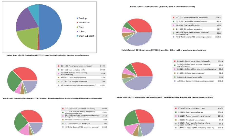
From the DFE analysis, we found that the amount of greenhouse gas emissions released in the manufacture and use of the product is fairly low. The largest contributor is bearing manufacture, but even if a $30/mtCO2eq tax went into effect, the total cost increase would be less than 2%. Considering how the product is used, it might be more environmentally friendly to make improvements that increase its appeal to consumers, instead of focusing on improving manufacturing processes. Having more people willing and able to use bikes could drastically reduce GHG emissions by reducing the use of cars, even if the GHGs released during manufacture do not change significantly.
Thus, the existing product was found to have quite a few issues. It is the goal of this team to improve the existing design as well as possible within the budgetary restrictions. Subsequent analysis will investigate these points further and determine possible design solutions.
Primary Stakeholders and Product Needs
The primary stakeholders in this supply chain are the Manufacturers, the bike shops who will retail this and the bike riding consumer.
Consumers:
Consumers are the target audience who purchases the product, these people would most likely own one or more single speed road bikes and may or may not be hipsters (but probably)
- Ease of use for both alignment and tensioning of the rear wheel
- Robust construction for reliable road use
- Low weight because this is a human powered vehicle
- Lowest possible cost for a quality product
- Ease of maintenance
- Compatible with many bike frame designs, IE not a custom part for each frame
- Easily installed on bikes not currently using it
- Weather resistance
Retailers:
These are the people and companies that would sell the product to the consumers
Most likely this would be from specialized bike shops (IE iron city bikes)
- Small size for easy storage
- Universal compatibility use so they do not have to stock more than a couple sized/configurations
- Ease of maintenance
- Low price
Manufacturers:
Manufacturers create the product for sale and effects on time and pricing impact the entire supply chain.
- Time to manufacture is important and all custom machined parts slow down the process
- Cost to manufacture and of materials; exotic materials would not be good here.
Product Function and Evaluation
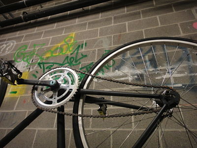
This application of a single-gear bicycle drivetrain offers a cost-efficient solution for transportation. It forgoes torque/power control for simplicity and low cost. The chain tensioning system is of particular interest as it is rudimentary and difficult to perfect.
Usage
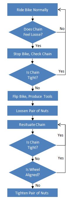
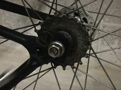
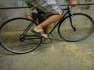
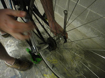
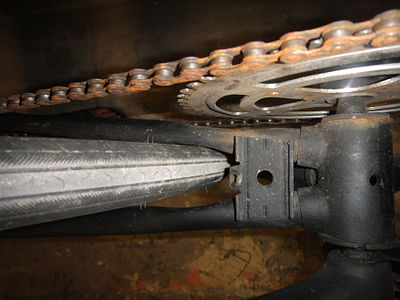
If a user is riding a bike and senses that it can be loose, he or she should stop and check the chain visually. If it feels loose, flip the bike, and hope you carry two 15mm socket wrenches. Loosen the pair of nuts holding the rear hub assembly to the chassis and visually tighten the chain. Hoping that the tire is now in line with the bike, tighten the two nuts back into place and put your tools back in your pocket.
Mechanical Function
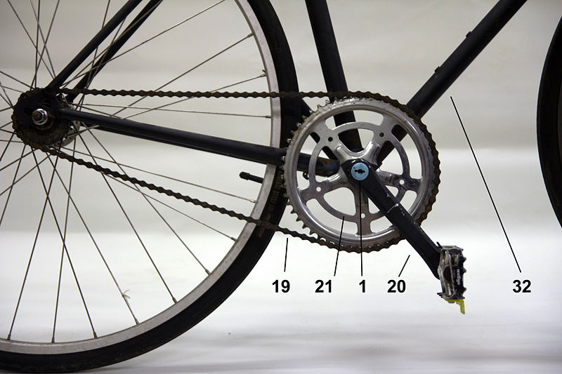
The pedal is pushed upon by the user's foot, which in turn imparts a moment on the drive sprocket via the crank lever arm. This moment is shared to the rear sprocket through the chain, which in turn imparts a moment to the rear wheel through the rear hub. The chain tensioner is a simple friction-compression nut solution that holds the tension in the chain by the friction against the threads.
Preliminary User Study: Chain Tensioner
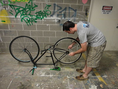
The preliminary use study allowed for some very obvious conclusions, most of which were negative. The subject was quite technically inclined, but ended up with a system more unsafe than what he started with. This is largely due to the fact that the slop in the system allows for some tragic results that can climax in a serious injury to the user.
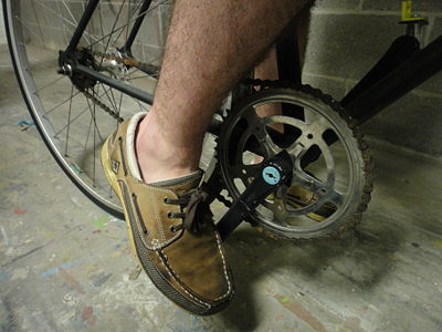
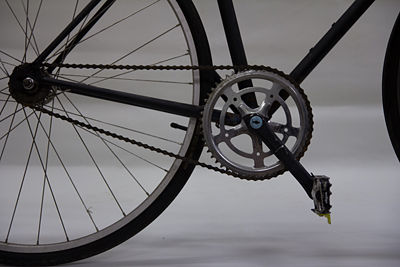
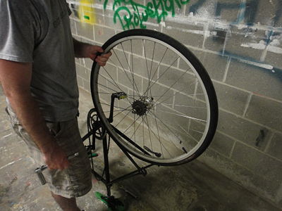
The user was asked to assume that the chain was not tensioned enough. From the usage flow chart, we see that the first step was to flip the bike upside-down and produce tools. We had to provide the tools as they were esoteric and not readily available. The user then loosened the rear hub (though it should be noted it took some trial and error to figure out what to act on), and proceeded to tighten the chain. Without knowing how tight to make the chain, the user went with what he thought was good enough, but from the pictures below, it was obviously incorrect. The user also did not align the wheel with the chassis, which could end in catastrophe under load.
Thus, there's a lot of room to improve the system. This usage study was a very important tool for future decision choices.
List of Parts
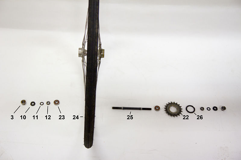
The following details the list of parts of a fixed gear bicycle tensioner and drivetrain.
Parts list table
| Part Number | Name | Quantity | Mass (g) | Subassembly | Function | Material | Manufacturing Process/ Purchased Component | Image |
|---|---|---|---|---|---|---|---|---|
| 1 | Dustcaps | 2 | <1 | Crank Assembly | Keep dirt out of bottom bracket | Plastic | Injection Molding | |
| 2 | Lock nuts | 2 | 6 | Crank Assembly | Retainment/Assembly | Steel | Catalog Purchase | |
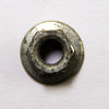
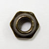
| 3 | Nut w/ integrated lock washer | 2 | 16 | Crank Assembly | Retainment/Assembly | Steel | Catalog Purchase | |
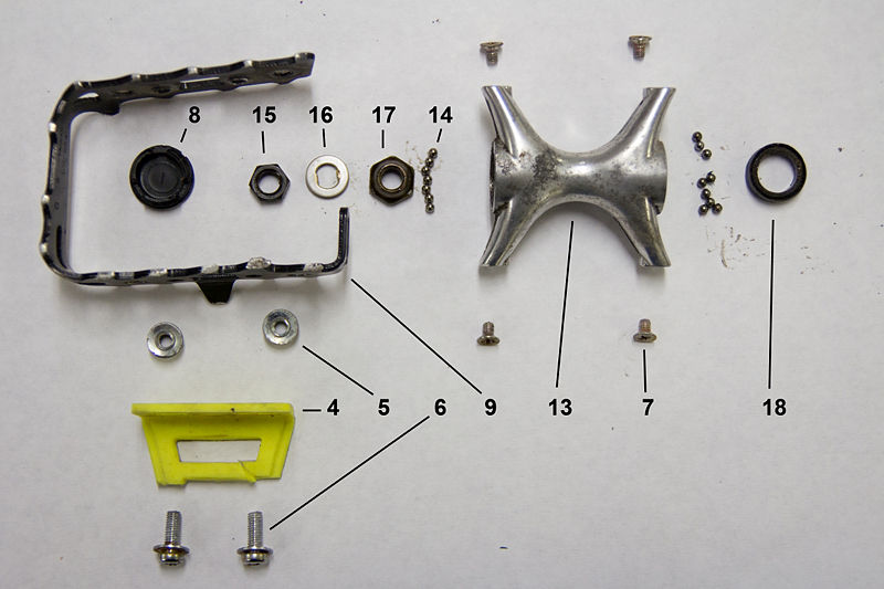
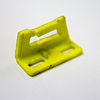
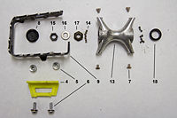
| 4 | Toe strap holders | 2 | 6 | Pedals | Ability to secure toe | Plastic | Injection Molding | |
| 5 | Flange nut | 4 | <1 | Pedals | Attach toe strap holder to foot grip | Steel | Catalog Purchase | |
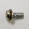
| 6 | Screw w/ integrated washer | 4 | <1 | Pedals | Attach toe strap holder to foot grip | Steel | Catalog Purchase | |
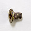
| 7 | Screw | 8 | <1 | Pedals | Attach foot grip to pedal | Steel | Catalog Purchase | |
| 8 | Pedal cap | 2 | <1 | Pedals | Keep dirt out of pedals | Plastic | Injection Molding | |
| 9 | Foot grip | 2 | 27 | Pedals | Prevent foot from slipping off pedal | Aluminum | Die Casting | |
| 10 | Outer jam nut | 2 | 9 | Sprocket Assembly | Retainment/Assembly | Steel | Catalog Purchase | |
| 11 | Washer | 2 | <1 | Sprocket Assembly | Retainment/Assembly | Steel | Catalog Purchase | |
| 12 | Inner jam nut | 2 | 7 | Sprocket Assembly | Retainment/Assembly | Steel | Catalog Purchase | |
| 13 | Pedal | 2 | 54 | Pedals | Central Component in Pedals | Aluminum | Die Casting | |
| 14 | Ball bearings | 24 | <1 | Pedals | Friction Prevention | Steel | Catalog Purchase | |
| 15 | Nut | 2 | 3 | Pedals | Retainment/Assembly | Steel | Catalog Purchase | |
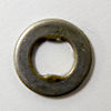
| 16 | Double D Washer | 2 | <1 | Pedals | Catalog Purchase | Steel | Catalog Purchase | |
| 17 | Nut w/ seat for ball bearings | 2 | 5 | Pedals | Retainment/Assembly | Steel | Catalog Purchase | |
| 18 | O-ring | 2 | <1 | Pedals | Keeping lubricants inside pedal | Rubber | Catalog Purchase | |
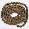
| 19 | Chain | 1 | 304 | Drivetrain | Drive rear sprocket using rotation of front sprocket | Steel | Stamping and Pressing | |
| 20 | Crank | 1 | 260 | Spindle/Crank Assembly | Lever arm for force from foot | Steel, aluminum | Die Casting | |
| 21 | Crank w/ sprocket | 1 | 626 | Spindle/Crank Assembly | Transfers force to chain | Steel | Assembly - Stamping and Die Casting | |
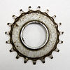
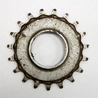
| 22 | Rear sprocket | 1 | 82 | Rear Hub Assembly | Sees force from chain and sends it to the tire | Steel | Stamping with Post Machining | |
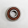
| 23 | Bearing | 2 | 19 | Rear Hub Assembly | Reduces system friction | Steel, Aluminum | Catalog Purchase | |
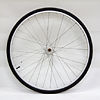
| 24 | Rear wheel | 1 | ? | Rear Hub Assembly | Interface between rear sprocket and ground | Steel, Rubber, Aluminum | Assembly - Catalog Components Mated with a CNC lathed hub | |
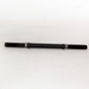
| 25 | Rear axle | 1 | 101 | Rear Hub Assembly | Allows wheel to move | Steel | CNC Lathing | |
| 26 | Sprocket retaining ring | 1 | 15 | Rear Hub Assembly | Holds sprocket components together | Steel | Catalog Purchase | |
| 27 | Ball bearings | 2 | 14 | Spindle/Crank Assembly | Countering Friction in Pedals | Steel | Catalog Purchase | |
| 28 | Left threaded cap | 1 | 54 | Spindle/Crank Assembly | Retainment/Assembly | Steel | Catalog Purchase | |
| 29 | Spindle | 1 | 209 | Spindle/Crank Assembly | Allow wheel to move | Steel | CNC Lathing | |
| 30 | Right threaded cap | 1 | 47 | Spindle/Crank Assembly | Retainment/Assembly | Steel | Catalog Purchase | |
| 31 | Crank Spacer | 1 | 47 | Spindle/Crank Assembly | Retainment/Assembly | Steel | Stamping | |
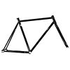
| 32 | Frame | 1 | 2272 | Frame | Holds all other subassemblies | Steel | Fabricated/Welded |
Design For Manufacturing and Assembly [DFMA]
Design For Manufacturing [DFM]
Dissection of the fixed gear drive train revealed several areas for improvement. The majority of the drive train consists of cast or stamped steel and aluminum components which allows for a high volume of relatively cheap parts to be made. High tolerance components such as the rear axle, hub and spindle are likely CNC lathed in order to achieve required tolerances for bearing surfaces. Unfortunately this drastically increases the time and money spent to produce such parts. However, considering the cost of machining the rear hub it is multifunctional: it locates the bearings, provides torque transfer and mounting for the sprocket and secures the wheel. It should be noted some components of the pedal assembly (dust cap, toe strap holders) are injection molded plastic, allowing for very cheap manufacture after initial mold investment. Interestingly, it seems the use of injection molded plastic for other applications such as the pedal and pedal grip could be a viable option at the expense of some durability. Furthermore, standardizing bearings between the pedal set, crank assembly and hub could reduce costs and increase the feasibility of injection molding the pedal set. Other notable components include the rear hub, sprocket and retaining ring and their method of interface. The hub uses a stepped threaded area in order to accommodate the larger diameter sprocket and smaller diameter retaining ring. This setup increases manufacture time and cost by requiring two separate sized threads to be machined onto the hub as well as a lip machined into the sprocket for the retaining ring to seat against. Instead a single diameter thread may be used along with a locking nut. A similar oversight occurs in the pedals where ball bearings are retained by a special nut and jam nut instead of a single bearing set and lock nut assembly.
Overall the materials and production methods provide a durable, well finished system but certainly leave room for improvement. By minimizing part count, standardizing components and design features and simplifying parts it should be possible to reduce the production cost by a fair margin.
DFM Summary
- The drive train is made of durable, aesthetic pieces at the expense of production cost.
- Casting and stamped processes are used where applicable to reduce high-volume cost.
- The drive train uses many non-standardized parts across the system.
- Some components are excessively complicated or superfluous for their function
Design for Assembly [DFA]
Dissection of the fixed gear drive train show inconveniences that negatively affect assembly time, assembly worker training and labor cost. It is likely several of these inconveniences are a result of the fact that assembly is completed by the customer as well as standard bike specific tooling. An experienced user is required to install the drive train assembly correctly as there are many components with no clear assembly order, especially in the bearings for the pedals. Additionally parts must be installed from several directions and access is often obstructed if the system is assembled in the incorrect order. For example, there is no feature in the pedal grip to allow for pedal removal. Instead, it is necessary to remove the pedal grip to gain access to the nut for pedal removal. This may be easily remedied through a clearance hole in the pedal grip. Additionally, the use of unnecessarily thin retaining rings and sprocket requires 2 special bike wrenches which are significantly thinner than standard wrenches. While this is relatively standard in the biking industry for enthusiasts or shops, it certainly inconveniences an average user looking to conduct maintenance or repair. Also, special care is required when installing the pedal bearing set as it is made up of many individual parts and requires specific assembly order. Tens of ball bearings must be installed, followed by a custom nut requiring specific orientation, a washer and lastly a jam nut. This is a mistake prone assembly and also requires quite some time to install due to the many separate components. There are, however, some well thought out components which ease assembly. For example, the pedal grip uses slots for mounting which maximizes installation compliance, even in the event of a warped or damaged grip assembly. Also, integrated washer/nuts are used to hold the wheel to the frame, minimizing the number of fasteners on a part which is likely removed often.
While there are some positive points for the drive train assembly there are still numerous ways to improve upon installation simplicity and time. We believe there may have been a lesser focus on design for assembly due to the fact that these components are often assembled by the customer. As such the manufacturing company realizes no lost revenue (other than customer backlash) due to the relatively inefficient design.
DFA Summary
- The designers likely did not prioritize installation simplicity or speed.
- Special tools are required for proper assembly.
- The installation process is mistake prone and requires a fair amount of experience.
Failure Mode and Effect Analysis [FMEA]
Failure Mode and Effect Analysis was performed on the drivetrain of the fixed gear bicycle. This was used to identify the cause, effect and ease of detection of mechanical failure in the system. This is done by scoring major components in factors of (S)everity, (O)currence and (D)etectibility. These scores are multiplied to determine a Risk Priority Number, which allows us to best identify areas that need improvement.
| Item and Function | Failure Mode | Effects of Failure | S | Causes of Failure | O | Design Controls | D | RPN | Recommended Actions |
|---|---|---|---|---|---|---|---|---|---|
| Toe Strap Clip: attachement for foot straps | Fracture (snapped) | Foot slips out/ distraction | 2 | Material not strong enoguh | 7 | Shorter than ground clearance to pedal | 3 | 42 | Stronger Material or method of keeping pedal upright |
| Crank bearing set: allow for pedal rotation | Dirty/ siezed | Pedals rotation feels rough or is too hard for user | 3 | Contamination from dust/dirt, lack of lubrication, not properly preloaded | 2 | dust caps | 4 | 24 | Use better sealed bearing set |
| Pedal bearing set | Dirty/ siezed | Pedal refuses to rotate independantly from crank arms/ bearings feel rough | 3 | Contamination from dust/dirt, lack of lubrication, not properly preloaded | 2 | End caps for pedal housing | 4 | 24 | Sealed end caps |
| Foot grips: provide level and tractive surface to push | Abraision, yeilding | Pedal deforms | 1 | Impact with ground during operation | 1 | N/A | 1 | 1 | N/A |
| Crank arm: transfer pedal rotation to crank/ add mechanical advantage | Fracture (casting failure) | Make bike unstable / rapid user weight transfer | 8 | Unexpected loading | 1 | N/A | 8 | 64 | Inspect at the factory |
| Chain | Oxidation / Fracture | Cause chain to skip/ rapid user weight transfer / unsatisfactory appearance | 8 | Damage to chain, rust, lack of lubrication, incorrect tension | 8 | N/A | 4 | 256 | Clear instructions on proper maintenance and easier chain tensioning |
| Rear hub bearing set | Dirty/ siezed | Wheel rotates with resistance/ seizes / bearings feel rough | 3 | Contamination from dust/dirt, lack of lubrication, not properly preloaded | 2 | N/A | 4 | 24 | Better sealed beaings |
| Rear axle | Loosening / yielding | Wheel wobbles / detaches from bike | 7 | Lack of proper tension/torque on retaining lock nuts | 3 | N/A | 6 | 126 | Make system more solidly mounted / seperate tensioning from wheel fixture |
| Rear hub | Fracture | Wheel fails | 8 | Manufacturing defects / unexpected loading (potholes) | 1 | N/A | 9 | 72 | Make system more solidly mounted / seperate tensioning from wheel fixture |
| Rear sprocket | Wear / fatigue | Teeth wear and allow chain slip | 6 | Wear from excessive use / lack of lubrication / lack of proper tension | 4 | N/A | 3 | 72 | Strengthen sprocket material / clear instructions on proper maintenance and easier chain tensioning |
The FMEA results point to the chain as the largest source of failure. Failure for this system is sudden and possibly harmful to the user if they suddenly lose balance because the pedal no longer is connected to the drivetrain. The chain skip/failure would make the bike lose functionality until normal chain positioning is restored. Also of note, most of the high RPN failure modes stem from a lack of proper maintenance and tension in the chain/sprocket/hub assembly. It seems then that a process which makes maintenance easier and a lack of proper maintenance more noticeable would lower the overall risk of failure in the entire drivetrain.
Design for Environment [DFE]
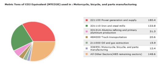
Designing for the environment involves considering the environmental impacts of manufacturing, use, and disposal of the product. In this case, the manufacturing process appears to be the most harmful, but the use phase also generates some greenhouse gas emissions (GHGs), mostly because of the need to replace tires and tubes. Using the EIO-LCA model, the amount of GHGs produced is small enough that the cost would not increase dramatically if a $30/mtCO2eq tax went into effect.
We used the known quantities of bearings and aluminum, and assumed that the drivetrain would have an expected lifetime of 10 years. We estimated that the average user would require a new rear tire every 2.5 years and a new tube every 1.5 years. The alternative calculation uses the Bicycle Parts sector, and assumes that all purchases (drivetrain and maintenance) are included in that sector. It has a result similar to adding components separately, and both calculations show that an added tax would not significantly increase the cost of the drivetrain.
Despite the relatively small amount of GHGs released, there are no clear signs that the product was designed with the environment in mind. It uses materials that can be recycled (aluminum, steel), but the coatings used to prevent corrosion are difficult to remove, and recycling is impossible with the coatings in place. Crucial components like sprockets and cranks seem durable, which could mean that it will not require the parts to be replaced. Unfortunately, if another part of the system breaks, it is likely that the entire bike would end up in a landfill. Using safe, removable coatings and making it clear which parts can be recycled would make the disposal process less harmful to the environment. Easy maintenance will increase the product's life and make it more appealing to consumers.
As shown in the EIO-LCA results, the main contributor to GHGs is bearing manufacturing. While there's no easy way to avoid using bearings in the assembly, it might be possible to buy bearings from manufacturers that use lean manufacturing processes, or that get energy from renewable sources. After bearings, tubes and tires are the largest contributor to GHGs. It is possible to reduce the number of tubes and tires used by improving quality and by ensuring that consumers know how to prevent damage, like keeping tires properly inflated and avoiding potholes.
Since the cost increase due to the possible $30/mtCO2eq tax is only a few dollars, and less than 2% of the pre-tax cost, it is possible that the tax would actually increase sales. Cars would be much more expensive to drive, so people would be encouraged to ride bikes instead. Wear and tear would increase with increased use, but replacing a few more tires would still cost less than other forms of transportation.
Team Members [TM]
Michael Ornstein - Team Leader
Rob Wojno - Product Function, Evaluation and Usage Study
Anne Dirkes - DFE
Brian Langone - DFMA
Adam Brecher - FMEA
Each member of the team expressed interest in their assigned field; work is done on a regular basis with Mr. Ornstein overlooking the direction and making sure it's in line with expectations.
References [REF]
Bureau of Labor Statistics. Inflation Calculator [Internet], Available from:<http://http://www.bls.gov/data/inflation_calculator.htm> Accessed 23 September, 2012.
Carnegie Mellon University Green Design Institute. (2008) Economic Input-Output Life Cycle Assessment (EIO-LCA), US 1997 Industry Benchmark model [Internet], Available from:<http://www.eiolca.net> Accessed 23 September, 2012.
Dieter, George E., and Linda C. Schmidt. Engineering Design. 4th Edition. New York, NY: McGraw-Hill, 2009. 707-715. Print.
