Door latch
From DDL Wiki
Contents |
Executive Summary
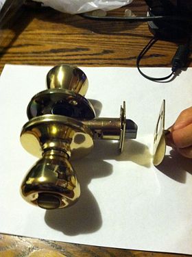
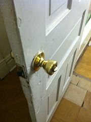
Doorknobs are ubiquitous to households; most doors have doorknobs to allow people to either open or close them as a way to offer a level of security and privacy. In an effort to brainstorm improvements to doorknobs, a common household doorknob was purchased from a hardware store and studied.
For the example doorknob, a use study showed that the product has two main functions: (1) turning the knob retracts a latch that unhinges a door from its closed position, and (2) activating the lock prevents the knob from turning. It is important to note that activating the lock does not disable the door latch. In other words, the user can lock the door before closing it. Dissection showed that there were many small components that each had a single function, suggesting that the doorknob may be overly complicated for its intended function. As an example, the door hinge itself had a complicated spring mechanism simply to retract the hinge and restore it to the original position.
A Design for Manufacture and Assembly (DFMA), a Failure Modes and Effects Analysis (FMEA), and a Design for Environment (DFE) were performed to learn more about the doorknob. Results of the DFMA led us to believe that some parts could be consolidated to come from the same stock material under one manufacturing process (like stamping or casting). The dissection showed that the two doorknobs that come with the product are not identical, which is not ideal for manufacturing.
The FMEA study showed that with a Risk Priority Number (RPN) of 105, the user could break the lock on the doorknob, causing the knob to be disabled. As a result, the user could lock his self in the room.
The DFE analysis showed the packaging could be improved to maximize the number of products that could be delivered in one trip. It also showed that material reduction could be possible, but further studies like a Finite Element Analysis (FEA) may be necessary. Running the Environmental Input Output Life Cycle Assessment (EIO-LCA) showed that most of the environmental impact came from steel mills and power generation and supply, likely from processing the metal and running the plant. Now with some understanding of the product, we can begin to perform market research to find out what other users think of the doorknob in its current state.
Major Stakeholders
Major stakeholders for the doorknob include customers, manufacturers, distributors, and retailers. Their requirements are listed below.
Customers
- Cheap to purchase
- Reliable
- Reasonably secure/offers some sense of privacy
- Simple to operate
- Ergonomic
- Aesthetically pleasing
- Easy to assemble and install
- Easy to unlock from outside in case of emergency
Manufacturers
- Use limited number of parts
- Use limited types of parts
- Use few manufacturing and assembling processes
- Limit the number of parts for the consumer
Distributors
- Lightweight to reduce energy consumption during transport
- Packaging must be optimized to maximize number of products per load
- Product must be strong enough to survive the delivery
Retailers
- Packaging must be optimized for easy display
- Products must be readily available
Customers clearly have the most requirements for the doorknob, simply because they are in contact with the product for the longest time. However, we should not undermine the importance of the requirements of the other major stakeholders of this product.
Product Use
For the type of doorknob that the group is assessing, there are two components to the product: (1) the door latch and (2) the lock. The purpose of the door latch is to keep the door in the closed position. It is designed to be closed easily one way by simply pushing on the door. Moreover, the doorknob is designed to be opened in one way only. The lock is designed to prevent the knob from turning. It should be noted that the lock does not stop the latch itself from moving. This allows the user to lock the door before closing it. The lock gives the user a level of privacy and security, for example, while using the bathroom.
Lock
In order to prevent the doorknob from turning, the user can rotate the locking mechanism at any point. This does not stop the door latch from moving, so the door can be closed after locking the door. Once closed, the locking mechanism prevents the doorknob from turning; this locks the door to let outsiders know that access to the room is prohibited.
Latch
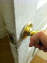
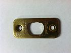
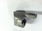
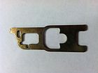
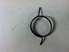
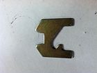
Rotating the doorknob turns a mechanism that converts rotational motion to a translational motion, which is connected to the door latch. The door latch makes contact with a metal plate to guide the door latch into place, as well as improve durability after extended operation. Springs are attached to the doorknob as well as the door latch to facilitate the knob reset.
Assembly
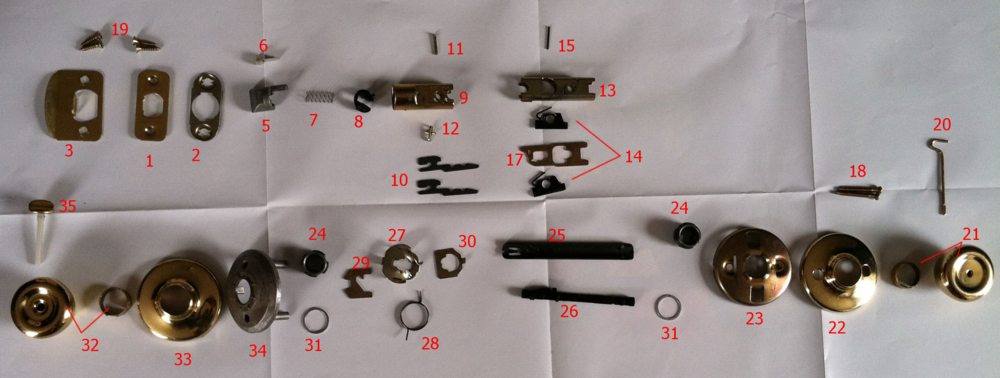
The figure below shows a fully disassembled view of the doorknob.
Figure 5.4: Disassembled doorknob
Bill of Materials
How the Product Functions Mechanically
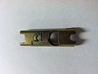
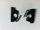
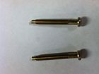
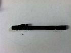
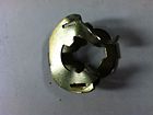
The door handle consists of three major components – the outside doorknob, the inside doorknob, and the latch mechanism. The inside and outside doorknob are connected by two throughbolts, with a quartershaft in the center. When assembled, the latch mechanism is held in place by the inside knob frame, and has the quartershaft running through it. When the doorknob is rotated, the quartershaft turns, forcing the back metal shifter to retract. The retraction causes the the latch hook to rotate backwards, which then pulls back the latch tab. Two springs are located right behind the latch tab as the restoring force in the latch mechanism.
The inside doorknob houses the locking mechanism. When the user turns the lock switch, the locking shaft rotates, causing the locking teeth to extend outward and grab onto a lip. The locking teeth then prevent either knob from turning. One important thing to note is that the lock does not prevent motion within the latch mechanism. This allows the door to close, even when the doorknob is set to lock position.
This specific doorknob has an adjustable-backset latch mechanism, which allows the user to choose the distance from the edge of the door to the center of the doorknob, also known as the backset. To change the backset from 60mm to 70mm, a pin can be adjusted to slide the back frame further out, increasing the length of the latch mechanism.
Design for Manufacturing and Assembly (DFMA)
Performing a Design for Manufacturing and Assembly (DFMA) analysis on our doorknob allows us to determine whether or not designs of the product could be changed in such a way that the cost, ease, or quality of manufacturing and assembly can be improved. In order to analyze the product, we had to dissect the doorknob, so we could at least consider the manufacturing processes that went into producing the doorknob.
The main goal of the dissection and the analysis was to identify areas of the product where we believe the designer made good decisions, or where we believe improvements could be made. Did the designer:
- design the simplest solution?
- make good cost-saving decisions?
- design for easy manufacturing?
- design for easy assembly?
The doorknob is somewhat unique in that some assembly by the customer is required, so design for assembly should take the customer's point of view in consideration in addition to the assembly plant's point of view.
The table below lists guidelines that we followed as well as our findings in this analysis.
| Design for Manufacturing Guidelines | |
|---|---|
| Minimize Part Count: | We found there to be a lot of small parts inside the doorknob, especially considering its function (open, close, lock, unlock). |
| Standardize Components: | Dissection revealed that the inner and outer doorknobs were in fact not the same part. Instead, it appears that different molds were used to create them. In general, we are looking to make the product as symmetric as possible. |
| Commonize Product Line: | It appears that most of the components are either stamped or cast. Thanks to this small number of types of manufacturing, training can be minimized, and employees become more flexible in terms of position on the production line. |
| Standardize Design Features: | Again, small differences in the design of the two doorknobs require different molds to produce each doorknob. We believe improvements can be made to use one mold for both doorknobs. |
| Multifunctional Parts: | Many of the parts inside the doorknob only serve one unique function. Moreover, each part is unique, requiring multiple manufacturing processes. Design changes should be considered to replace some of the parts with one part that performs multiple functions. |
| Ease of Fabrication: | Dissecting the product revealed that the two primarily materials used in production were mostly steel and some plastic. While switching to one material should be considered, some choices were made with a functional purpose. For example, a low-friction plastic piece on the door latch was meant to facilitate the door latch sliding on surfaces. |
| Design for Assembly Guidelines | |
| Mistake-Proof: | Some components of the doorknob, like the latch frame, are not symmetric, which makes insertion difficult during assembly. Moreover, because the asymmetry of the components are not clear enough with markings or indentations, a customer could have trouble or confusion during installation.
We also had difficulty connecting the two doorknobs to each other because they were not symmetric, and there was no clear indication for how we should connect them. We believe other customers who are installing a doorknob could run into the same problem. |
| Minimize Fasteners: | There were only two sets of fasteners in this doorknob: one set to attach the outer doorknob to its reinforced frame, and another set for the customer to install the door latch holder to the door or the door frame. |
In general, we believe there are too many parts inside the doorknob, many of which have only one function. This aspect of the product results in a complicated assembly, which leads to lower productivity. Design changes should be considered to consolidate multiple functions into one part. The end goal is to create the simplest design for the doorknob; focusing on consolidating multiple functions in one part can reduce the number of parts inside the doorknob, standardize components, and make manufacturing more cost-effective.
Secondly, we believe that the customer could face problems while installing the doorknob, because it is difficult to orient the knobs before connecting the two through the door. Making the correct orientation more obvious would reduce or eliminate this problem.
Failure Mode and Effects Analysis (FMEA)
Performing a Failure Mode and Effects Analysis (FMEA) allows us to determine potential areas of concern, particularly ways in which our product can fail. The FMEA also allows us to prioritize each failure mode. After determining the severity (S), the probability of occurrence (O), and detectiblity of failure (D), on a scale of 1-10, the three values are multiplied, which yields a risk priority number (RPN). This number is then used to order the failure modes in terms of importance. The table below shows the results of our FMEA analysis on our doorknob.
| Item and Function | Failure Mode | Effects of Failure | S | Causes of Failure | O | Design Controls | D | RPN | Recommended Actions |
| Locking mechanism | Shaft fails | User cannot lock or unlock | 7 | User turns locking lever too hard | 3 | None | 5 | 105 | Perform FEA on shaft to consider strengthening |
| Latch Turner | Pegs break under shear stress | Door cannot be opened | 7 | Age/wear | 3 | None | 5 | 105 | Perform FEA on piece to consider strengthening |
| Lock Switch | Plastic rod breaks due to torsion | User cannot lock or unlock | 7 | Excessive torque on rod | 4 | None | 3 | 84 | Perform FEA on switch to consider strengthening |
| Quarter Shaft | Tab breaks | Door cannot be opened | 8 | Excessive force from knob, age/wear | 2 | None | 5 | 80 | Perform FEA on shaft to consider strengthening |
| Doorknob | Doorknob fails | Door cannot be opened | 8 | User turns doorknob to hard | 1 | None | 5 | 40 | Perform FEA on doorknob to consider strengthening |
| Door latch | Latch spring fails | Door inoperable - fails to stay closed | 7 | Age/wear | 1 | None | 5 | 35 | Unlikely to happen over normal operating life, no action necessary |
| Door knob frame | The frame detaches from door | Creates an annoyance to user | 1 | Screw become loose | 7 | None | 2 | 14 | No action necessary - user can screw the screws back on |
The most significant failures predicted by an FMEA analysis are the result of excessive force input from the user. These items have low RPN values due to their low probability of occurence, but are still valid concerns. The components in question should be analyzed and fabricated with an appropriate factor of safety while considering possible loads on the mechanism.
Design for Environment (DFE)
DFE Analysis
| DFE Guideline | Good Aspects of Competitor Product and Ideas for Improvement |
|---|---|
| 0. New Concept Development | Cut doorknobs out of design for weight, and material savings along with durability increase. |
| 1. Select Low Impact Materials | Reduce amount of steel in the part. Use recyclable parts or plastics to reduced inputted energy.
Replace greased surface with plastic slips. |
| 2. Reduce Material Amount | Thinner cast parts. Remove outer handle.
Remove signage on product to cut down on box size |
| 3. Eco-Manufacturing |
Use outer handle for inner handle, same molds. Integrate skirt into frame. Employ electroplating for shiny surfaces. |
| 4. Optimize Distribution | Reuse packaging when distributed to contractors.
Thinner plastic packaging, stealing doorknobs is infrequent. Compress packaging to allow for better stacking. |
| 5. Reduce Use-Phase Impact | The Doorknob has very little use-impact. The only possible consumable is the grease that slicks the handle, which could be replaced with low friction slides. |
| 6. Maximize The First Life | Reduce wobbling between handle and latch.
Screw firmly into door or consider squeeze-fit to remove door failure. Simplify Compoments: Easier to Repair. Reclaimable components. Stave off the West Wing Problem: Preventing knobs from impacting walls. Sell alternate handles for same mechanism. |
| 7. End of Life | This appears to be a minimal concern due to the infrequency replacement. Assuming separable vanity handles can be used, packaging could be greatly reduced for the individual mechanism, and handles could be sold separately. |
Product Life Cycle Analysis
| Life Cycle Stage | Description | Inputs | Outputs |
|---|---|---|---|
| Material Extraction | Steel from Iron Ore
Plastic from Petroleum Raw materials must be processed. | Iron Ore
Petroleum | Steel
Plastic Grease |
| Production | Springs (Acquired)
Casting Stamping Assembling | Steel
Plastic Grease | Components |
| Use | Doorknobs, Two Woodscrews | Working Door | |
| End of Life | Retiring/Disposal | Doorknob | Landfill |
| Transportation | Truck | Fuel, Door Latches | Door Latches |
EIO-LCA
To determine the total amount of Greenhouse Gas (GHG) emissions produced by the doorknob, the Economic Input Output Life Cycle Assessment (EIO-LCA) tool was used to perform the study. We performed the EIO-LCA analysis for an economic activity of $1 million.
During its use phase, the doorknob does not emit any greenhouse gases, so the main focus should be on its production phase. The table below shows a summary of CO2 emissions during production phase.
| Item Consumed | Doorknob |
|---|---|
| Sector # and Name | Sector #33712A: Metal and other household nonupholsetered furniture |
| Reference Unit | Kwikset Tylo Polished Brass Bed/Bath Knob |
| Units Consumed Per Product Life | 1 |
| Cost Per Unit ($2002) (Retail) | $6.33 |
| Lifetime Cost ($2002) | $0 |
| Sector mtCO2e Per $1M | 810 mtCO2e |
| Implied mtCO2e per Product Life | .00645 mtCO2e |
| CO2 Tax @ $30/mtCO2e | $0.19 |
The table below shows the top 5 sectors for GHGs.
| Sector | Total tCO2e | CO2 Fossil tCO2e | CO2 Process tCO2e | CH4 tCO2e | N2O tCO2e | HFC/PFCs tCO2e | |
|---|---|---|---|---|---|---|---|
| Total for all sectors | 810 | 605 | 103 | 56 | 24 | 22.2 | |
| 221100 | Power generation and supply | 248 | 244 | 0 | 0.673 | 1.52 | 1.57 |
| 331110 | Iron and steel mills | 121 | 45.7 | 74.7 | 0.738 | 0 | 0 |
| 211000 | Oil and gas extraction | 38.3 | 10.8 | 7.01 | 20.5 | 0 | 0 |
| 325211 | Plastics material and resin manufacturing | 37.3 | 37.3 | 0 | 0 | 0 | 0 |
| 33712A | Metal and other household nonupholsetered furniture | 33.8 | 33.8 | 0 | 0 | 0 | 0 |
Results above show that the majority of GHG emissions comes from the power needed to run the plant and produce the products, followed closely by iron and steel mills, which produce the raw material needed for the doorknobs. This finding suggests that in order to improve the environmental impact of producing doorknobs, plant downsizing as well as material selection or reduction should be considered. These solutions agree with the findings of our Design for Manufacture and Assembly Analysis.
Applying a CO2 tax of $30/mtCO2e would increase the price of the doorknob by $0.19, which is not a significant increase in the price of the product, and would be a reasonable method to combat the product's GHG emissions.
Team Roles
Derek DeChamplain - FMEA
Tristram Hogben - DFE
John Ni - BOM, Disassembly
Won Shim - Team Leader, DFMA, Executive Summary
References
- Carnegie Mellon University Green Design Institute. (2012) Economic Input-Output Life Cycle Assessment (EIO-LCA) US 2002 (428) model [Internet], Available from: <http://www.eiolca.net/> [Accessed 11 Feb, 2012]
