Drink cooler
From DDL Wiki
Contents |
Executive Summary
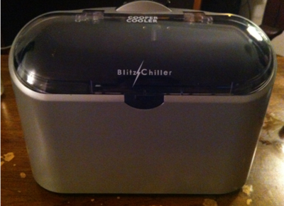
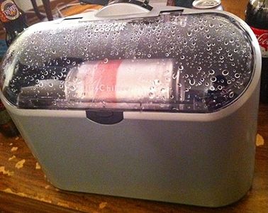
In the first phase of our design process, we analysed a competitor’s product, the “Blitz Chiller”, a drink cooler that can cool drinks in 2 to 6 minutes depending upon the drink and the container the drink is in.
Our user study corroborated the manufacturer’s claim of being able to cool a drink down in 2 to 6 minutes. However, the operation of the machine was accompanied by noisy vibrations. In addition, if bottles were used in the machine, they left visible scratches inside the machine. These noticeable defects need to be reduced.
The manufacturing process of the product is largely competent. Multi-functional parts such a single motor to control the flow of water and rotate the drink aided in reducing the number of parts used. In addition, the cost effective measure of using a large number of standard parts was implemented. However, the sluggishness of the mechanical control system may need to be eliminated by installing a toggle system. The use of press fits for fastening makes the assembly process of the product efficient. However, the use of glue for a solitary fastening operation in the product may need to be replaced to streamline the assembly process further.
The use of several safety features reduces the possibility of failures in the product. However, the possibility of water leakage inside the machine resulting in an electric shock for the user was an important failure mode we revealed. The possibility of the lid, which did not open completely, breaking and rendering the machine unusable was another significant failure mode discovered. These failure modes need to be accounted for in any further development of the product.
The product fared badly when assessed on its impact on the environment. The machine use two trays of ice to 2 cans from room temperature down to 33 ͦ F. This level of ice usage leaves a large carbon footprint and needs to be changed in order to make a more competent product.
Thus, the environmental impact of this product is something that needs to be redressed urgently. Though the product is largely well-designed for manufacturing assembly and even accommodates several failure modes, there is scope for improvement in these areas as well.
Identification of Stakeholders
End User
This is the person who will ultimately use the product. They will own and operate the product at social occasions. They want to be proud of their purchase, and enjoy the experience of using the product. The things they will look for in the product:
- Enhances ability to host events
- Short duty cycle
- Ease of operation
- Ease of setup
- Ease of cleanup
- Can operate unattended
- Liked by guests
- Cheap
- Ease of storage
- Works on arrival
- Safe
- Little or no maintenance
- Appearance fits setting
- Attractive exterior
- Does not require additional materials to operate
User’s Associations
The family, friends, co-workers, clients, and other guests whom the user is entertaining. They don’t want the product to interfere with their enjoyment of the event and they want cold beverages at all times. The things they will look for in the product:
- Does not take up space
- Low noise level
- Frees host to entertain
- Short duty cycle
- Hard to accidentally break
- Can be operated while intoxicated
Retailer
The retailer stocks and sells the product, most likely online. They want a product which customers will buy and enjoy using. The things they will look for in the product:
- Return on investment
- Easy to stock
- Inexpensive to ship
- Easy to market online
- Product experience is consistent
Marketing
The marketing staff of the company which produces the product. They have to get a retailer to stock their product. They also promote the product to increase awareness among potential customers. They are interested in maximizing profits for their company and increasing market share. The things they will look for in the product:
- Fits with brand image
- Improves brand image
- Low barriers to market entry
- Easily identifiable market
- Advantages over competitors’ products
- Easy to identify positive features
- Low potential for misuse
- Low potential for litigation
Shipping
The transportation contractors who move product from manufacturing plant to retailer’s warehouse, and from retailer to end user. They want a product which is easy to pack in large quantities, and presents no hazards to the person transporting the product. The things they will look for in the product:
- High packing factor
- Robust packaging
- Low weight-to-volume
- Low potential for damage during transit
- Low environmental needs during transit
- Not hazardous to driver
- Easy to load and unload
Product Usage
Description of Use /Steps for Use
The product, the Blitz Chiller, operates in the most general sense, by spraying chilled water over a rapidly rotating bottle or can. The goal of this is to quickly cool a beverage by inducing forced convective heat transfer using 0°C water to cause a rapid temperature decrease.
1. Place the unit on a clean, dry, level surface, insert the power adapter into the rear of the unit and plug the adapter into a suitable outlet. Press the lid latch to open the lid.
2. Add approximately one tray of ice cubes which is about 16 standard cubes into the ice-water bin. Make sure ice is not above the drive roller.
3. Pour 1.5 cups (355ml) of cold water into the ice-water bin. Make sure that the ice-water level is below the drive roller.
4. Place your drink container HORIZONTALLY onto the roller with the container neck or top facing to the left.
5. Close the lid securely. NOTE: the unit has a safety feature where the lid must be closed in order to operate. If the lid is open, the unit will not operate.
6. Slide the TIMER LEVER to the right to your desired setting to start the Blitz Chiller.
7. After the unit has reached the time allotted, make sure the motion has stopped. Depress the lid latch and the spring-loaded lid will automatically come up. - BE CAREFUL THAT YOUR HAND OR OTHER BODY PARTS ARE NOT BY OR ABOVE THE LID WHEN IT OPENS TO PREVENT INJURY.
8. Remove your beverage and enjoy.
9. Before chilling another beverage, you may need to add more ice. SEE ADDING MORE ICE & REMOVING WATER SECTION
ADDING MORE ICE AND REMOVING WATER SECTION)
Adding More Ice And Removing Water
Ice will need to be added as additional beverages are chilled. To add more ice, follow the steps below.
1. First, unplug the unit and have the lid open. Tilt the unit on its side to dispose of the excess water, BUT STILL HAVE ENOUGH WATER TO ALLOW THE PUMP TO FUNCTION.
2. Now add more ice making sure the ice water bath is not above the drive roller.
3. Continue chilling your beverages as before. If the pump is sputtering and water is not flowing smoothly from the water exit jet, just add more water until a smooth water flow is obtained.
Results of User Studies
The product was found to be a robust, attractive design, and very easy to use. Initial studies found that company claims about temperature changes for a given container and chill time were supported (Blitz Chiller). The product also lived up to claims that it would not make the beverages foamy or alter their flavor (Blitz Chiller). After a few uses, it was observed that bottles were making gouges in the end of the reservoir.
| User Study Results for Canned Beverage | |||||||||
|---|---|---|---|---|---|---|---|---|---|
| Beverage Type | Initial Temperature | 2 Minute Blitz Cooler Cycle | 2 Minutes in Ice Bath | 2 Minutes in Refrigerator | 2 Minutes in Freezer | 6 Minute Blitz Cooler Cycle | |||
| Can | 67 °F | 37 °F | 57 °F | 66 °F | 64 °F | 30.5 °F | |||
| Bottle | 74 °F | 52 °F | 66 °F | 74 °F | 74 °F | 35 °F | |||
Mechanical Functioning
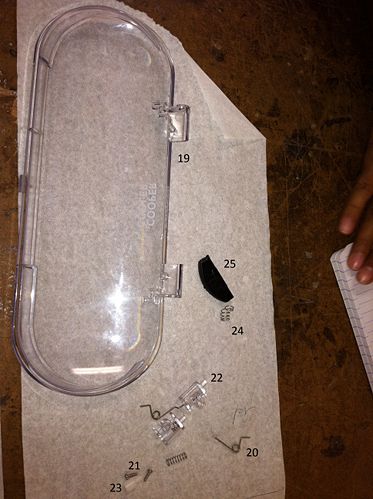
To operate the unit, must first be plugged into a wall socket. A push button latch on the front of the machine allows the user to unlatch and open the lid of the machine. The lid when shut activates a kill switch at the bottom, hence making sure the product can not run while the lid is open. Once the machine is plugged in and opened, a tray of ice cubes (approximately 16 standard sized ice cubes) is placed in the ice-water bin of the machine. One and half cups (12 oz) of cold water are the added to the ice-water bin creating an ice water bath in the bottom of the machine. The ice-water bath does not cover or touch the area where the beverage will sit. The maximum water level is approximately 1-2 cm below the beverage. This is to allow the bar that the beverage sits on to rotate freely increasing the convection co-efficient.
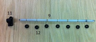
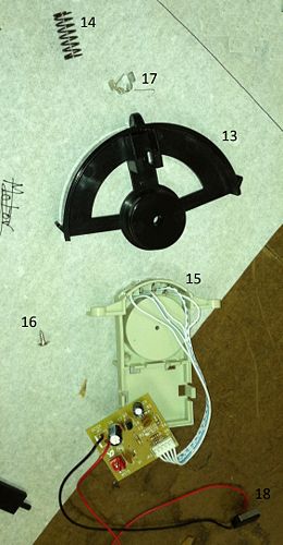
After the ice-water bath has been set up, the beverage is placed on to the drive roller in the machine and the latch is closed. The user then uses a timer lever on the top of the machine to cool the beverage for 2, 4, or 6 minutes. The timer is attached to an electronic circuit board. The driver roller is a long metal shaft that runs the length of the ice-water bin and is covered in rubber rings. These rubber rings ensure good contact between the driver roller and the beverage so that as the driver roller spins, the drink will spin with it.
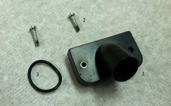
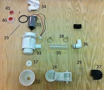
As the machine operates, the driver roller spins causing the beverage to spin quickly. Simultaneously cold water is drawn from the bottom of the ice water through a small drain and is sprayed over the rotating beverage through a water spout located in the upper middle section of the ice-water bin located above the beverage. Both the spinning and the pumping of the water are done using the same motor. The motor assembly connects to a pipe which pushes the water up to the water spout with a fair amount of pressure. Once the selected amount of time has elapsed, both the driver roller and the cold water spray stop.
Once several beverages have been cooled, more ice may be needed to refill the ice-water bin, so water in the bin may be emptied from the top of the machine to make room for more ice.
The major mechanical components are the latch and lid mechanisms, the driver roller, and the water spray and pump system.
Bill of Materials
Assembly List
Water Spout Assembly:
Bottom Assembly:
Rotary Bar Assembly:
Circuitry Assembly:
Lid Assembly:
Bottom Drain and Motor Assembly:
Entire Housing Assembly:
Parts List
Design for Manufacturing and Assembly
Many of the strengths regarding design for ease of manufacturing and assembly from the competitor's drink cooler were carried over into the proposed product. Our product incorporates many of the same parts used in the competitor product. The major difference is that our product has the additional water cooling block with the Peltier cells added in series with the competitor product's water circuit. [Accidentally edited while working on final report.]
Manufacturing
The biggest success of the competitor drink cooler was the design of the motor. One motor was designed that played a multifunctional role as it powered both the water pump and also the drink rotator. This was critical to the design as it allowed the entire product to be both compact and cheap. We had anticipated having a separate motor for each of those roles.
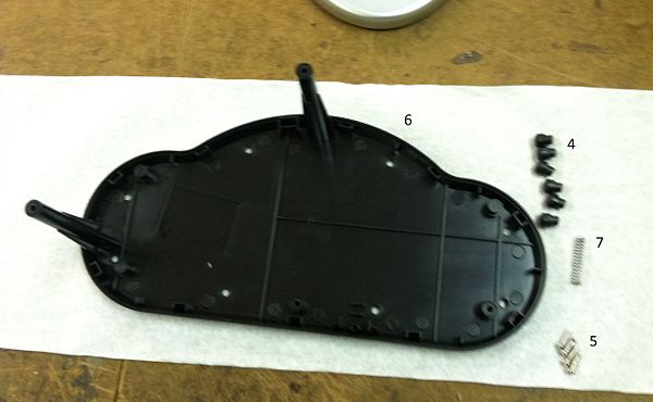
All parts in the design beyond those that would be specific to this product were standardized. The only custom parts were found to be the external housing, rotator bar, motor housing, and water plumbing. These were all made using injection molding. Considering this device will be mass produced by the company, injection molding is probably the most efficient means of production. Among the custom parts, the motor housing and rotator bar were designed such that they could also be used across other drink cooler models produced by this same company, increasing scale of production while reducing required equipment. The standardized components used in the design were the screws, springs, motor, pulley, circuit board, and O-rings. This took advantage of the scale of production. In addition, it was designed such that only one drill size was needed and all the holes could be drilled from as few positions as possible.
The only two areas weaknesses were the mechanical control system and the low construction tolerances. The control system featured several parts that had to be fitted together in a precise way. Still, the control system was very sluggish and left room for improvement. A toggle system might be a potential way to improve the design. The tolerances of the entire system were very small. This was necessary because the system needs to be water tight. This is a weakness, but will also be hard to improve on.
Assembly
The design was made in a way to ease assembly. A majority of the pieces fit into the external housing in order from bottom to top. In addition, most of the parts are press fit. These parts were designed to be round with guides. This allows for easy insertion that will snap into the correct position. These press fits also reduced the requirement for screws, which are tedious and would complicate the assembly. In addition, the water plumbing was joined with a flexible rubber connector. This improved the tolerances of the tubing. Finally, the custom parts were injection molded using two materials. One of for the external housing and one for the interior parts.
The only weakness identified was with the choice of fasteners in some cases. There is one connection created using hot glue that joins the water tubing to the inside wall of the external housing. This was likely done to reduce vibrations. However, this one connection requires the use of a completely new tool. This adds another step to the assembly process. Finding a way to eliminate the hot glue connection with either a screw or a press fit would reduce the number of tools required. This would also save time in assembly. The other weakness was that some of the screws were hard to reach. Their insertion points were at the very bottom external housing. Reaching to these locations to screw them in is inefficient. A potential solution is to either replace them with press fits or relocate the screws such that they are in a more accessible position.
Failure Mode and Effects Analysis
The Blitz Chiller has few failure modes that risk the safety of the user. The Failure Mode and Effect Analysis of the Blitz Chiller was upon Risk Assessment Analysis Tables found in Engineering Design by Dieter and Schmidt (p 708-711). The method assigned numerical values from 1 to 10 for three different risk assessment categories: Severity (How severe the effects of failure are with 1 being no effect and 10 be severe danger to the user), Occurrence (How often will the failure occur with 1 being an extremely remote chance of occurrence and 10 being an extremely high chance of occurrence), and Detection (How easily the failure will be detected with 1 being a certainly detected failure and 10 being an impossible to detect failure). For each failure mode of the product a Severity score (S), an Occurrence score (O), and a Detection score (D), were assigned the product of these three values is called the Risk Priority Number.
Based on our analysis of the Blitz Chiller, the only failure mode that could seriously endanger the safety of the user (a Severity score of 9 or 10) was the failure of internal water tight seals which could allow for the user to suffer an electric shock if the water short circuited the internal electronics.
The most likely failure, unrelated to intentional product misuse was failure of the motor due to an excessive number of cycles and wear. The motor would suffer slow degradation over time due to use and would eventually fail causing the product to become inoperable.
The most likely failure due to misuse or unintentional damage from falls would be from the lid of the unit breaking off. In the user study, it was realized that the lid did not open fully to 90 degrees and that some users may try to over open the lid causing damage to the connection between the lid and the body of the unit. The hinges that connect the lid to the unit are small plastic pieces that could fracture during a fall or strong opening force. The lid breaking off would render the product unusable because of the products built in safety feature that does not allow the product be operate when the lid is not properly closed.
Overall, the product is extremely well designed from a Failure Mode and Effect Analysis perspective and the only major area for improvement would be in the connections between the lid of the product and the main body.
| Failure Mode and Effects Analysis | |||||||||
|---|---|---|---|---|---|---|---|---|---|
| Item & Function | Failure Mode | Effects of Failure | S | Causes of Failure | O | Design Controls | D | RPN | Recommended Actions |
| Motor - Powers rotational bar and pump | Burnout | Reduced or no motor output | 8 | Heat, excess voltage | 4 | Voltage input regulator for motor | 2 | 64 | Design circuits to prevent burnout |
| Motor Shaft - Transfers mechanical power in pump | Break | No motor output, product inoperable | 8 | Fatigue | 10 | Material properties prevent fatigue failure based on life time and maximum stresses | 2 | 160 | Stronger material to reduce chances of fatigue failure. |
| Internal Seals - Prevent leakage of water into the body of cooler | Cracks and shrinks, pulling away from surfaces | Higher probability of short circuiting electrical components | 9 | Material fatigue over time | 4 | Visual inspections on line, material properties that allow for repeated thermal and stress cycling | 2 | 72 | Use materials that are not affected by sudden temperature changes. |
| Front Latch - Keeps lid of Cooler closed | Latch breaks at hinges and spring and will not keep Cooler closed | Product will not function with an open lid. Product inoperable | 8 | Fatigue or excessive stresses | 4 | Use materials that can withstand maximum expected stresses and fatigue | 1 | 32 | Use a different material for hinges, such as metal, to reduce likelihood of failure. |
| Back Hinges - Limit range of motion of lid and attach it to body | Plastic hinges break | Product will not function without a closed lid. Product inoperable | 8 | Fatigue or excessive stresses | 5 | Use materials that can withstand maximum expected stresses and fatigue | 2 | 80 | Allow for wider range of motion so that user does not try to force machine open |
| Limit Switch - Prevents product from operating without a closed lid | Switch becomes stuck always on or always off | Product may function without lid if stuck on or never function if stuck off | 9 | Fatigue | 3 | Design limit switches to survive lifetime of product without failure | 2 | 54 | Test limit switches to ensure they will survive necessary number of cycles |
| Connector - Connects front latch mechanism to limit switch to indicate if lid is closed | Breaks along length or at ends and becomes misaligned | Product may function without lid if stuck on or never function if stuck off | 8 | Stress or impacts | 3 | Simple design minimizes pieces that can become misaligned | 2 | 48 | Ensure that connection is not easily broken in small drops or impacts |
| Timer Wheel - Completes electric circuit and allows user to select how long the production functions for | Internal spring becomes jammed, preventing the user from changing the setting of time | User may be unable to turn on or off machine, or change time settings | 8 | Impacts or fatigue | 3 | Simple design minimizes parts that can become stuck or fatigue | 2 | 48 | Ensure that materials chosen can withstand expected stresses and fatigues. |
| Beverage Bar - Supports beverage and spins the beverage during operation | Bar fractures along length | Unit will become inoperable | 8 | Excessive force | 3 | Metal rod through center of beverage bar increases strength | 1 | 24 | Proper supports on end of may help to reduce stress along bar when loaded |
| Beverage Bar O Rings - Attached to bar and increase friction between bar and beverage to promote rotation | O Ring surface wears away over time | Unit will less effectively spin the beverage | 5 | Prolonged use over time | 2 | O Rings sit in a recessed groove to ensure they remain in place to contact beverage even if surface degrades | 2 | 20 | Better material selection for O Rings may reduce degradation of surface of O Ring over time |
| Gears - Transfer motion of motor to beverage bar | Gears may grind becoming misaligned | Unit will function sub optimally and produce undesirable noises | 7 | Prolonged use over time | 4 | Use of rubber belts will reduce potential for build up of stress in gears, belts will slip first | 1 | 28 | Better material choice for gears can reduce degradation of gears over unit lifetime |
Design for Environment
When we tried to compute the impact the product had on the environment over the course of its lifetime we considered the material extraction, production, use, end of life and transportation of the product. We did a green house gas impact analysis using the EIOLCA tool separately for the production and the use of the product.
Production
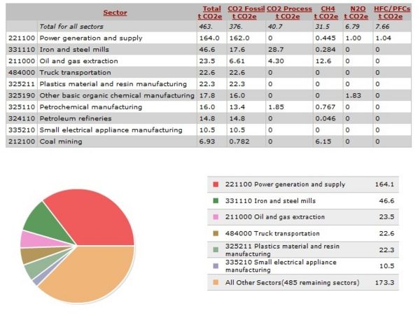
For the production section we used the Small Appliances Manufacturing(335210)sector. Given that one product costs about $40 at retail. Running the model for this sector we found that for every $1 million spent on manufacturing the plastic product 463 metric tonnes of CO2 were released. The break up for each sector is below. Scaling this down for $40 we found that through the life cycle of this product it uses 0.019 metric tonnes of CO2 which @$30 tax a metric ton works out to be $0.56. Hence the greenhouse gases emitted when manufacturing the product is not that significant.
Use
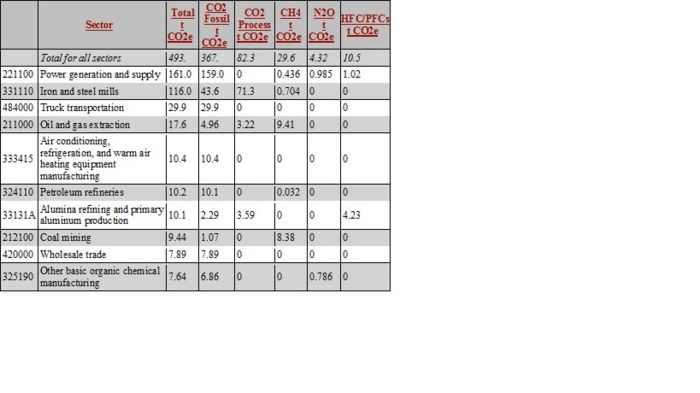
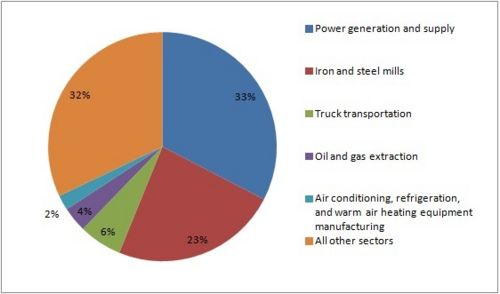
Our product uses a lot of ice, which is used to cool the beverage down to the required temperature. During the user study we found that one tray of ice cools about 2 cans effectively before warming up to an unusable degree. We estimate that about 1000 trays of ice will be used in the lifetime of the product. This is a significant amount of ice to be made using refrigeration. For the production of ice we analysed the Air Conditioning, Refrigeration and warm air heating equipment sector and the results were as shown in the table and graphs below. Using the cost of ice at Giant Eagle we estimated that one tray of ice costs 50 cents. Hence we will use $500 of ice over the lifetime of the product. Based on that fact that 493 mt CO2 are released for $100000, for $500 of ice, the product uses 0.2465 mt CO2. At a tax of $30 per mt CO2 this works out to be a significant amount of $7.395.
Overall Analysis and Conclusions
The carbon dioxide tax would make a significant impact on the cost of the product. The highest contributor to the tax is power generation and supply which contributes over 32% of the emissions with other sectors as iron and steel mills contributing 21%. However other than these two sectors all other sectors contributed less than 5% of overall emissions. We found that the overall tax on the product due to CO2 emissions was fairly significant mostly due to the production of ice. The using of ice contributes to 99% of the environmental impact the product has. Hence for the next steps of our project we will like to increase the thermal efficiency of the product and reduce the amount of ice while cooling.
Team Member Roles
The team worked together effectively in carrying out the tasks. We all scheduled weekly meetings where we would report our findings from the previously assigned tasks and divide new tasks to be completed by each individual for the next meeting. This approach seemed to work well for our group and we plan on using a similar approach as we go forward with the project.
Phase I team roles:
- Team Leader - Dhruv Swaroop
- DFMA Leader - Ojas Mainkar
- FMEA Leader - Robert White
- DFE Leader - Arvin Sabu Joseph
- Presentation Leader - Charlie Munoz
References
- "Blitz Chiller." Blitz Chiller. Web. 10 Feb. 2012. <http://www.blitzchiller.com/>.
- "Blitz Chiller Model HC03 Instruction Manual." Print. 12 Feb. 2012.
