Iron
From DDL Wiki
Contents |
Executive Summary
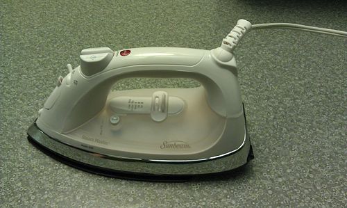
In the study of our product we took into account the manufacturing process, the effects on the environment and potential failure modes(DMEA,FMEA,DFE). In our analysis we discovered that our product, the Sunbeam Iron (model number 3017), was built using simple mechanisms and was designed fairly efficiently. Irons have been around for a long time and current manufactures have done an exceptional job at simplifying the assembly process. Despite the extensive history of the iron there still is room for improvement. A few major imperfections we noticed were unnecessary wire guards, sturdier water tubes that will reduce manufacturing error and eliminate the need for spring to protect the tubes, and similar valves that can be standardized into one design.
In our study of the iron we analyzed failure modes. Our product contains a few parts and therefore most of the failure modes involve safety concerns and electronic failure. Some safety concerns include the failure of the electronic timer which controls the power going to the base plate, failure in the temperature sensitive switch mechanism, and hot water leaking out of the steam outlets. Some of the consequences of these failure modes are the base plate over heating, the user getting burned, or iron not being the right temperature needed to use on the desired fabric. Some suggestions we have for improving the iron based on these failure modes are that some components that could utilize better materials, and that some mechanical components could be replaced with electronic alternatives.
When studying the environmental effect we took the following into account; manufacturing, the resources used and produced, and its life span. The manufacturing portion has the greatest effect on the environment. 0.02 metric tons of CO2 are produced as bi-product of manufacturing the iron. As a result the amount of tax that should be added to compensate for this pollution is around 60 cents. This is not significant relative to the price of the iron and the manufacturing costs. Improving the manufacturing would also, as a result, decrease the environmental effects. Some ideas we came up with were to standardize the parts to remove unnecessary confusion when assembling and to make the base plate thinner to decrease the time it takes for it to heat up. Other ways that the iron could be made more environmentally friendly is to optimize the heat distribution of the base plate and to reduce the length of the auto-off timer which would minimize the power usage. We also thought about make the iron easily recyclable but assembling it using a design that would also make it easy to disassemble.
Product Stakeholders
Stakeholders Major stake holders for our product would include: dry cleaners, home cleaning services, busy mothers, iron manufactures such as Black & Decker and Sunbeam, and major department stores.
| Stakeholder Needs | |||
|---|---|---|---|
| Stakeholder | Consumer | Needs | Wants |
| Consumers |
|
|
|
| Retailers |
|
|
|
| Manufacturer |
|
|
|
| Transportation and Shipping |
|
|
|
Iron Use
1. An iron is used to remove wrinkles from clothing through use of force, heat, and steam. Once plugged in, the temperature can be set to optimally heat specific fabric types to make them plyable and therefore bend the individual fibers into a flat shape, removing wrinkles. The ironing board provides a flat surface on which to press the clothing under the iron. It also provides a surface on which an iron can contact with a relatively low coefficient of friction, but has a high coefficient of friction between fabrics.
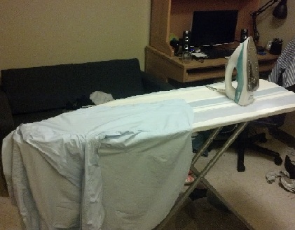
Iron Pre-Use
2. The iron is pressed down on clothing. Heat and applied force from the flat, hot plate removes wrinkles by heating individual clothing fibers and bending them straight. The ironing board provides a flat surface to run the iron across. Pressure is applied manually from the user to flatten wrinkles. Water can be spritz onto clothing to increase fabric maleability using a spray button on the top of the iron. Water is sprayed out of the nozzle on the front of the iron and onto the clothing.
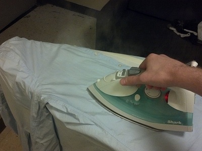
Horizontal Iron Use
3. Vertically hanging clothing with wrinkles can be treated using forced steam. The iron produces forced steam which is capable of heating and treating vertical clothing with no ironing board for clothing that does not need pressure to remove wrinkles. The steam function does not extend a great distance, which means that the risk of scalding one's hands is minimal. By pressing the steam button on the iron, a plume of steam is produced on the underside of the iron.
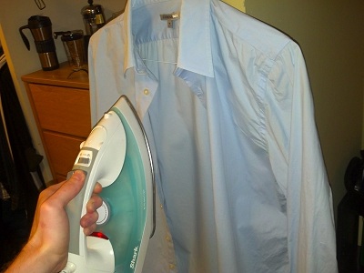
Vertical Steam Function Use
Product Mechanical Function
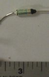
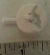
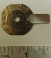
An average iron uses many mechanical systems to provide water to a hot iron base plate. The particular iron we dissected revealed three main mechanical systems. The first mechanism is the steam mechanism which utilizes pump and a compression spring. When the steam button is pressed a pressure gradient is created and the water is pushed up and out into a tube that leads to a drip nozzle. The second mechanism is the temperature sensor control. This is mechanism uses a FPA223-80 temperature sensor that expands and flips a switch when the temperature reaches just over the boiling point. The switch gets flipped and pushes on the bottom of the drip nozzle. On top of the drip nozzle is a compressive spring that get compressed which allows for water from the steam tube to flow down into base plate. Therefore when the temperature of the plate surpasses the boiling point the water from the steam tube is allowed to move toward the hot iron plate to get vaporized. The clean button mechanism works in a similar fashion except the compression spring has a different stiffness so that all the water in the water reservoir is allowed to flow out. The third mechanism is the temperature control/selector mechanism utilized in fabrics selection. The temperature is modified by changing the resistance in the heating mechanism. This is accomplished when the user picks a fabric by using the slider that moves horizontally. Underneath the slider is a circular attachment that converts the translational motion into rotational motion. This rotational movement rotates the resistance modifier mechanism which will either add or subtract resistance to the depending on whether it need to get hotter (add resistance) or colder (subtract resistance). Another basic mechanism that this iron uses is a reset feature. This reset features uses a button pressing mechanism that resets the circuit that controls the power of the heating element. When the reset button is pressed a pin hits the circuit and which resets the power to the heating element.
Assembly
This Iron was the cheapest model on the market. As the least expensive model in a competitive commodity market it was designed to be very cheap to manufacture. Ever aspect of its manufacture was designed to be cheap to make and assemble. Most components are injection molded with no post process modification. Particularly well designed are the sealed chambers. The Iron has sealed fluid reservoirs, the water reservoir and the steam reservoir. Both are made using a bottom plate with a thin track. This track is filled with an adhesive, epoxy for the water reservoir and silicone for the steam reservoir. As a track, it can be filled with little risk of spillage or clean up. Once filled, the top piece is pressed into it, forming a sealed bond. In addition to such innovations the iron is designed as a series of layers, to be build one on top of the other in a sequential assembly which must reduce cost.
Sub-Assembly
Where possible, the Irons design used sub-assemblies to reduce costs. The mister uses pre-assembled connecting tubes and seals. The seals for other systems such as the cleaner are also pre-fabricated. The entire system is controlled by a mechanical heat control that is assembled elsewhere and added as a unit. Similarly the electronic timer is inserted as a completed piece. The piston controlling the steam flow is also a separate pre-designed and constructed system.
Bill of Materials
The following is a table of individual components that can be found within the iron that was dissected. Most parts have been stripped to the individual components, but some remained in assembly form as further dissection would have been unnecessary.
| Part Number | Name | QTY | Weight (g) | Function | Material | Manufacturing Process | Image |
|---|---|---|---|---|---|---|---|
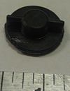
| 1 | Atomizer | 1 | 0.5 | Sprays a mist over fabric when activated | Plastic | injection molding | |
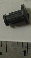
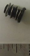
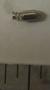
| 2 | Ball bearing spring mount for pump | 2 | 0.5 | creates mounting point for spring | Steel and plastic | off shelf and injection molding | |
| 3 | Bottom Cover of Handle | 1 | 24 | Acts as container for electronics and buttons in addition to physical structure and handling | plastic | injection molding | |
| 4 | Bottom plastic housing | 1 | 144 | Insulator to keep heat from other components | plastic | injection molding | |
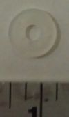
| 5 | Brass washer | 1 | 0.5 | helps create seal in steam control system | brass | die pressed | |
| 6 | Cam Housing Mounting Bracket | 1 | 2 | Holds cam in position and bolts steam control in place | plastic | injection molding | |
| 7 | CBS base | 1 | 0.5 | Physical structure for seal | plastic | injection molding | |
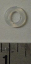
| 8 | CBS seal | 1 | 0.5 | O-ring to prevent water flow | rubber | injection molding | |
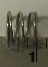
| 9 | CBS spring | 1 | 0.5 | Maintain pressure on O-ring | Steel | Bending wire | |
| 10 | Clean button seal | 1 | 1.5 | Opens to flush water through system to clean it | steel, rubber, plastic | Assembly | |
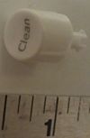
| 11 | Clean Push Button | 1 | 0.5 | activates 'clean' function on iron | plastic | injection molding | |
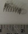
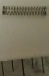
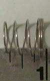
| 12 | Coil spring at base of pump | 2 | 0.5 | Holds pump head under pressure | Steel | Bent wire | |
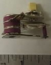
| 13 | Control Potentiometer | 1 | 35 | adjusts current cut-off to control temperature | Various alloys | Assembly | |
| 14 | Crimp connector | 3 | 0.5 | connects leads from e-board to hot plate | plastic | injection molding | |
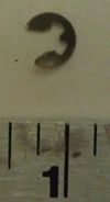
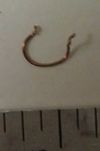
| 15 | E clip | 1 | 0.5 | Holds spring in Steam control in place | Steel | die pressed | |
| 16 | Electronics Assembly and Leads | 1 | 22 | controls auto-turn off feature of iron | PCB & components | Assembly | |
| 17 | Handle top cover | 1 | 26 | Smooth surface for ease of use | plastic | injection molding | |
| 18 | Heater wire insulator assy | 1 | - | Protects wire from heat damage | Aluminum, Plastic | Assembly | |
| 19 | Heater wire lead | 1 | 3 | connect control pot to hot plate | copper & insulation | off shelf | |
| 20 | Heating diode | 1 | 2 | controls current flow into heater | silicon | off shelf | |
| 21 | Hot plate | 1 | 464 | heated part of iron | Steel | cast | |
| 22 | HWIA insulator clip | 1 | 1 | attached insulation to hot plate | Steel | die pressed | |
| 23 | HWIA insulator tube | 1 | 3 | insulates heating wire from hot plate | plastic | Extruded | |
| 24 | Metal aesthetic cover | 1 | 74 | gives iron aesthetic appead | Steel | Cast | |
| 25 | Metal rod for steam selector rocker | 1 | 1 | holds steam selector cam in position and allows for rotation | Steel | extruded | |
| 26 | Mister and Steam buttons | 2 | 3.5 | user input to either mist or steam cloth | plastic | injection molding | |
| 27 | Mister assembly | 1 | - | Provided's water for misting | springs, tube, mister | Assembly | |
| 28 | Mister hose | 1 | 0.5 | allows for water to flow from pump to mister | rubber | extruded | |
| 29 | Mounting bracket bottom | 1 | 2 | holds selector cam mount to rest of iron assy | plastic | injection molding | |
| 30 | Pinion Gear to Attach to Potentiometer | 1 | 1 | pinion to adjust temperature of iron | plastic | injection molding | |
| 31 | Pinion pot adapter | 1 | 1 | converts pinion output to potentiometer input | plastic | injection molding | |
| 32 | Plastic sleeve around electronics | 1 | 0.5 | insulates electronics pcb | plastic | extruded | |
| 33 | Power Cord Bend/Kink Protector | 1 | 4 | prevents power cord from kinking & allows for rotation | rubber | Injection molding | |
| 34 | Power Cord | 1 | 128 | Connects to outlet to provide power | copper & insulation, plastic, steel | Assembly | |
| 35 | Pump cylinder | 2 | 0.5 | functional part of mister/steamer, user depresses pump moving water from reservoir to appropriate output | plastic | injection molding | |
| 36 | Rack and Pinion Positioning Spring-Loaded Pin | 1 | 0.5 | allowd for set positioning of temperature select rack | Steel | Bent wire and cast | |
| 37 | Rack | 1 | 1.5 | transfers selector position to pinion | plastic | injection molding | |
| 38 | Rear screw | 1 | 0.5 | Connects handle together | Steel | cast | |
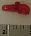
| 39 | Red Reset button | 1 | 0.5 | user input to reset the auto-off timer | plastic | injection molding | |
| 40 | Selector Handle Linear Slide | 1 | 2 | user-input to position temperature control setting | plastic | injection molding | |
| 41 | Selector Labelled With Notches for Fixed Positions Settings on Rack | 1 | 1.5 | temperature select settings visible to user, attached to rack with positioning grooves on bottom | plastic | injection molding | |
| 42 | Spring inside pump | 2 | 0.5 | resets pump to state of expansion to fill pump reservoir with more water | Steel | Bent wire | |
| 43 | Steam Selector Cam With 4 Positioning Grooves | 1 | 1 | allows user to select how much steam to release on iron | plastic | injection molding | |
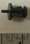
| 44 | Steam Selector Piston Gauge | 1 | 3 | adjusts opening at base of steam reservoir to change amount of steam outputted | brass | cast | |
| 45 | Steam Selector Tensioning Spring | 1 | 0.5 | keeps pressure on selector piston to prevent improper settings | Steel | bent wire | |
| 46 | Steam selector tube springs | 2 | 0.5 | prevents kinks/bends in tubes to mister/steamer | Steel | bent wire | |
| 47 | Steam tube | 1 | 2 | connects steamer pump to steam reservoir & output in bottom of iron | plastic | extruded | |
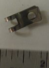
| 48 | Thermo-sensitive plate | 1 | 0.5 | temperature sensitive material and geometry to 'activate' at selected temperature setting | heat sensitive alloy | die pressed | |
| 49 | Water reservoir clear top cover | 1 | 54 | displays to user how much water they have put into the iron | plastic | injection molding | |
| 50 | Water reservoir outer hatch | 1 | 2 | opens to allow user to put water into reservoir of iron | plastic | injection molding | |
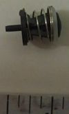
| 51 | Water reservoir seal assembly | 1 | 1.5 | opens and closed water flow based on temperature by being connected to heat sensitive plate | steel plastic rubber | assembly | |
| 52 | WRS base | 1 | 0.5 | basic structure of seal | plastic | injection molding | |
| 53 | WRS seal | 1 | 0.5 | O-ring seals water flow | rubber | injection molding | |
| 54 | WRS spring | 1 | 0.5 | holds pressure on O-ring | Steel | bent wire | |
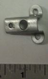
| 55 | aluminum brace | 1 | 0.5 | hold wires in place | aluminum | die pressed & formed | |
| 56 | Rubber orange dirt seal | 1 | 4 | Holds water flow to steam chamber components and keeps them water tight | rubber | injection molding | |
| 57 | Plastic bottom seal | 1 | 2 | Holds the rubber seal in place and attaches it to structure | plastic | injection molding | |
| 58 | White plastic bottom cover | 1 | 55 | bottom half of reservoir, attachment points for pistons to draw water into them | plastic | injection molding | |
| 59 | Brass wire support | 1 | 0.5 | clamps tubes to connections, keeping them water tight | brass | extruded | |
| 60 | White silicone linear seal | 1 | 0.5 | Holds base support (#8) in place to metal base (#31) | silicone | extruded | |
| 61 | White clip | 1 | 0.5 | Holds base support (#8) in place to metal base (#31) | silicone | extruded | |
| 62 | Small silicone seal | 1 | 1 | keeps wire ends water tight as they connect to heating resistor | silicone | injection molding | |
| 63 | Screw 2 | *** | 0.5 | connecting | Steel | purchased | |
| 64 | Screw 3 | *** | 0.5 | connecting | Steel | purchased | |
| 65 | Screw 4 | *** | 0.5 | connecting | Steel | purchased | |
| 66 | Screw 5 | *** | 0.5 | connecting | Steel | purchased | |
| 67 | Screw 6 | *** | 0.5 | connecting | Steel | purchased |
Design for Manufacture and Assembly (DFMA)
The low cost iron was designed in with DFMA as a central idea in many ways. It seems to have taken priority over all other features of the design, which makes sense for the lowest cost model.
This Iron was designed to be assembled by low cost, low skill workers as part of a assembly line. Each of its components is built so that vast numbers can be made cheaply.
Manufacturing
Much of the components in the iron were injection molded. This is often the cheapest method of manufacture. The larges deviation is the Iron plate itself which was cast from a quite complicated mold. It seems likely that the metal plate, as one of the most sophisticated and expensive parts of the assembly is a multi-use design, where the same iron plate is used for a range of differently priced irons created under this brand. After injection molding, the second most common fabrication is the bending of wire to form springs. The Iron has a number of different springs performing different functions designed for different shapes and spring constants. Several different gauges of wire are used in this process.
| Design for Manufacturing Features and Improvements | ||
|---|---|---|
| Design Objective | Strengths | Areas of Improvement |
| Minimize Part Count |
|
|
| Standardize Design Features |
|
|
| Keep Designs Simple |
|
|
| Multifunctional Parts |
|
|
| Ease of fabrication |
|
|
| Avoid Tight Tolerances |
|
|
| Minimize Secondary & Finishing Operations |
|
|
Assembly
The Iron was built as a series of plastic pieces, snapped together in sequence with screws to secure the connections between each layer. In-between layers, smaller components build up the mechanism of the Iron. Iron plate, metal cover, insulating plastic, middle plastic, water reservoir bottom, water reservoir top, bottom of handle, and finally top of handle.
| Design for Assembly Features and Improvements | ||
|---|---|---|
| Design Objective | Strengths | Areas of Improvement |
| Minimize Part Count |
|
|
| Minimize Assembly Surfaces |
|
|
| Use Sub-assemblies |
|
|
| Mistake-Proof |
|
|
| Minimize Fasteners |
|
|
| Minimize Handling |
|
|
| Minimize Assembly Direction |
|
|
| Provide Unobstructed Access |
|
|
| Maximize Assembly Compliance |
|
|
Failure Modes & Effects Analysis (FMEA)
The electric charge supplied to the plate’s heating element first runs through a set of electronic controls that act as an electronic timing circuit. These controls cut power to the plate after an amount of time set by the manufacturer. The cycle can be reset by pressing a red button placed on the handle of the iron. Should the electronics fail to turn the plate off, or if the electronic circuit becomes damaged, it is possible that the plate will remain hot past the time that the manufacturer has deemed safe. This failure mode can have several effects including burns to the user, damage to clothing, or damage to the iron itself should the plate become too hot for an extended period of time thus causing high thermal stresses to internal components. The severity of these effects can vary, but since harm to the end user is possible this failure mode should be considered severe. Failure of this type could be caused by external damage to the circuit board such as water or extreme heat, or by a self-contained failure such as a broken solder connection or a burned out resistor or similar component. The probability of a failure of this type appears to be low as the electronics are very simple and well insulated as to protect from external damage. There is a temperature selector on the plate itself which would protect the plate from becoming too hot for a long period of time. It would be hard to improve upon a system like this, since electronic controls are cheap and proven to be effective. However, it should be ensured that the controls are well insulated and protected from external damage.
The temperature of the plate is controlled via a mechanical, temperature-sensitive switch that closes when the temperature is below the desired value and opens when the desired temperature is reached. If this switch becomes damaged in some way, or fails to open or close, the temperature could differ from what is desired. Failure of this type could result in a plate which is too cold, or one that is too hot. A cold plate poses no severe problems to a consumer apart from having a broken iron, but a plate that is allowed to continue to heat up could become hot enough to burn the user, clothes, or potentially start fires. Though this is a severe mode of failure, the switch is internal to the iron and therefore completely unexposed to outside conditions. Also, the switch appears to be very well manufactured and sturdy, thus limiting the rate of a failure of this type. There are no controls in place to limit this failure, though unplugging the iron from the wall is a suitable way to discontinue the heating of the hot plate. Though extreme heat is a concern, electronic controls may be a better way to control heat to the plate as they are less susceptible to mechanical failure.
The water in the reservoir can be released into the steam chamber of the hot plate via two spring loaded valves in the bottom of the water reservoir. Should either of these valves open when it is not desired, it is possible that too much water could be released into the hot chamber near the plate. If enough water is released into this chamber, it is possible that hot, unevaporated water could leak out through the holes in that plate that are intended for steam. This could cause scalding and burns for the user if the water somehow came into contact with their skin. The severity of this failure would be very severe since it directly results in danger and injury to the end user. This failure mode could be caused by a broken spring in the valves, a crack of leak in the seal around the opening of the valve, or by a faulty button that causes either valve to stick open. Although it is possible for the valve to break in some way, the design of the steam chamber is such that the danger of unevaporated water leaving through the steam holes is very small. Water has to pass over a large distance of hot metal in order to reach the exit holes and by then it is very likely that all the water will have been converted to steam. This water flow design acts as a control to prohibit water from leaving the steam chamber before it has been completely evaporated. This problem could be further improved by designing the valves to be more reliable, or by adding designs to the steam chamber to further prohibit water from leaving as liquid.
The heat to the plate itself is supplied by a large resistor attached directly to the plate that acts to convert current into heat. The heating element is connected to charged leads at the rear of the plate that get power from a wall outlet. If these leads were to become disconnected, it could create a short across the conductive plate instead of passing through the heating element. Failure of this type could cause the plate itself to become charged with the voltage directly from the outlet, or even possibly to be super-heated because of the large amount of current passing through the plate. This failure would be extremely serious because of the danger of electrocution or severe burns. It could also cause a home electric breaker to trip causing problems in the wiring in the house. This failure could be caused by a bad connection at the heating element. There are no controls to stop this failure, but the connections are very solid and well insulated so the likelihood of this failure is very low. The only way to improve upon making this failure less likely is to connect the leads to the heating element more securely, but the connection is already very solid.
The water that is sprayed through the atomizer and that is used for the vertical steaming feature is supplied by two small pumps that draw from the water reservoir. These pumps direct water either through the atomizer or down in the hot section of the iron to create steam. These pumps are completely mechanical, thus they are prone to failure if any of the moving parts should break. This could cause a failure for water to be driven to the nozzle or steam chamber. This failure is not very severe are it would not cause anything beyond a loss of functionality to the iron. The cost of this failure would only amount the cost of a new iron. These pumps could fail if the plastic of the piston broke, or if the seals at the base of the pump became cracked or if any holes formed. Since these are the most heavily used mechanical component in the iron, the likelihood of failure on these parts is the more likely among the iron components. No controls exist to alleviate the probability of failure, except for a spring on each of the tubes to stop any kinking or tearing. The frequency of this failure mode could be improved by making pump components that are more durable and reliable than the plastic pumps that the current design uses. It could also take advantage of smaller, electric pumps in lieu of manual pumps in order to remove human error from depressing the piston of each pump.
When the iron is held horizontally and when the plate has reached sufficient to produce steam, water is directed across the plate heating element and through a steam chamber in order to vaporize water to steam the clothes as they are ironed. The rate at which steam is produced is controlled by a mechanical selector on the handle of the iron which controls the flow rate of water to the heating element. The selector is completely mechanical and therefore failure could be caused by any one of the many components breaking or getting stuck. Effects of this failure could include an incorrect amount of steam to be produced: either far too much or none at all. The severity of this failure is minimal since it would not likely cause any damage or physical harm to the user. Failure could be caused by any of the parts, such as the pin or piston breaking. As all of the parts are mechanical in nature, failure of this type can be fairly common and no controls exist to prohibit this failure. However, water will not be released at all unless there is sufficient heat to produce steam. This component could be improved by changing the way in which the water flow is controlled. It would require a re-design of the sub-assembly, however there may be a simpler and more efficient way to control the water flow.
Design for Environment (DFE)
In analyzing our product, we were asked to consider its design and the impact design choices made on the environment. We used the Environmental Input-Output Life Cycle Analysis tool to analyze the production process of an iron and the use cycle of the products that are used in the operation of an iron (mainly water and electricity). The table below gives a rough estimate of the CO2 equivalent produced by the production and use cycle processes and the tax that would be implemented for each process. The end of the product’s life was not considered in the EIO-LCA analysis.
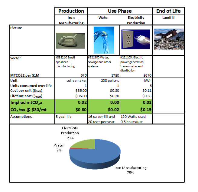
By observing the table and subsequent graph, the process that seems to be have the greatest CO2 impact and largest tax is the actual iron manufacturing, or the production phase. This result makes sense as the iron manufacturing process utilizes other sectors of the economy that have high environmental impacts.
Production
Iron production produces the greatest cost to the environment and therefore has the largest tax of any phase of the product’s life cycle. Iron manufacturing employs many other sectors of the economy. For our EIO-LCA analysis, we looked at the environmental impact of only $1 million economic production. The figures below provide a rough idea of what sectors are most involved in the small electrical appliance manufacturing, of which household appliance manufacturing composes only 5.14% (http://bea.gov/industry/io_benchmark.htm#2002data). When observing the following figures, it is important to remember household appliance manufacturing is a relatively small percentage of the entire sector represented.
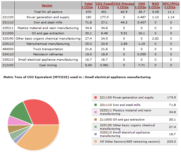
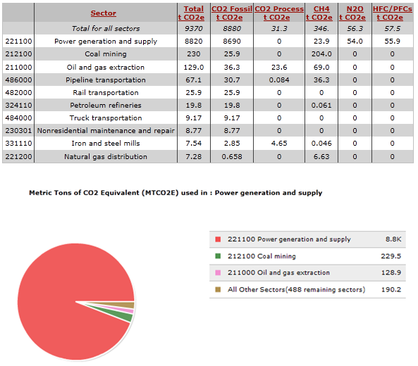
As depicted, the power production and supply as well as the iron and steel mills sectors both contribute to the largest percentage of CO2 equivalent released to the environment. Assuming that iron manufacturing composes all of the household appliance manufacturing sector, irons themselves would have an almost negligible environmental impact. However, the overarching sector does have a significant effect on the environment. We also ran the EIO-LCA model for the purchaser model and economic inputs to gather a realistic picture of the effect iron production would have on the environment. The figures shown below depict an annual economic model using the following assumptions:
U.S. Census Bureau – 115 Million U.S. households
Assumptions:
• Average life of iron is 5 years
• Each iron costs $35
• Each household in U.S. owns one iron
With these assumptions, we found the economic input of the model to be $800 million. The environmental impact of this model is shown below.
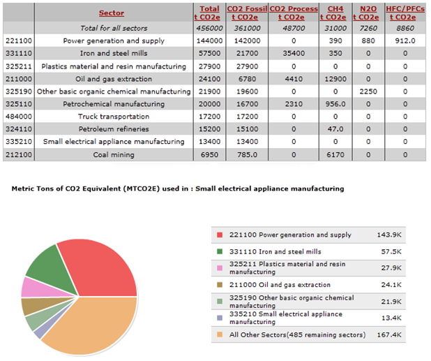
The pie chart depicting the sectors with the greatest environmental impact remains the same with power supply and generation as well as iron and steel mills dominating the percentage of CO2 equivalent in iron production. However, the overall CO2 equivalent is much greater. While an analysis of the entire iron sector was not required, our team believed an overall look at iron production in the U.S. could provide a scale to observe what a small change in the DFE of an iron would do on a large, entire sector scale.
When analyzing and dissecting our product, it was determined that production effects on the environment could be mitigated through several methods. One method would be to completely eliminate the need for an iron in the first place. This would involve new design choices by clothing stores, like wrinkle-free shirts. Also, vacuum sealed press methods could be developed that simply require a vacuum cleaner and plastic. These are radical methods in designing for the least environmental impacts, but they are viable.
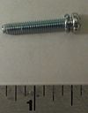
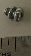
Less radical methods to reduce iron production effects on the environment lie in the design of the iron. Many of the parts we found in our dissection of an iron are very similar to each other, but are different enough that identical production methods could not be used. If many of the parts in the iron could be standardized, it would greatly cut down the amount of production time needed for each iron and lower environmental impacts. There are a few custom parts that would not be able to be standardized. For example, a spring used to control the water level from the reservoir must be at a very specific spring constant in order to operate correctly. If it is too stiff, no steam would be produced and if it is too loose, water would drip out of the iron instead of steam. This is only one example where a custom part is needed, but there are many other areas of the iron design where standardized parts would prove useful. An example of where standardization would lower production costs to the environment would be in screw choices. There are 6 different screws with the same radius that vary 1/16 of an inch from each other. Having all of those screws at the same size seems like it would be a relatively easy design change and would reduce the environmental impact of production of the iron.
Another method we discussed to mitigate environmental impact during iron production is to reduce the thickness of the iron plate itself. As the graph shows, the iron and steel mill environmental impacts are a significant portion of the total environmental impacts caused by iron manufacturing. By reducing the thickness of the plate, or even making the plate more porous, this sector could be reduced in iron production. This design choice would have to be carefully monitored and researched as the effectiveness of the hot iron plate could not be compromised. However, we do believe that the iron plate itself has the greatest potential for innovation when designing for the environment.
Use Phase
The use phase of an iron only consists of two main parts: power and water. However, each of these are minimized by what we assumed to be actual iron usage per year. These assumptions are stated in the overarching DFE table. Using the EIO-LCA tool, purchaser model, and an economic input of $1 million, the environmental impact of both power and water consumption were estimated. The following graphs show the EIO-LCA tool's output for both sectors.
Water Consumption
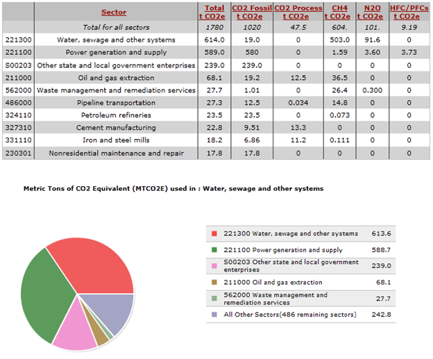
The above figures display the environmental impacts in terms of CO2 equivalent for both identified use phase sectors. However, when looking at the overarching environmental impact chart above and the percentages each use phase sector accounts for, the environmental impact is not large over the life of an iron. When designing the iron for the environment, we found that it is much more important to design for the production phase than the use phase. That being said, we still found a few alternative design choices that could reduce environmental impact in the use phase, though a more thorough cost-benefit analysis may prove that a design change could cause greater environmental impact.
The main larger of the two use phase sectors, electricity production at 23% of an iron's life cycle, is the one on which we decided to concentrate. Only 120 watts are used during iron use. This voltage is assumed to be AC and is provided by a simply wall plug in any house. It must both heat the iron and run a simple electronic assembly with a clock for the auto-off function. Because the electronic assembly is so simple, we assume that most of the power is run directly into a heating element using a thermally controlled resistor to reach various heating temperatures. The heating element design is well designed already, but we believe there is still room for improvement in both the thermal conductor that runs through the iron plate and in the plate itself. An unidentified powder runs along the heating element to shield the plate from direct electrical contact with the power wire, but it allows for conduction to occur. If it is possible to find a better insulator/thermal conductor for the heating element, that would cut down on power needed to run the iron. Also, the iron plate design is not optimal for heat distribution. Most of the heat is concentrated around the perimeter of the bottom of the iron plate. A redesign of the plate could result in better heat distribution over a large area. Lastly, the auto-off timer could be lowered so the clock does not have to run as long as it does. All of these improvements could be made to reduce electricity consumption when operating the iron.
End of Life
Though the end of life analysis is not considered in the DFE overarching chart, we believe an improvement could be made in the design of the iron to reduce waste going to a landfill. Through the dissection of the iron, we found that an iron is layered in terms of components. An innovation our group came up with utilizing that fact would be to design the iron so that it is easy, or easier, to disassemble for recycling purposes. For example, if the top layer were composed of entirely plastics and plastic components, then by just simply removing the top layer of the iron, a user would be able to recycle plastics from landfill material, thus reducing environmental impacts at the end of the product's life. Even if the iron plate itself were easy to disassemble, it could be remelted and recycled. Again, even if the end of life product phase is not considered in the overall environmental impact, we have identified room for improvement in the design for the environment.
Group Dynamic
Team Leader: Brian Koskey
DFMA Lead: John Howland
FMEA Lead: John Ellis
DFE Lead: Alex Campbell
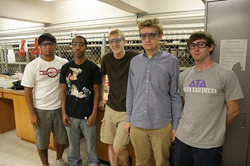
Wiki Page/Report Compilation: Pace Nalbone
References
U.S. Census Bureau (http://www.census.gov/#)
http://michaelbluejay.com/electricity/cost.html
- Price of electricity information (2002 dollars)
http://hypertextbook.com/facts/2004/JosephSabatelle.shtml
- Price of water (2002 gallons)
