Lawnmower carrier
From DDL Wiki
Contents |
Overview
The purpose of this project was to select a product and determine an innovative way to improve it. Our product is a self-propelled lawnmower. We did some market research, which included speaking to people at a lawnmower repair shop. We saw early on that people had a problem transporting their mowers, and we determined that we were going to design a mechanism that makes it easier to move a mower between locations. The design that we came up with was a mechanical lift that slides into a standard trailer hitch. Through the design process, we built multiple prototypes, each time improving our design until we decided on the design for our final prototype. After constructing our final prototype and doing user testing we were able to determine changes that we would make for future designs. We also saw that our product could be used to transport not only lawnmowers but also personal electric scooters, bicycles, and a variety of other things. In the end we were able to create a product that would sell for more than half the price of our competitors and attack a wider market than we had originally expected. This is good evidence that there is a need for this product and we believe, if produced on a large scale, it would sell.
Market Analysis
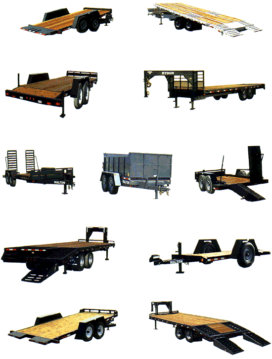
When first examining and dissecting our product, we intended on modifying the lawn mower in a way that would improve its usability, functionality, or performance. We wanted to improve the actual product so that it could better serve the user. Our potential ideas for improvement included a remodeled and ameliorated suspension system to allow for a more even lawn cut, or perhaps a blade speedometer to warn the user if the blades were dropping below an indicated stall-out speed. However, after performing market research and analysis, we realized that it would be difficult to improve upon a product that countless designers had spent time inventing. We spoke with some local retailers, service repairmen, and even our group member Alex, who had cut lawns independently for eleven years. We determined that one of the most significant issues with the lawn mower wasn't necessarily the mowing, rather the transportation of the mower itself. Several people that we spoke with commented on how dirty, labor-intensive, and time-consuming this process could be, especially if the user did not have an appropriate vehicle for transportation. Therefore, we chose to explore the market of trailer hitch attachments that could serve to transit a lawn mower. After examining the market for trailers and the sort, we realized that there wasn't really a product that was convenient for the independent lawn-mowing businessman. One can see from the photo below that the majority of the trailers are much too cumbersome and expensive for a non-commercial entrepreneur.
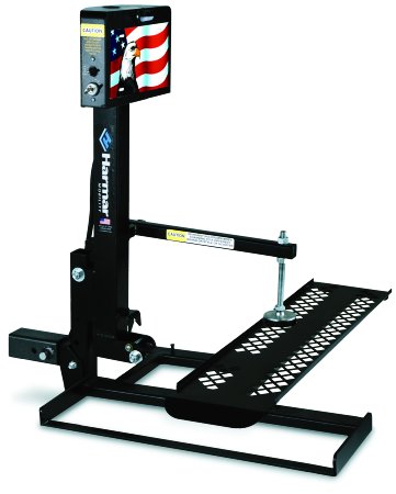
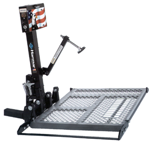
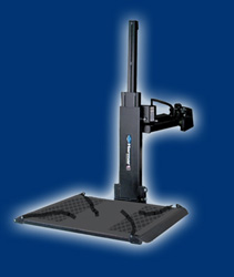
The trailers above range anywhere from $1,000-$5,000 in price and several of them are not appropriate for your average vehicle. We also researched the prices and designs of mobility scooter lifts for more comparison. A variety of this type of lift can be seen in the images below:
The scooter lifts were very similar to the idea we had in mind for our lawn mower carrier lift, yet they were still more expensive than what we predicted. These lifts usually cost anywhere from $1,000-$3,000, which is a significant amount more than our desired market price for the lawn mower lift. Our goal was to create a product that could be easily assembled onto a vehicle, and then easily removed as well. From this research and analysis, we determined that we could create a product that incorporated designs from both of the aforementioned compared products, but one that would cater to both commercial and independent business-owners. After constructing the prototype of the lawn mower carrier lift, we concluded that the cost of manufacture was right at the budget of $500. In order to determine the profitability of this product, one must analyze the methods of production. We could choose to mass produce the lift or produce it on a smaller scale that would entail custom ordering. Mass production would result in a much lower materials and parts cost because ordering them on a large scale significantly decreases their cost. The manufacturing methods for mass production, including stamping, robotic welding, and injection molding, are much cheaper because there is more automation and minimal human labor is required. Using this type of production and considering material costs and the manufacturing costs, the estimated cost of our product is around $250. This would result in a great level of profitability, because the market shows that we could sell the lift for at least $500. Small-scale production would result in less profit because it would much more expensive to produce the product due to an increase in the material and manufacturing costs. If this were the case, the market would allow us to sell our product close to $600, but production cost would approach this, resulting in smaller profitability. Therefore, mass production is the optimal method of production for our design.
Design Documentation
Bill of Materials
Construction
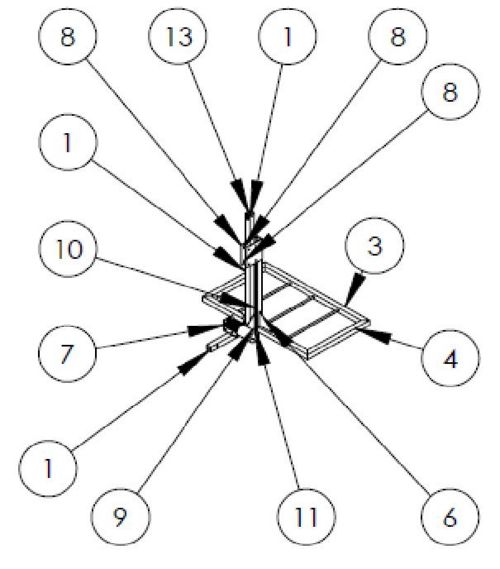
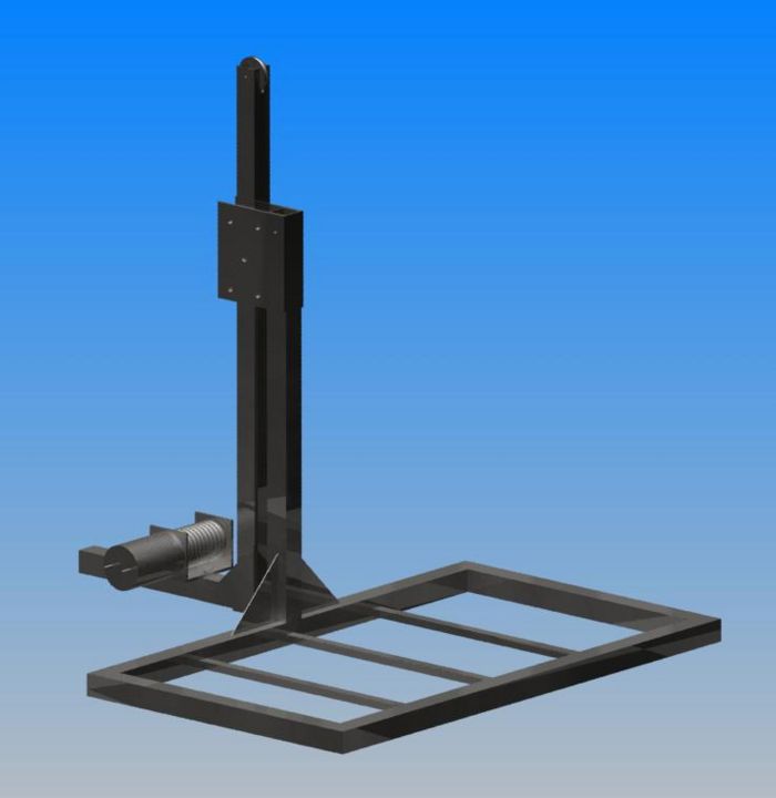
The parts in the bill of materials above are pointed out on the assembly below.
Most of the steps in assembly of the lifting carrier do not matter in which order they are completed, but it may help to follow the pictures in order below.
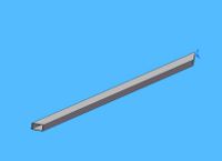
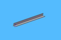
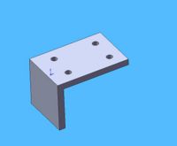
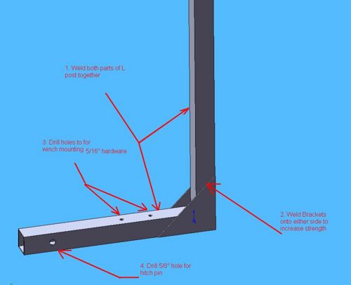
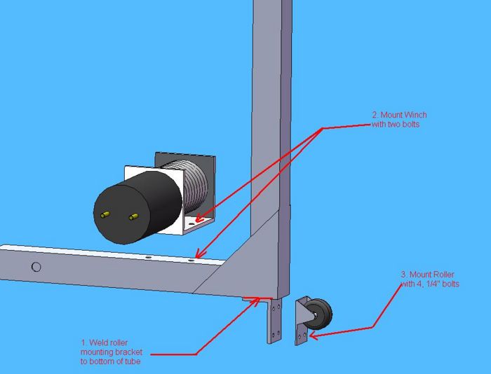
In the first step you want to begin by welding the upright tube and the hitch tube together to form an "L". After that you want to weld the support brackets onto the side of the newly formed "L" as shown below. After that it is a good idea to drill you 5/8" hole 3" in from the end to allow a spot for the trailer pin to slide through. Then drill the two 5/16" holes for the mounting of your winch.
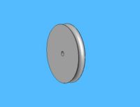
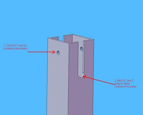
The next step is to move to the upper part of the upright tube. On the end of this you want to drill a 3/8" hole 1.5" down from the top to provide a spot to mount your pulley. You want to make sure the hole is oriented parallel the bumper of the car when it is inserted. Then on the adjacent sides you want to mill a 1/2" slot 2" deep to allow for clearance for the pulley. You want to hold off on mounting the pulley right away because you still need to slide your rollers on the tube before the pulley can be put into place.
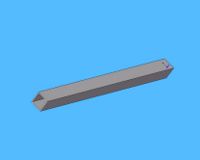
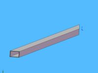
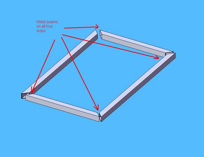
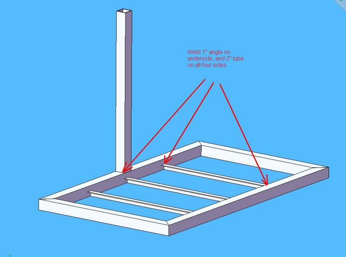
Now you can move onto construction of the platform. To begin you should align and weld the 4 platform tubes together. It is important to rotate the platform and weld on all four sides of the tube to ensure sealing of the tube. If gaps are left in the welds there will be places for water to enter and corrode the steel.
After welding the platform you can weld the upright tube to the centered top of the long platform tube. It is once again important to weld all four sides for strength and sealing. After that is complete it is time to weld the 3 1" angle cross supports into places. Ensure that bottom is flush with the bottom of the platform tube. This allows for part of the tube to protrude from sides of the expanded metal. It will make a nice platform that things will not roll off of. You can also add steel support brackets like you added in the first assembly picture.
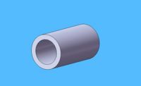
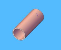
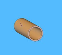
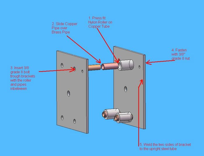
Now you're ready to assemble the roller bracket and rollers. You begin this by press fitting the nylon rollers onto the copper sleeve. Then you insert the copper sleeve around the brass spacer. After this you run your 3" long hardware through the first bracket, then through the brass spacer, and finally the second bracket. You repeat this for all four rollers. (See picture below). After that is complete you can weld the bracket to the upright platform tube at the location pointed out below. Finally for this step you can drill a hole for 5/16" hardware in line with the top rollers. This hole is where you can run hardware to attach the winch cable.
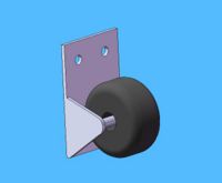
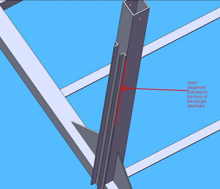
The wheel alignment brackets can now be welded into place. You should place a 1" spacer in between the brackets when welding to maintain a consistent channel for the wheel to slide in.
Finally before you can slide the roller bracket and platform onto the upright tube you should drill holes to mount the winch on the hitch tube. These holes should be 5/16" to accommodate the appropriate hardware. Now is also a good time to weld the roller bracket to the bottom of the "L" shaped tube. You can find the approprates spacing by mocking up the position of the platform upright tube. You should lean on the side of mounting the bracket closer to the vehicle side since washers can always be added.
Now you can slide the rollers down the upright tube and snap your winch cable onto the bolt we inserted earlier. You can also drill holes for the ratcheting straps and the eye bolts. Following this you can install those pieces. You then can attach the pulley and pulley spacers to the top of the "L" tube. After this is all complete you should check all of the nuts and bolts to make sure they are tightened into place. You should also check the integrity of all of your welded connections. Now you are ready to insert the hitch tube into the hitch assembly of your vehicle and begin transporting lawn mowers. Your final assembly should look like the model below.
Final Assembly
Design Analysis
Design for Manufacture (DFM)
The entire system consists of the same material and may be constructed from one single 2 by 2 inch filleted square tube of steel. The vertical support and Lift both are held intact with welds, reducing the number of pins, bolts, screws and nuts needed. This decision increases the difficulty of building the product by incorporating a method that is highly demanding in skill level and cannot be performed by someone without formal training. If we were to mass produce our product, the vertical support and anchor would be one 2 by 2 inch filleted square tube of steel bent to fit the specifications of our final prototype, increasing strength in the joint area and cutting down the cost and time of welding the two sections together. Another change would be to have the lift connection to the vertical lift be folded tabs from the lift to reduce time and costs of having a machinist mill down the tabs to fit around the vertical support with a close clearance. We would also modify the lift gate base to consist of 1 bent bar welded to the perimeter of the base design and welded to the vertical lift connecting arm. The base grate would be stamped out in the direction that increases its rigidity. Depending on the scale of production, we’d opt for a parallel conveyor setup to produce each section of the lift simultaneously and have the final welds applied at the end of the line when the lift and vertical support were bent to their proper shapes.
Design for Assembly (DFA)
The assembly of the product is more than likely to be a by hand assembly with machine assistance. The components are heavy and would be difficult for one person to assemble the whole product. The Lift is more than likely going to be a customized order product rather than a mass-produced product. The product requires plenty of welding as noted in Design for manufacture. The overall assembly would consist of inserting all the rollers and pulleys into the vertical support, attaching the pulley on top of the vertical support, stability wheel onto the base off the vertical support, wiring the winch’s tensile cable from the Lift anchor through the vertical support pulley, inserting the lift safety locking pin and anchoring the winch to the hitch connection. There would actually be very few fastening parts in total due the welds we’ve incorporated in holding the system together. The actual installation of the product onto the vehicle hitch is an assembly that can be left to the consumer, or may be done by a set of staff members to load the lift into the hitch and place the hitch pin into the hitch to lock the lift in place. If on the other hand we were to mass produce the lift. Assembly of the rollers and pins would be left to a small staff of roughly 30 to complete the installations of the final screws, rollers and the winch.
Failure Mode Evaluation Analysis (FMEA)
| Item | Function | Failure Mode | Effects of Failure | S | Causes of Failure | O | Design Controls | D | RPN | Recommended Actions | Responsibility and Deadline |
|---|---|---|---|---|---|---|---|---|---|---|---|
| Support Pin | Lock lift in up position | Shear | Lift may fall | 7 | Overload | 2 | Thicker diameter | 2 | 28 | Increase hole size on lift and vertical support and pin | Design team (complete) |
| Grate Base | Hold mower/ Load | Corrode/ overload | Load will fall | 8 | Overload | 2 | Primer and Paint | 8 | 128 | Aside from painting, throw another support along the middle | Design/ welder Pre-production |
| Winch Cable | Connect Winch to Lift | Snap | Lift falls, bodily harm | 9 | Over load/ wear | 2 | Increase thickness | 2 | 36 | Look find appropriate cable to support a factor of safety of 4 | Design team (complete) |
| Top Pulley | Direct Winch Cable | Crack | Cable can’t move | 7 | Over loading / elements | 3 | Protective UV coating to prevent sun baking | 2 | 42 | Find resistant material that wont seize with metal cable | Design team (complete) |
| Bottom Pulley | Direct Lift and prevent instability | Crack | Lift rocks when active | 3 | Pressure from lift | 2 | Choose sturdy material for pulley | 5 | 30 | Increase number of pulleys to spread the load | Design team (To be included in Final product) |
| Welds | Hold Lift components/ Hold Vertical support components | Crack Bad fusion Metallurgy failure | System falls apart | 10 | Faulty welds | 1 | Joint Design | 6 | 60 | Research weather proof winches | Manufacture team (completed) |
| Lift Platform | Hold Grate base/ Load | Collision | Grate & base loses form | 5 | Impact | 5 | design hitch lock pin to fail before it deforms | 1 | 25 | Design hitch pin with smaller diameter to save gate frame in case of collision | Design team (To be included in Final product) |
| Lift | Raises mower/Load | Rail locks w/ guide pulley | Loss of function | 3 | Hill grade too great | 6 | Make rail slightly wider than wheel | 4 | 72 | Widen Rail | Design team (implemented for final Design) |
| Winch Electrical Components | Control motor to do work | Servo doesn’t respond to commands | Loss of function | 3 | Overexposure to rain and or snow | 2 | Use a weather proof winch | 5 | 30 | Research weather proof winches | Design team (complete) |
| Base Anchor | Hold system onto vehicle | Fracture | System collapse | 10 | Overload on to lift | 2 | Weld design | 4 | 80 | Perform safety analysis and increase factor of safety | Analysis team (completed) |
| Rollers | Guide Lift | Seizing | Lift sticks to rollers | 4 | Temperature / Pressure | 7 | Provide spacers to prevent locking against roller brackets | 3 | 84 | Tread the rollers | Design team (To be included in Final product) |
In this FMEA Chart, severity was rated on a scale of 1-10 where 1 was no danger, 5’s were failure that that disabled the lifts use, 10’s were failure that disabled use beyond repair and may cause bodily harm to user/ passerby. Occurrence was rated on a scale from 1-10 where 1 was highly unlikely, 5’s were moderate/ occasional failures, and 10’s were inevitable guaranteed failure. Detection was rated on a scale from 1-10 where 1 was a failure that could be easily seen, 5’s were failures that could be detected with a light physical inspection and 10’s were failures that required removal of a sub assembly to inspect.
The highest severity came from Welds failing, the base anchor breaking, and the winch cable snapping. The weld failing is something we feel is of little concern but to ensure that this does not occur we plan to have the welds done properly by machine in the case of mass production and by a skilled welder in the case of customized production. The base anchor breaking is another failure with a high severity but is highly unlikely unless the lift were grossly over loaded or inserted improperly into the vehicle hitch. The last highest severity came from the winch cable snapping. This failure was unlikely but due to the severity and the fact that the winch cable snapping might hurt the user lifting his/her object, we felt we’d look into it to avoid harming a customer/user. We did stress testing on the winch cable and found that it would hold 400 Lbs. in tension safely with a factor of safety of 4. The easiest way to prevent the cable from snapping is to choose a winch motor that would not be able to lift the 2000 lbs so that the lift would cease to function before the cable could snap and cause serious danger to users. Another safety measure was to install a pin to take the load off the cable while the vehicle was in motion and prevent the tension in the cable to rise to an unsafe level after the vehicle runs over a pot-hole/ speed bump.
Design For the Environment
For the most part, our impact on the environment would not change significantly with respect to our initial estimates using EIO-LCA. Our lift can be used to lift more than just mowers, after realizing we could lift 400lbs we opened our eyes to the possibility of using the lift to transport power scooters for the elderly/ physically impaired. Once the winch motor expires, the lift can be used strictly as additional cargo space to transport luggage or miscellaneous items that fit on the base and can be secured with the supplied ratchet straps or even bungee cords. Post need of extra cargo space, the entire product may be melted down and re-used for other steel applications. We intend to coat the product with a primer that would leave the steel uncontaminated and prevent corrosion from the elements. By doing this, when it was time to recycle the product, it will be ready to melt down after being sanded down to the steel. For the most part, we would consider product to be similar in nature to our initial set design with respect to the components the lift gate requires minus the use of a fossil fuel as a direct power source. For data on the Environmental impact see DFE of initial report.
[[1]]
House of Quality
Quality Function Deployment (QFD) was employed to benchmark our product against existing competitors in today's market. This process allows us to gain a deeper understanding of the benefits/disadvantages of our product within the marketplace and the relationship between the customer's requirements and quality characteristics of the lift. We chose to compare our product to a general utility trailer and mobility scooter lift in the House of Quality (HOQ) below:
| Error creating thumbnail: convert: unable to open image `/ux0/websites/wiki.ece.cmu.edu/wiki/virtual-hosts/ddl/images/House_of_Quality.jpg': No such file or directory @ error/blob.c/OpenBlob/2882. convert: no images defined `/ux0/websites/wiki.ece.cmu.edu/wiki/virtual-hosts/ddl/images/thumb/House_of_Quality.jpg/500px-House_of_Quality.jpg' @ error/convert.c/ConvertImageCommand/3235. |
Through the application of this process along with this diagram, we can obtain several conclusions about the success of our product in the market as compared to the others. This process also highlighted strong and weak relationships between the quality characteristics of the lawn mower lift, allowing us to greatly improve upon our design. Our product does not surpass the bench marked products in many of the assessed categories, but it exceeds in very important customer requirements: low cost, minimal weight, ease of assembly, and usability. We believe that the values our product received in the aforementioned categories constitute a marketable and dependable product.
Mechanical Analysis
Since our prototype is made mainly of steel it is important to analyze the forces in key components to ensure safety. The purpose of this analysis will be to show the reaction forces in the rollers when the lift is in the elevated position. To perform this analysis we will have to make several assumptions. First, we will assume that there is no tension in the cable and that all the weight is on the pin. This is the worst case scenario as ideally the cable should be supporting the weight during transport. We will assume the weight of the mower to 200 lbs (almost twice its actual weight). Another assumption is that the rollers fit snugly to the upright and therefore there are no reaction forces on the pin in the horizontal direction. It is also assumed that the reaction forces in rollers 4 and 5 are zero.
The following diagram shows the mower lift and the distance values to be used in the analysis (COM stands for center of mass of the mower, lifting platform and bracket containing rollers).
| Error creating thumbnail: convert: unable to open image `/ux0/websites/wiki.ece.cmu.edu/wiki/virtual-hosts/ddl/images/Free_Body_Diagram.jpg': No such file or directory @ error/blob.c/OpenBlob/2882. convert: no images defined `/ux0/websites/wiki.ece.cmu.edu/wiki/virtual-hosts/ddl/images/thumb/Free_Body_Diagram.jpg/500px-Free_Body_Diagram.jpg' @ error/convert.c/ConvertImageCommand/3235. |
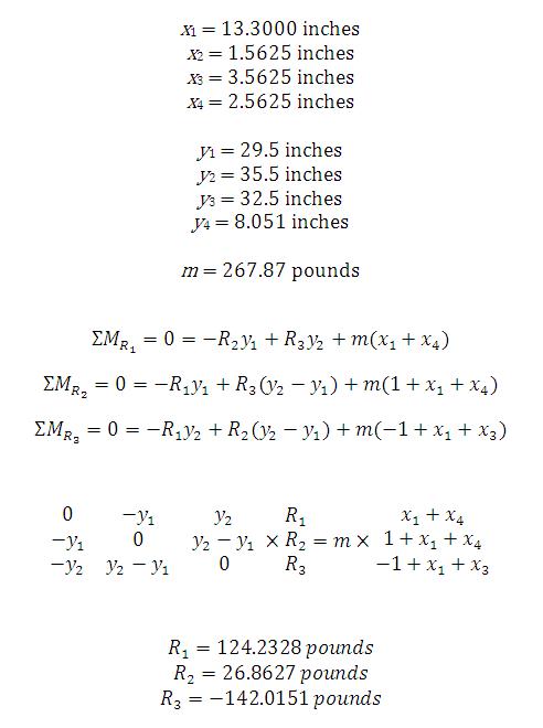
Assuming static equilibrium, the values of the lengths and weights and the equations of motion are as follows:
Using matrix algebra we are able to solve for the three reaction forces. The values are as anticipated and can be interpreted as follows: the reaction force at roller 1 is 124 lbs to the right, the reaction force at roller 2 is 27 lbs to the right, and the reaction force at roller 3 is 142 lbs to the left. While these values do not add to zero as they should in static equilibrium, there is only a minor discrepancy. This can be accredited to approximation of the weight and center of mass of the mower on the platform.
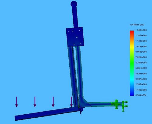
To supplement this analysis we performed a COSMOSWorks analysis on the lift. The model is restrained at the point where it slides into the hitch. A 200 pound force is applied to the platform to simulate the mower (this value is exaggerated to simulate the worst case scenario). This model also assumes that all of the weight is placed on the pin that goes through the roller brackets (again, a worst case scenario assumption). The following plot shows the stress throughout the system. From this we can see that the maximum stress the system will see is in the steel tubing and is around 4000 psi. The yield strength of carbon steel is around 65,000 psi. This yields a factor of safety of around 16 which is well within accepted safety standards.
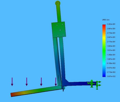
The following plot shows the displacement of the system under the same loading conditions as previously mentioned. From this plot we can see that the maximum deflection, which takes place on the far end of the lifting platform, is about 0.3 inches. This is an acceptable deflection value for exaggerated loading conditions.
Prototype Documentation
Throughout the design process, we constructed three prototypes to physically analyze our design and improve upon it. These prototypes were essential to obtaining a high-quality, functional final design and product.
Prototype I
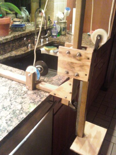
The blueprint of our first prototype was surprisingly similar to that of our final prototype. It was constructed primarily out of wood, and was intended to demonstrate the lifting method of our product. The prototype consisted of a platform, pulley system, hand crank (to simulate a winch), and a clamping piece. We noticed with this prototype that it was quite difficult to actually lift the platform, which gave us ideas for improvement upon the pulley system and material choices.
Prototype II
Our second prototype was constructed using the base of Prototype I, but we incorporated the new pulley system that we had designed since our first prototype. This prototype was intended to demonstrate the ease of lifting with the application of this new pulley system. As opposed to having a pulley located on the winch-side of the device and lifting it from this side, we chose to place a pulley at the top of the device and lift the mower from the platform-side of the device. We also incorporated some new material choices, including the delrin rollers, which resulted in a smoother lifting of the platform. An image of the prototype is presented below:
Final Prototype
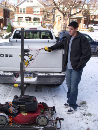
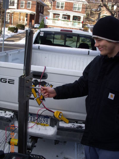
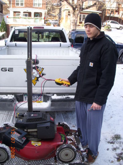
For our final prototype, we integrated all of our final material choices, the revised pulley system, an electric winch, the support L-brackets, and the rolled steel grating for the platform. The construction of this prototype involved MIG welding, drilling, bolt cutting, and several other processes to ensure its functionality. We used 2" carbon steel tubing (to comply with standard trailer hitch sizes) for the majority of the device, delrin rollers and brass spacers within the roller bracket assembly, 1/8" steel plating for the support brackets, and a Chicago Electric Winch with a steel cable rated at 2000lbs of force. The winch attaches to a standard 12V car battery and has bidirectional pull power for the raising and lowering of the platform with the mower on it. We also affixed ratcheting tie down straps on the platform to secure the mower or whatever object needs transporting. We were nervous to test this prototype because of the various mechanisms involved, but it worked on the first try and seems to be a reliable device. An image of our final prototype is displayed below:
Production Differences
There are a few notable differences between our final prototype and the product we would like to introduce to the market. After performing driving tests with our product attached to the trailer hitch of a Dodge Ram, we noticed that the main issue with the device was that there was lateral instability of the platform. Going over bumps caused the platform to wobble side to side and it was decided that a necessary step for production would be to add more tie-down straps from two of the outer corners of the platform to the top of the device. This step would provide the additional stability needed, resulting in a product that it is safe for driving under extreme conditions. It became apparent that our prototype did not reach a safe lifting height, which might cause bottoming out on steep hills and such. Our solution to this problem is the addition of another roller located above the original roller to provide a few more inches to the lifting height. This design presents another problem, however. If the platform is raised too high, bending could occur in the upright steel tubing. Therefore, the final product would require a sensor switch located on the upright steel tubing to turn the winch off when it would cause bending. We also realized after cutting the steel mesh grating for the platform that it's stronger in the opposite direction, so we would reorient the grating for the market product. Finally, we realized that the steel tubing connecting into the hitch wasn't long enough for a full opening of a truck bed door. This can be vexing if the consumer would like to place other items into the bed of his/her truck, so it is essential to add a few inches of elongation to this part of our device. With these changes, we are confident that there will be a great demand for our product in the appropriate marketplace.
