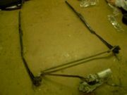
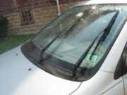
Removable windshield scraper blade
From DDL Wiki
Contents |
Executive Summary
The following document contains a report on a new product design. The purpose of this report is to analyze a windshield wiper system and come up with an improvement to this product. More specifically, we purchased the windshield wiper system of a ’96 Corsica and designed our product around that model. Windshield wipers are mainly used by customers for removing precipitation from the windshield so as to increase driving visibility and safety. Due to the fact that the primary purpose of this product is safety, it is important for the product to be reliable and functional. Ease of use is also a high priority because of quick-think situations that customers may find themselves in. Lesser in importance are maintainability and cost.
In the initial stages of our analysis we took apart our product to examine the way it works, get a part count, look closely at the DFMA aspects of it, and determine what could be improved. Based on the analysis of the DFMA of the current product, it seems to have already gone through a DFMA process. One area of improvement would be to standardize the parts, as most of them are unique.
After analysis we had a better understanding of how our product worked mechanically and how it was put together. We next did some brainstorming along with market research to come up with areas that the product could be improved or places where a new product could be made. Based on the market research we found that people were most concerned with leaves getting stuck under the wipers, the blades being ineffective in the winter, the disposal system of the blades not being environmentally friendly, and the blades not lasting long enough. Per these top concerns we came up with the four best designs out of all of our ideas.
The first idea is heated blades, in which the blades of the wipers would be heated for easier snow and ice removal. The second is easily removable blades, in which the rubber part of the blade is made to snap into the wiper so that exchanging them is easier and more environmentally friendly. The third is a compressed air system that would eliminate blades all together and would be very good at removing leaves and other loose debris from the windshield. The final is a multiple-blade system that would incorporate both a rubber wiper for rain and a hard plastic scraper for removing snow and ice. After doing some analysis of each we decided to go with the multiple-blade design.
The final product is a detachable scraper mechanism. The idea behind it is that when you go out to your car in the morning or after its been sitting outside for a while and there is snow or ice on it you can simply grab these detachable scrapers from your car. The scrapers attach to mounts on your windshield wipers with an easy push and twist motion. Then you turn your wipers on and either sit in your car or wipe the rest of your windows while the scraper devices are working on your windshield. These devices would be stored in your car while not in use, much like current scrapers. In conjunction with the wiping we would recommend that the defroster be turned on high while the scrapers are wiping so that the bottom layer of ice will become looser.
Our recommendation is that this product not be put into production yet. Due to the time of year the product was designed in, sufficient testing was could not be conducted to ensure functionality in icy conditions, although previous tests and intuition strongly lead us to believe that the product would perform well in such tests. Our advice would be to test this prototype more extensively in the coming winter months. Using the test results a final design iteration should be made. At this point we feel the product would be ready to be put into production.
Background
We chose windshield wipers as our product to disect and improve. To begin with we took the windshield wiper system off of a '96 Corsica to analyze. First we examined the product usage. Windshield wipers must be manually activated. Thus, the first step in the wiper usage process is that the user must decide that he or she wants to activate the wipers.
This decision is typically made for one of two reasons:
- The driver decides that the windshield is dirty and wants to wash/clean the windshield.
- The driver's visibility is blocked and wants to remove material from on top of the windshield. Situations such as these typically include:
- Raining
- Snowing
- Hailing
- Excessive leaves/flowers on windshield
Once the vehicle driver decides that they would like the windshield wipers to clean the windshield, he or she must shift a lever, typically behind the steering wheel and to the right. The controls are designed so that the driver can feel for the control stick and shift the wipers on without needing to take their eyes off of the road.
We next dissected the product to determine how it works and the components in it. A table of all the parts can be found here. We observed that the assembly seemed to have gone through a DFX process already. We still found a few areas for improvement such as making more of the parts identical and making the steel manufacturing process less harmful to the environment. We were also able to assess the greatest areas of potential failure after our dissection. Based on traditional FMEA the greatest risk of failure is in the hose, followed by the thermal mount. A scenario-based FMEA was done on the hose and thermal mount and the expected cost of the thermal mount greatly exceeded the cost of a failure in the hose. Thus, it is actually more important that the thermal mount be well designed than the hose, even though the hose has a higher expected failure. The recommended action for the hose would be to increase the wall thickness. The recommended action for the thermal mount is the safe-guard the rubber against corrosion.
We also did some testing of windshield wipers on a Toyota Corolla. From this testing we gained more insight into the problems involved with windshield wipers, such as leaves getting stuck in the blades.Our next steps involved doing market research and coming up with product ideas. A list of our product ideas and interviews with product users can be found here. From the interviews, the problems we wanted to address were poor winter performance, difficulty in changing the wiper blade, and the desire for a more environmental solution. From research we saw that lack of proper maintenance was an extremely common problem. So we focused on ways to improve the user’s experience in the winter, and on ways to encourage the user to change their blades more often by making the process easier and/or more environmentally sound in our product ideas.
After coming up with nearly 100 product ideas, we narrowed them down to our top four ideas. The first is heated blades, in which the blades of the wipers would be heated for easier snow and ice removal. The second is easily removable blades, in which the rubber part of the blade is made to snap into the wiper so that exchanging them is easier and more environmentally friendly. The third is a compressed air system that would eliminate blades all together and would be very good at removing leaves and other loose debris from the windshield. The final is a multiple-blade system that would incorporate both a rubber wiper for rain and a hard plastic scraper for removing snow and ice.
We used a Pugh chart to analyze each idea and found that we could easily remove the compressed air system as a possible solution because it ended up with a net score of -4. The highest scoring design was the easily removable blades, with a net score of 8. We decided however, to go with a multiple blade system as our final product because it was a more interesting and innovative solution and it still netted a score of 4. Since heated blades, with a score of 3, and easily removable blades both scored positively and are more minor design problems we decided to look into incorporating one or both with the multiple blade idea.
Market Research
It’s winter. It’s freezing and wet outside; it’s warm and dry in your car. To no one’s surprise, we found that people would like to get ice off their windshields without having to be outside scraping it off. We found that there were no products designed for this purpose. We saw an opportunity to fill a niche that was clearly not being met: Given an effective design, people would buy the product because of a near universal distaste for standing outside in the cold while scraping ice off a windshield.
When determining if the windshield scraper idea that we came up with would be something that people would actually want to buy, we sampled people we knew to get reactions to design ideas. We each contacted five to ten people, and between the four of us, only one person didn’t like the idea. There were, however, several people who had reservations, generally centered around the ease of attaching the unit and how quickly it would get rid of the ice.
When we were trying to decide what kind of attachment we should make between the wipers and our blade, we thought it would be time to do some more market research regarding what most people’s windshield wiper blades look like. What the problem boiled down to was the following question: Did a large enough percentage of people’s wiper blades have holes on top and a recess that we could justify the use of a permanent attachment part that utilized these holes? Our target demographic was individuals with plenty of disposable income and an affinity for gadgets. To get a good cross section of what type of windshield wiper that group had on their cars, we started out in CMU’s parking lot and surveyed the cars. We found rather favorable results; most of the windshield wipers had holes in their wipers. Then we decided to expand our sample to include cars parked in the Pitt University area, and found similar results. In the end, we sampled more than a hundred cars, and found that, when all was tallied up, the result was 1 to 13 in favor of holes in the wipers. One other thing that we noticed that could interfere with the mount was that a few cars had non-identical windshield wipers, one large and one small, but since this was an extremely small group, we decided it was not something to be overly concerned about.
After testing our final prototype on a car, we conducted an interview with the car owner on her thoughts about the product and the test. She felt that the product was efficient at pushing the snow off of the windshield and she was satisfied that the product would not damage her windshield or wiper system in any way. She also commented that the detachable scraper was very light. She felt that this product would be more effective at getting snow and ice off of her windshield than her current wipers, though she noted that the scraper could have a thinner and sharper edge to improve its performance. She noted that the attachment and detachment were completed in under a minute, meeting a customer requirement identified in the QFD. Finally, she felt that the price of $19.99 is fair and even a bit on the low end of what she would be willing to pay.
Design
Please see the assembly drawing for a labeled image of how the parts fit together. Below is a bill of materials summarizing the type and number of parts used in our final product design, as well as the manufacturing process we propose to use to create the parts. The numbers of parts are meant to reflect the materials needed to create a pair of 2 scraper blades.
Bill of Material
| Part | Quantity | Material | Function of Type | Manufacturing Process | Drawing Number or Catalog number |
|---|---|---|---|---|---|
| Blade | 2 | ABS Plastic | To scrape the windshield and push snow off | Injection Molding | 1 |
| Chassis | 2 | ABS Plastic | The base for connecting the blade and attachment to the wiper via knobs (handles) | Injection Molding | 2 |
| Knob | 4 | ABS Plastic | The handle and turning piece used to attach chassis and blade to mount | Injection Molding | 3 |
| Mount | 4 | 6061 Aluminum | The permanent piece that allows for easy attachment | Injection Molding | 4 |
| Tab | 4 | ABS Plastic | This is press fit to the knob; Secures the chassis by fitting into the slot on the mount | Injection Molding | 5 |
| Block | 4 | 6061 Aluminum | This is placed inside the wiper and is used to screw the mount in place on the wiper | Stamping | 6 |
| Spring | 4 | Piano Wire | This is used to provide additional friction between tab and mount by increasing normal force | purchased | C14-035-040 |
| Screws | 12 | Stainless Steal | 6-32 X .25 | purchased | done by quotes |
Links to PDFs of all the drawings for our product:
[Assembly Drawing]
[Blade Drawing]
[Chassis Drawing]
[Knob Drawing]
[Mount Drawing]
[Block Drawing]
[Tab Drawing]
Note on Drawings
The drawings use the common convention that tolerances are determined by the number of places past the decimal point. Most of our product is designed around being able to have very loose tolerances. An example of this is in the chassis. There is more space available for the mounts than there needs to be, so that part does not have to be very precise. There are, however, a few places where the tolerances have to be greater, e.g., as when the holes in the chassis for the insertion of the knob need to be more precise.
Pricing, Material Selection, and Mold design
We plan to make our product out of ABS. ABS is a thermoplastic and lends itself to processes such as injection molding very well. ABS is also a tough material able to handle the types of loads that will be applied to it. A quick roundup of its properties is at the end of this section.
For our model we decided to use Lustran ABS 433 for all parts except for the blade, for which we planned on using Lustran ABS 266. Lustran ABS 433 comes in black high gloss, which should give our design a nice slick look and is one of the low costing forms of ABS. It is also commonly used in injection molding application. ABS 433 is used for automotive applications and other consumer applications. The supply of that we would use is LanXess (there is a PDF in the reference section that has the technical data for using this plastic in injection molding). It is also important to note the environmental impact of Lustran ABS 433; it meets all environmental guidelines for both the US and the EU. LanXess offers documentation to show that it meets several guidelines such as the RoHS-Directive. Lustran ABS 266 is a transparent form of ABS which was felt to be desirable for the blade. Even though this is a different kind of ABS, the shrinkage rates are almost identical so no special tooling or changes would be necessary to accommodate the difference. Lustran ABS 266 is also used for automotive and commercial applications and is only marginally more expensive than the black ABS that we planned on using for the rest of the product. It also meets the same environmental standards as ABS 433.
Properties of ABS Plastic
Tensile Strength
5000-7500 psi
Flexural Modulus
270,000-380,000 psi
Impact Strength
3.0-7.5 ft-lb/in notched izod
Maximum Temp.
200 F short duration, 140 F long term
For the initial production run, we will start out with a cheaper, quicker-to-make aluminum mold until the design is perfected so that changes can be easily made. Aluminum molds cost much less than steel molds, and we will be able to make them quickly with a CNC; in this way we can go through a few generations before a steel mold is constructed. The most complex part is the chassis, and it is not all that complex, so the molds and process should be very low cost. Assuming that we have a total first run of 500,000, and factoring that our aluminum molds will have to be replaced a couple of times in the process, the costs per part are in the table below. These numbers are based on cost estimator software provided by David O. Kazmer, P.E., Ph.D. from the University of Massachusetts Lowell. The two aluminum parts, the mount and the block, are created in two different ways: the mount is injection molded (similarly to other parts of the model), and the block is stamped. The cost of the injection-molded mount was figured using the cost estimator software but including a recommended correction factor for the use of a metal verses ABS, the cost of which was factored in on the “cost of materials” section. The cost of the stamped block was figured based on rates for the cheaper process of stamping but with a higher material cost of aluminum verses ABS.
| in $ | Process Cost | Material Cost | Tooling Cost | # of Cavities | Quantity | Total Cost |
|---|---|---|---|---|---|---|
| Blade | 0.3 | 0.06 | 0.07 | 1 | 2 | 0.88 |
| Chassis | 0.07 | 0.04 | 0.02 | 4 | 2 | 0.24 |
| Knob | 0.58 | 0.07 | 0.01 | 2 | 4 | 2.64 |
| Tab | 0.27 | 0.001 | 0.02 | 1 | 4 | 1.16 |
| Mount | 0.15 | 0.25 | 0.02 | 2 | 4 | 1.68 |
| Block | 0.01 | 0.09 | 0.02 | n/a | 4 | .48 |
Which gives a total cost for Manufacturing the parts of: $7.08
The number of cavities for our mold is in the table as well, because cavities have a great impact on the cost of the process. It is much more economical to have more cavities on medium and small parts, as in our design, than on larger parts. Some of the parts did not seem as though they could have the extra cavities, but the chassis has places for at least four and the knob for at least two. On larger parts it is more economical to have only one cavity, which is why the blade has only one cavity. The blade, chassis, mount, and tab all have thin walls, which is a very important design characteristic when it comes to injection molding. The wall thickness often dictates variables such as flow length and injection pressure; if the walls are too thick it may lead to long cycle times and defects. While the knob is a thick part and will have longer cycle times (which was factored in on cost), it shouldn’t have too many problems with defects because it is a very simple part.
Purchased Items
The parts that we intend to buy are the springs and the screws. The supplier for the springs is W.B. Jones Spring Company, Inc. (see link in Reference), which has a spring that almost exactly meets the requirements determined by our analysis. The only issue is that the spring has almost double the number of coils that we require, but they do take custom orders. The plan is to buy the stock springs and cut them in half until our custom springs are ready. By picking a spring that is already in stock, we should be able to get the changes we need to these without that much extra cost and in a relatively quick time frame. The screws should not cost that much either. We can buy them from a large manufacturer and bulk distributor like American Fastener (see link in Reference). Below is the estimated cost of our purchased parts.
| Cost | Quantity | Total Cost | |
|---|---|---|---|
| Spring | .01 | 4 | 0.04 |
| Screws | 0.005 | 12 | 0.06 |
The total cost for our purchased items is: $0.10
Bringing our total cost up to: $7.18
Assembly and Indirect Costs
Once practiced at assembling the scraper it does not take more than a couple of minutes to construct a set of scraper blades. The Mechanical Process book gave a figure of $35 per hour including overhead for assembly cost. This works out to approximately $1.15 per set of two blades for assembly. This brings the total cost of our product up to $8.33. We plan on allocating $1.75 to marketing and distribution expenses. Using existing wiper, scraper, and car modification products as a benchmark, we decided to sell our product for $19.99. All of this gives us a total profit of $9.91 per set of two scrapers sold.
Analysis
Handle Spring Optimization
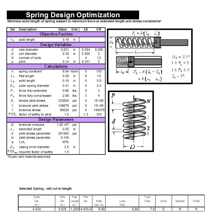
In designing our spring-loaded handles for attachment and detachment of the scraper to the wipers, we realized that analysis would aid in our selection of the springs. Springs with a high spring constant will provide large amounts of normal force between the chassis and the mounting blocks, providing friction so that the handles do not accidentally turn and release the scraper. However, a spring constant that is too high will make it difficult to fully compress the springs and get push the tabs into the mounting pieces. After experimentation with a force scale, we decided that approximately 3 pounds of spring force when fully compressed was optimal. A further design constraint was that the spring had to fit around the outside of the handle. Our goal for the optimization was to minimize the solid height of the spring, because the shorter the spring was when fully compressed, the shorter we would be able to make our handles and the smaller and lighter our part would be. Below is a screenshot of the optimization, done in Excel.
Scraper Blade Curvature Analysis
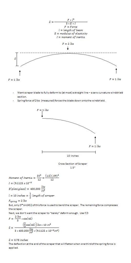
In order to acheive a contouring scraper blade, we pre-bend the scraper blade. When the blade is forced down into the windshield, the curvature is pressed out and the blade fits snuggly onto the windshield and doesn't allow ice and debris to sneak under. A spring in the wiper arm forces the wiper blade down onto the windshield; experimentally we measured this value to be approximately 2 pounds. Thus, we had to design our curvature such that 1) the curvature was enough to contour to the most curvature that we could expect to find in windshields, and 2) the 2 pound spring force, when applied at an angle, was enough to entirely flatten the curvature.
To solve this, we analyzed the statics of the situation and modeled the scraper blade as a deflecting beam. The calculations can be seen below. We decided that we wanted the blade to entirely flatten with just 1/3rd of the spring force, meaning that we didn't want the scraper to "barely" flatten. This resulted in a desired deflection of .78 inches at the end of the scraper. Thus, using a small angle assumption, pre-bending the ends of the scraper to .78" should result in a perfectly flat scraper when 1/3rd of the 2 pound spring force is applied.
DFM
For our product we tried to minimize the number of parts and keep the types of manufacturing processes to a minimum. Because of this we chose to use injection molding for almost all parts. Stamping was used for one part because it was believed that it would not be economical to make such a simple piece out of injection molding. The types of plastics, the types of molds, and the cavity numbers are discussed under the design section. There is also a brief discussion of production volume in the design section, mainly that there would be a first run of 500,000 and once that is complete steel molds would be constructed. From there this would be a mass marketed item hopefully sold in places ranging from Target to Jiffy Lube. The heavy volume that this would entail justifies the use of expensive machinery.
DFM Characteristics
The product uses two kinds of ABS; both have good flow properties, good dimensional stability, are easy to process, and are relatively cheap forms of ABS. We also decided to use forms of ABS that both use a Lustran resin and have near identical processing times. This conformity of properties should help during production and from an engineering standpoint. The similar properties will allow what is learned from molding one part to be applied to other parts.
The stamped part will have to be taped but the other threads needed for our product can be molded.
The thicknesses of the walls for our parts are in keeping with what works best with injection molding.
There are no deep pockets or groves that could cause the part to stick to the mold, or snap when being removed.
DFA
DFA Characteristics
The Chassis is our base component that will be used to locate all other components.
While assembly is being done the chassis will only have to be flipped once.
All of the fasteners are the same type.
The Chassis is not symmetrical in any plane; this will help for to simply recognize the top verses the bottom.
There are no places that will be difficult to access when assembling.
None of the parts are so small that they would be difficult to assemble.
Except for the possible exception of the springs none of the parts will tangle or nest in such a way to make it difficult to take them out of there bins.
The knobs could be placed on sliding rack to have magazines of knobs; this making it very easy to grab.
The blades can be stacked for efficient pick and place.
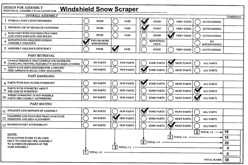
Bellow is a design for assembly assessment worksheet which gives a good break down of how our design ranks. While there is no actual meaning to the end number it dose highlight areas for possible improvement. It also shows the areas that our product is well designed for assembly.
Assembly Process
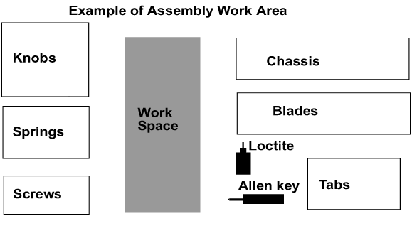
Assembly Steps
Before starting Assemble all materials needed.
1. put chassis in work space
2. take one knob
3. take one spring
4. put spring on knob
5. put knob spring assembly through first large hole in chassis
6. apply loctite to knob
7. screw tab on knob, Note: no tools required tab can be turned by hand
8. repeat for other handle
9. take blade, set down near chassis
10. take screw
11. put screw on allen key
12. put in hole of wiper and align with hole of chassis
13. screw in
14. take another screw
15. screw in at second hole on wiper chassis
16. set finished product in bin to move on to packaging
17. packaging assembly – take two finished blade/chassis sets, four mounts, four blocks, four more screws put in package.
DFE
Production Analysis
The attachable blade will fall under the "Motor Vehicle Parts Manufacturing" sector of the EIO-LCA analysis. Please refer to the table from our Report 1 [1] to see the top contributors of greenhouse gasses and economic values.
Toxic releases are mostly associated with "Copper, nickel, lead, and zinc mining" and "Gold, silver, and other metal ore mining". This indicates that the most harmful step of the life cycle is mining the metals that are used to make the aluminum parts (mounts and blocks). The production and manufacturing of metal components is most responsible for greenhouse gas emissions as well. Transportation of our product is the second most, but due to it's small size, large quantities of our product can be transported at the same time. This requires less transportation overall and decreases the greenhouse gases due to transportation.
When producing ABS plastic it takes approximately the equivalent of 2 kg of oil in raw materials and energy to produce 1 kg of ABS. Compared to the 3.5 kg of oil required to produce aluminum from raw materials, ABS production is not as harmful to the environment.
Product Use
During the product use, there will be a slight increase in environmental impacts. From our testing we have found that adding the attachment requires approximately 1 amp more current from the motor. Thus ,the windshield wiper motor will require 12 Volts*4 Amps = 48 Watts when our product as attached so there will be a slight change in emissions.
End of Life Analysis
During the disassembly process, the mount and block will be recycled because they are made out of 6061 Aluminum. Through a melting and reshaping process the material can be used again either for parts for our product or sold as scrap metal. Our ABS plastic parts include a blade, chassis, two knobs, and two tabs for one product. These parts will have to be thrown away in a landfill because it is not cost effective to recycle or reuse them. It is very cheap to use the same molds to make new parts, even though disposal in a landfill is not the ideal environmental solution. The following documentation for ABS shows a more detailed analysis of its properties.
The End-of-Life Vehicles Guideline is posted here to show that there is cadmium, lead, or hexavalent chromium in the ABS that we are using. [End-of-Life Vehicles Guideline]
RoHS-Directive shows that it is in compliance with EU standards and can be sold there. [RoHs directive]
The CONEG documentation shows that the ABS we intended on using also is under 100ppm for other heavy metals. [CONEG-legislation]
The Montreal Protocol documentation shows that our ABS choice does not use ozone depleting substances.
[Montreal Protocol]
The two springs and the four screws should be recycled. With time threading wears down, and springs loose their elasticity making it impossible for them to be reused in a new wiper assembly.
The disassembly process of our final design is based on recycling, reusing, and disposal via landfill. While it is not environmentally ideal that ABS will be thrown away, there is always a trade-off between economic costs and environmental costs in design. We believe that our proposed design benefits the stake-holders more by being affordable and light weight.
Failure Mode Effects Analysis
FMEA is a technique to identify and correct potential failures in design and manufacture before the parts reach the customer. FMEA analysis of the original windshield wiper assembly can be found on our first design wiki page, but the following analysis is specific to the attachable blade mechanism we designed over the course of the semester. Risk Priority Number (RPN) is Severity x Occurence x Detection and indicates the priority of design risk. According to the values for RPN, a failure occuring in the chassis has the highest risk and the plexiglas blade has the least.
| Item and Function | Failure Mode | Effects of Failure | S | Causes of Failure | O | Design Controls | D | RPN | Recommended Actions | Responsibility |
|---|---|---|---|---|---|---|---|---|---|---|
Chassis
| Deformation with use | Does not fit over existing wiper, does not provide a stable support for blade | 5 | Extreme moment caused by the force on the blade, wear with time, improper storage during summer/spring seasons | 5 | Test highest force that can be applied to the blade without deforming chassis | 4 | 100 | Thicken width of ABS or try a stiffer plastic | Design and Materials Engineer |
Tabs
| Breakage | No longer mounts on wiper | 7 | Improper attachment, extreme moment caused by the force on the blade | 3 | Test highest force that can be applied to the blade without breakage | 3 | 63 | Thicken height of tabs/slots in mount, use stronger material | Design and Materials Engineer |
ABS Blade
| Chipping | Scratches windshield | 6 | Chipping/cracking over time caused by wear and/or misuse during storage | 2 | Test what happens when dropped repeatedly | 5 | 60 | Use different material if testing finds failure majority of time | Materials Engineer |
Slots in Mounts
| Corrosion/Wear | Ineffective mounting of part, instability of blade | 3 | Excessive use, extreme weather conditions such as accumulation of ice | 5 | Test wear and tear on part and low temperature conditions | 5 | 75 | Treat with alumiprep and re-apply alodine | Design and Materials Engineer |
CHASSIS
The most likely cause of damage to the chassis would actually occur when the blade is not in use. One can easily imagine a situation where the user carelessly tosses the chassis into the trunk and other debris falls on the chassis, placing strains in ways that it is not designed to withstand. Improper storage could result in deformation of the ABS or even breaking. The most likely cause of this results for a bending moment, as shown in the picture below. Assuming that the chassis can be treated as a uniform beam for the distance shown by a 3.40" dimension, we can calculate the force required to cause yielding. Our results show that when the chassis is not attached to the wiper, a minimum force of about 3.40 lbs applied at the indicated area will result in cracking the ABS.
- ABS Flexural strength: 9300 psi
When the chassis is rigidly attached to the wiper, a similar analysis is shown a bending moment between the center of the blade attachment and the right handle. The right hand side is analyzed because it will create the greatest moment. The force that the handle puts on the chassis counteracts the upwards force from the blade.
As expected, the force required to cause yielding when the chassis is attached to the blade is less than that required when it is not secured. Additionally, the 2.6 lbs will be counteracted by the springs in the handle causing the wiper to lift off the windshield before yielding occurs in the chassis. Despite this, the chassis recieves the highest RPN value in our analysis because it would be the first thing to break (were something to break) and a cracking in the chassis would be detrimental to the utility of our product.
TABS
The tabs have a failure mode in the case that they break at the point where they align in the mounts. This could happen if the force applied to the blade is very large, causing the handle mechanisms to push upwards and creating two shear stresses on the tabs. The following formulation finds the maximum shear force that can be applied before yielding.
- ABS Flexural strength: 9300 psi
- Cross sectional area of tabs: (.1)in * (.2)in
The handle springs create 3 lbs pushing upwards. This distributles 1.5 lbs to the two contact points of the tabs. Combined with a maximum y force of 3 lbs translated to the chassis by the spring force in the wiper arm, the actual maximum expected shear force on the tabs is 4.5 lbs. It is also important to note that the force on the blade translates to the chassis, and the springs on the handles will absorb most of this force. Thus, the realistic maximum shear force of 4.5 lbs is clearly much less than the yield force, 93 lbs. Based on these results, we do not expect the tabs to fail. The RPN value reflects this, as it is second to lowest in our analysis.
BLADE
ABS is a good material choice for the blade because it is durable, easy to mold, and is resistant to weather conditions. It is better than our previous choice of plexiglas because it is less resistant to chipping or cracking. However, if the blade is misued or dropped on the ground repeatedly, chipping could occur. Results from testing will determine to what extent the blade will chip, but we expect these results to not affect our material choice. Additional testing can be done in extreme weather and temperature conditions, with added weight of debris. For these reasons, our FMEA analysis concludes that the ABS blade has a low Occurrence and high Detection value, and has the lowest RPN value in the rare case of a failure mode.
MOUNTS
While it is unlikely, it is possible that the 6061 aluminum mounts will corrode with time. As previously mentioned, aluminum was chosen in part due to its resistance to corrosion, but our research into previous testing has shown that corrosion can occur if exposed to conditions such as rain, snow, or ice for extended periods of time. Our manufacturing process of applying alodine to the mounts is a preventative measure. If corrosion still occurs, we recommend using alumiprep, a lubricant used to clear corrosion, and then re-applying an alodine coating. Wear on the slots of the mounts can also be caused by improper assembly and rough treatment during disassembly. If this damage is so great that the tabs no longer fit into the slots, new mounts will need to be purchased. This failure mode has the second to highest RPN but we expect the customer to be reposible for proper care of the parts and use after treatments previously mentioned at the first sign of corrosion.
Testing
Our product's main two functions are to remove ice and snow from the windshield of a car. Testing in these conditions proved difficult because we had to wait for snow to test outdoors, and we only had mild icy conditions the entire semester. We realized these obstacles early on in our design process and attempted to create an indoor ice test that would prove the feasibility of our design. The first test we created included a cooking pan filled with water and kept in a freezer overnight to create ice. However, we found that the ice created by simply freezing water has very different properties than ice created from freezing conditions outdoors. The ice in our cooking pan had the consistency of ice at an ice skating rink, rather than the large crystallized structure of ice that accumulates on a windshield. Despite this, we were able to conclude that once the bond between ice and the contact surface begins to melt, a layer of water is formed and the ice is easily removed by the scraper. This finding was encouraging because we expect the consumer to defrost the windshield before and during use of the attachable blade. This will speed in the formation of the water boundary layer between the ice and the windshield, causing the force required to remove the ice to lessen significantly.
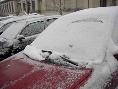
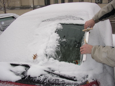
After the first snowfall of the season, we were able to test our prototype on an actual windshield. The before and after pictures shown above shows that the Plexiglas blade does not scratch the windshield when a large amount of force is applied, and clears away the snow and ice in one back and forth motion. This affirmation told us that Plexiglas is a safe choice for the blade and that our final design would be safe to mount on a windshield wiper and run with the wiper motor. This test was also important because it was our only opportunity to test the blade in ice conditions on a car. There was a thin layer of ice beneath the snow accumulated on the windshield and, as is visible in the pictures, the ice was removed with one wipe of the blade. Although we were not able to attach our blade to the wipers during these weather conditions, the test gave us a very good qualitative analysis of the force required to remove ice and the feasibility of our product working in icy conditions. The approximative applied force was 4 lbs, as estimated by the scraping group member. We made sure to place the blade at the same angle that it would have been, had it been attached to the wiper. This result is promising since the motor and four-bar linkage that runs the wipers from our '96 Corsicca was able to lift over 6 pounds of weight.
Although weather conditions did not allow for us to perform extended testing in icy conditions that would best test the capabilities of our scrapers, we did find a willing car owner that allowed us to install our final prototype on their car (see video: [2]). Once installed, we piled snow onto the windshield, and ran the wipers. This test allowed us to confirm many important facts about our design:
- The permanently installed mounting blocks did not obstruct driver vision.
- It is possible to mount our design to multiple types of windshield wipers, so long as they have holes.
- The scraper blade adequately contoured to the curvature of the windshield.
- It was safe for both the wipers and the windshield to install and operate our scraper.
- The scraper effectively removed snow and moisture in one swipe.
- It was possible to attach and detach the removable portion of the scraper from the mounting blocks on an actual windshield.
The results from this test show that our product is feasible. Further testing will be required to test performance in icy conditions. The group believes that the scraper will show a significant advantage at clearing the windshield over unmodified scraper blades.
From this test, we decided to make a few final changes to our final prototype. The angle at which the blade was attached was sharpened to obtain more solid contact with the windshield, and the amount of curvature that we heated into the blade was reduced so that the blade was more pliable.
QFD
Customer Requirements
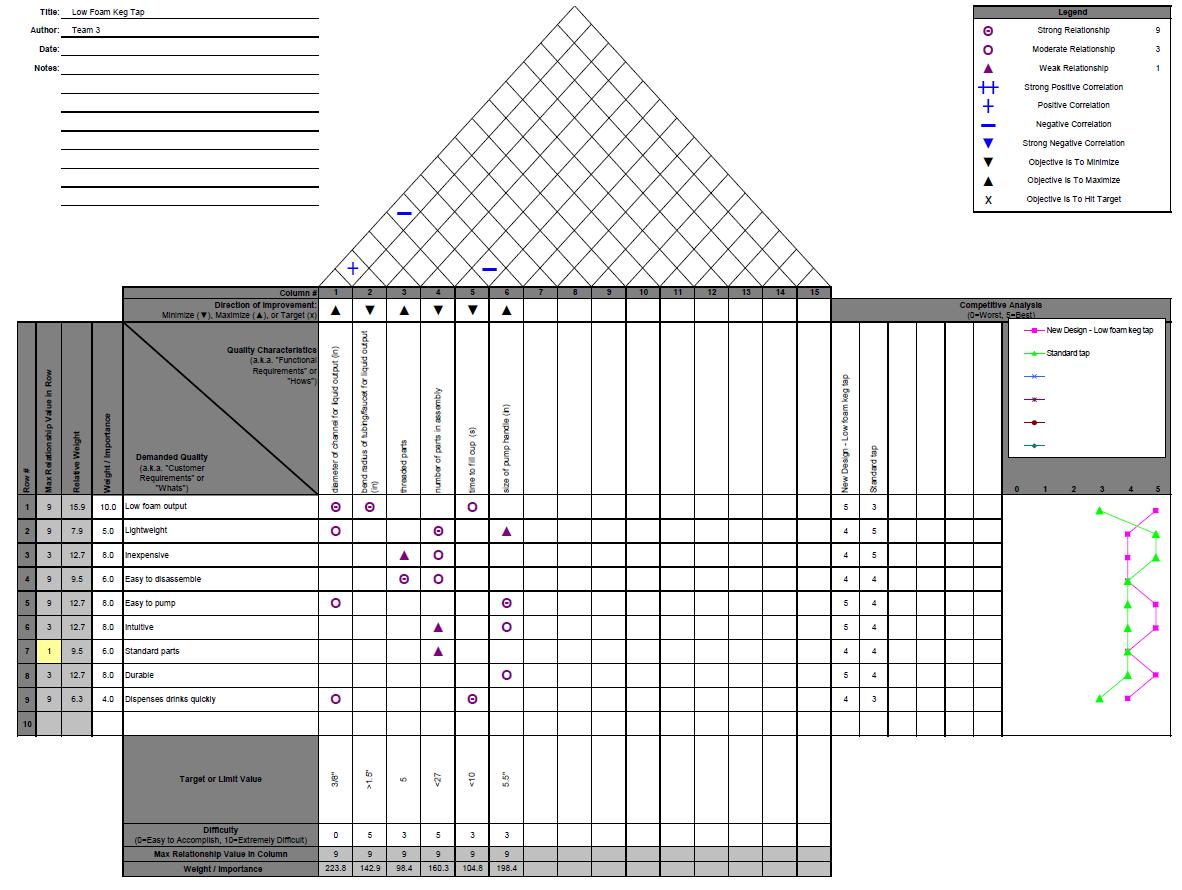
There are twelve customer requirements that we have identified for our product. The first is the ease of attaching and detaching the removable scraper. This is important because this effort is in lieu of taking out a scraper and scraping the windshield yourself. The priority is pretty high, since the product wouldn't be useful if it didn't surpass a scraper in ease of attachment. The second requirement is that the device be light weight. Since you must carry this to your wiper and attach it it should be easy to carry. The weight is especially important to cover an elderly demographic. The third requirement is that the blade not scratch the windshield. This has a high priority since scratching the windshield would reduce visibility and be a large cost to replace. The fourth requirement is to clear ice quickly, approximately within a minute. This was given a priority of 4 because it should be able to scrape more quickly than you could scrape with a scraper. The fifth requirement is to clear snow quickly, in one wipe. This also has a relatively high priority for the same reason. The sixth requirement is that the product be aesthetically pleasing. This was given a low priority since the product is detachable and thus is not visible at all times. Also, in relation to functionality aesthetics are not important. The seventh requirement is that the mounts should be easy to install. This was given a medium importance, because the mounts should not be impossible to install. However, they are self-install so consumers will have to take some time to put them on the wipers. The eighth requirement is for the device to fit a variety of windshield wipers. This is also of medium importance because the product should be able to be used by the majority of consumers. The ninth requirement is that the device last a few years. This is not of great importance because wipers themselves need replacing about every six months so it would be easy to also replace the scraper device at that time. The tenth requirement, and most important, is safety. The scraper blade should in no way make the vehicle unsafe to drive or harm the user. The eleventh requirement is cost. This is of relatively high priority because the price should be around the price of scrapers so that consumers will be more inclined to buy this product. The final requirement is storage. This is important because the users will be taking the scraper device on and off of the windshield and storing it in their car.
Product Design Requirements
There are six product design requirements that we have identified for our product. The first is that the device should be lightweight. This requirement was also identified in the customer requirements. The second requirement is that the device not obstruct vision. The mounts of the product are the only non-detachable part, so they should be made to fit within the profile of the wiper. The third requirement is that the blade conforms to the windshield. This is important so that all the ice and snow get scraped off and leave no streaks. The fourth requirement is that there not be a lot of force required to attach the scraper device. Again, the requirement was also listed among the customer requirements. The fifth requirement is that the force of the snow and ice do not cause the wipers to twist. If the wipers twisted it would damage them and probably scrape the windshield, which would be unsafe and costly. The final product design requirement is that the blade not scratch the windshield. This was also listed among the customer requirements.
Conclusions
As a result of performing a QFD we have learned that the product design requirement with the highest importance rating is that the blade conform to the windshield. To meet this requirement we performed an analysis on what the curvature of the blade should be (see mechanical analysis section). Though we do not have the means to mold our own ABS blade, we used a plexi-glass blade for our prototype. We heat treated the blade in order to put a curve in it. We tested out several different curves to get one that conformed to the windshield mock-up that we made. The second most important requirement was that the blade doesn't scratch the windshield. For the prototype we tested on several cars and verified that the plexi-glass did not scratch the windshield. For the final product the blade will be made out of ABS, which is the material most scrapers are made out of, so it will not scratch the windshield. In terms of how well we are performing compared to competitors, we seem to have them beat in most of the higher-priority areas. We fall behind in terms of some requirements but those are generally the ones of lesser value.
Final Prototype
Our final prototype is a dramatic improvement from our second prototype and is conceptually very close to what we propose for our final design. Similarly to our second prototype, the attachable blade mounts onto an existing wiper by twisting the tabs on the handles into the slots on the mounts. The blade in our final prototype differs from our previous prototype because we eliminated the need for springs and obtained a curvature through a heat treatment process.
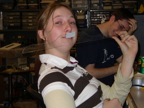
We originally chose Plexiglas as a material for the blade because it is durable and easy to mold. Plexiglas is well noted for its weather resistance and is commonly used in exterior applications, including the lenses of exterior lights of automobiles. Since our blade obtains a curvature through heat treatment, maintaining this form was initially a concern. However, plexiglas does not become pliable until 180 degrees F, and is not affected by cold temperatures. We also found that throughout extended periods of use, plexiglas is not highly susceptible to shrinkage or deterioration, but it is susceptible to cracking and chipping under certain conditions. As shown by the picture on the right, we discovered that plexiglas can crack relatively easily. For this reason, we will use ABS for our final design of the blade. ABS can be molded to form a curvature but is still elastic enough to not damage the windshield.
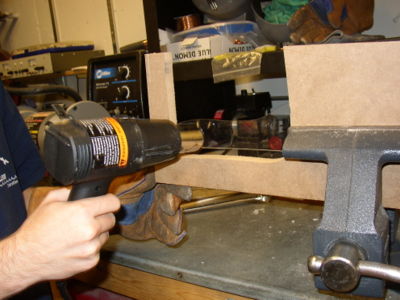
We formed a curvature in the plexiglas blade by treating the material with a heat gun. Based on our analysis of the desirable curvature, we placed the blade in a form (shown here) and then applied 1000 degrees F with a Milwaukee 1200 Watt heat gun for approximately 20 seconds.
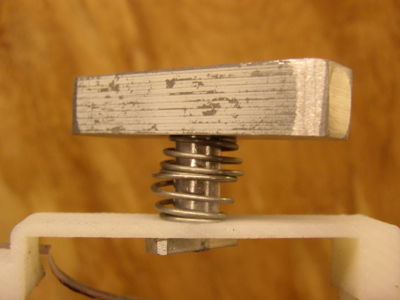
The handle for our prototype is comprised of a knob, a cylindrical block, a tab, and a spring. The knob is designed to be large enough that it is easy to grasp with gloves and the tab is small enough that it can slide securely into the slots without sticking out more than necessary. For this prototype the knob and block were machined as one piece of 6061 aluminum, and then threaded into the aluminum tab. We found that with use, the tab would become slightly unthreaded and would become difficult to install. For our final design, we are changing the material of the mentioned parts to ABS and securing the tab into the base with a thread locking treatment. This extra step in the assembly process will ultimately save consumer time and money from having to replace ineffective handles. From our previously discussed analysis, we know that the optimal spring has a spring constant of 6.87 lbs/in, a length of .16 in, and 3lbs of force when fully compressed. Since we could not acquire these springs for our final prototype, we found that a combination of the two springs shown here offer similar qualities to the one previous discussed.
The chassis is shown below with the handles attached. The chassis for our prototype was machined on a 3D printer out of ABS. Our final design of the chassis will be the same as the one for our prototype. The ABS blade for the final design will be mounted in the same way as the current plexiglas blade. This will provide additional support for the blade and will allow us to use a clear ABS for the blade.
The mount is made out of 6061 aluminum for our final prototype and also the final design. The design for our prototype include a circular groove for the block of the handle that attaches the handle and chassis securely to the wiper. As shown below, there are currently two holes in each mount that screw into the base part to secure the mount to the wiper. For our final design, we will have at least one additional screw connecting the mount to the wiper. This will allow our product to attach to a wide range of wipers.

Testing of Final Prototype
Display
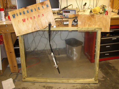
To demonstrate the effectiveness of our wiper attachment for the Design Expo, we created a working model of a windshield wiper. Our display of our final prototype includes the original wiper motor, a single wiper arm, the attachment we designed, and a curved sheet of Plexiglas to represent a windshield.
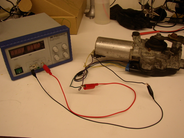
The windshield wiper motor shown below is from a 1996 Corsica. It is hooked up to a power supply which provides 12 Volts, 3 Amps to the motor. The power output of the motor is 36 watts (36W=12V*3A). Power = Voltage * Current
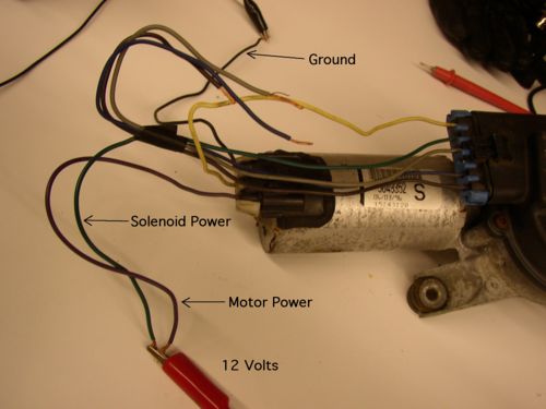
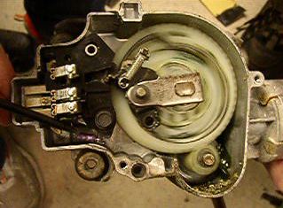
The picture below is a close-up of the wiring necessary to run the wipers. The black wire is ground, the purple wire supply the motor with power, and the green wire provides the solenoid with power. The solenoid acts as a switch to that allows a continuous rotation of the internal linkages. If this wire is not short circuited, as shown below, the first link will not rotate, and rotation will not be supplied to the wiper arm. Manual activation of this switch is can be viewed by clicking on the link: [3]. In this video, the switch is activated at the beginning and end of the clip. When the solenoid is supplied with power, the black switch is activated (thus putting the purple spring is put in tension) and the internal linkage rotates by fitting in the keyhole of the helical gear. When the solenoid is not supplied with power the internal linkage is fixed, causing a mechanism to snap into the keyhole once per rotation. We believe that this mode is necessary for a storage position of the wipers, causing them to fit under the hood. In actual use, the helical gear would only have one rotation on this this mode and would be activated at the end of wiper use.
As shown in the picture above, the motor translates rotational power to the wiper arms by a combination of a helical and worm gear. This gear train can increase the torque supplied to the wipers as well as slow the output speed to a desirable level. Worms gears are unique in that due to the angle of the teeth they can turn gears, but cannot be turned by other gears. This quality is good for windshield wiper motors because it acts as a locking system, preventing backspin. Helical gears are beneficial in this system because they are more quiet than most gears and are thrust bearing.
Feedback on our Prototype
In addition to the user-feedback we received from testing our product on a car, we spoke with many people that came by the booth at the Design Expo. They had very positive reactions to the idea because they liked the idea of sitting in their car and watching the windshield wiper scrapers take care of getting the ice off their car. A couple people commented that they where surprised that there was not something like this already on the market. There where a few people that where worried that it would scrape their windshield but once it was explained that the blade would be made out of the same material that scrapers are made out of there fears where allayed.
Should the design be pursued for production?
At this point in the design process, we cannot give a green light to go ahead with production. However, the design is promising, and with further technical testing and market research, the product could feasibly become approved for production. The first immediate obstacle is that the product needs to be tested in a large variety of extreme weather conditions; the team in Pittsburgh was unable to test the product in anything other than light snowy weather due to a shortage of willing car owners and lack of control over the weather. Our intuition is that the product will successfully scrape light to medium amounts of ice of the windshield, although we forsee troubles in conditions where the wiper itself is frozen.
Next Steps
The above testing in icy conditions will need to be done; this testing will give insight into product performance and potential problems. If the product is unable to scrape even the easiest ice off of windshields, then the product should probably be abandoned. However, if the product shows promise during the tests, which we expect it to, then we recommend one more round of revisions to deal with any problems in removing tough ice (the plastic might need to be thicker, the shape of the blade might need to be changed). In field product testing provided extremely valuable feedback during our prototyping phase, and we expect it to continue to do so.
Another avenue which should be explored is whether or not a "permanently attached" ice scraper is feasible. The group was able to confirm that short amounts of ABS to windshield scraping does not damage the windshield, however, if the scraper were on the windshield wipers all the time there is potential for damage. Once this concern is allayed, the design team can begin to design this permanently mounted scraper. The handles can be removed, and the chassis can permanently screw into the tapped blocks, the same way the mounting pieces are attached in the current design. This will allow the design to be simpler, shorter, and less obtrusive. In fact, by shortening the height off of the windshield and increasing the angle of the scraper blade slightly, the entire device should not obstruct vision at all and could permit driving with the scrapers attached. This product line could be extremely successful, since it would combine all the benefits of the current design, but remove the downside of required attachment and removal of the scraper after each use.
Team Contributions
During the early stages of the project team members took on equivalent roles as brainstormers and innovators. We held several meetings to brainstorm creative ideas to improve windshield wipers. During our brainstorming meetings we held a common meeting structure. We sat in a circle and went around clock-wise giving each person a turn to say an idea, add to an existing idea, or pass. Once each group member passed we either came up with a new topic to brainstorm or ended the meeting. Using this process we generated almost 100 ideas for windshield wiper improvements. During these meetings we came up with a few rules. Only one person was allowed to talk at a time. No negative feedback was tolerated. Also, we encouraged wild ideas. After we had a list of ideas we needed to narrow it down to our top 4 or 5. To do this we printed out the list of ideas and gave one to each group member. Each group member was then given the task of check marking the ideas they liked best, there was a limit of 5 double-checks(which had more weight) and an unlimited number of checks. We tallied and combined the totals from each persons list and came up with a new ranked list of our ideas. We first went through this new list and eliminated any ideas that we could agree either weren't feasible or pleasing. Once those ideas were gone, we were down to a list of about 13 idea. At this point we ran into some conflict. Different group members strongly preferred different projects and we struggled to talk through the designs. We ended up creating categories and merging several of our ideas. This led to our four main ideas of report 2.
It was fairly clear that various group members favored two of our main ideas: detachable wiper blades meant to reduce the cost and environmental impact of replacing the blades, and the windshield wiper scraper blade. At this point, we imagined that the scraper blade would be electronically activated, and a motor would lift and lower the blade onto the windshield. After discussing what technical details each project would entail, the group seemed to be at a three-to-one standstill in favor of the scraper blade, and so it was simply decided to pursue that project, with the hope of merging the two ideas if possible during the technical development.
From this point, we created prototype one, which showed the concept of our scraper blade attachment. From the early stages of work on prototype one, we realized that using an actuated scraper blade would be extremely difficult, if not impossible for our project with our schedule and budget. We performed some market research and realized that car owners would still be receptive to our product even if they had to manually activate and remove our scraper blade. This led to our prototype one, a simple concept showing a plexiglas scraper blade removably mounted to the windshield wiper.
From here, the technical challenges truly began, and group roles began to form. The group agreed on some general concepts to attain easy attachability and detachability, and a rough design was created. During this construction phase, we realized that there were several details that we would need to work through to implement spring-loaded handles. We hadn't fully flushed out our design before construction, so this prototype two phase was critical in working through most of the design problems. Prototype Two, while it was heavy and unsightly, showed successful proof of concept of two of our key design challenges: removability from the permanent mounts, and blade curvature and deformation by using tension springs.
Since we had the key design elements decided from prototype two, prototype three became an analysis and refinement exercise. The parts had to be finalized and dimensioned. During this time, we had to make decisions about exactly what the parts would be and how they would be made. DFM and DFA came into play since we strove to reduce the number and complexity of the parts used in our product. Materials were also selected.
Looking back, it is probably a good thing that we waited so long to perform our in-depth mechanical analyses. As we were making design decisions for our final prototype we realized that mechanical analysis would allow us to optimize parts and check that the parts were strong enough. Anne Marie performed stress analysis calculations to augment our FMEA and to check that our final parts would be sufficiently strong. Kevin performed spring optimization and blade curvature analysis so that those design decisions could be made well. Justine performed a QFD analysis and determined which were the most important areas to concentrate on. Erika took charge of the DFM and DFA, and we were successfully able to remove several screws from the design.
From here, we began constructing our final prototype. Justine, with the most machining experience, and Kevin worked together to create the the aluminum parts. We 3-d printed our much lighter chassis, and our final prototype came together.
We realized that testing our product would be crucial, so we worked with a willing car owner to install our mounts and scraper on their windshield wiper. We were successfully able to scrape away snow, as well as confirm that our product was safe to use on real cars.
For most of the reports the work was split evenly and done individually at first. Closer to the report date, we would meet together combine our sections and read over each others work, making corrections and giving additional insight. This is in contrast to the design decisions, which were usually made as a group.
The following are titles which embody the spirit of each group member during the project:
Erika Bannon - Manufacturing and Assembly Consultant
Anne Marie Lewis - Chief Scientist
Kevin Lipkin - Mechanical Analyst
Justine Rembisz - Head Machinist
References
Java Injection Molding Cost Estimator
[[4]]
LanXess websight:
[[5]]
PDF of propties of Lustran ABS 433 when using it for injection molding:
[[6]]

