Snowboard binding
From DDL Wiki
Team 7:
Hamilton, Sean
Karoubalis, Spiro
Li, Michael
Santiago, Kaila
Contents |
Executive Summary
We have noted several areas for improvement that we will be looking to enhance in the coming weeks. First, the adjustment of the angle of the binding requires a screwdriver and a substantial amount of time and discomfort for the rider making his adjustment without snow gloves. Second, the majority of the product is made out of plastic, which can be damaging to the environment. Third, the snowboard base and hi back could use less material, thus reducing costs for the manufacturer and increasing performance through weight reduction and easier product transport.
As part of our analysis we conclude that this is an easy market for Initech to enter. Most snowboard bindings are similar in design and function. The manufacturing costs are mostly in upfront expenses such as molds and dyes that can be paid off with mass production of the product. Upon addition of a unique feature or function, Initech could quickly jump to the front of the snowboard binding market. We will be providing our recommendation for Initech’s future enhancement to the binding in the coming months.
Stakeholders
We have identified three major stakeholders in snowboard bindings: the Customer, the Manufacturer, and the Retailer. All have something to be gained from decisions about the product which is identified in detail below.
Customers: Customers are the primary users of the snowboard bindings. They benefit from a low cost product with durable materials capable of both providing enough support for high performance use but also materials that are flexible and light weight enough for easy transportation and safe use in the event of an accident. In addition, customers value convenience, comfort, and ease of use including entry and removal of the boot. Customers also use various different types of boots to snowboard. Our product will need to meet that stakeholder requirement by being capable of securing as many different boot types as is cost effective.
- The product must be of high quality materials and durable enough for use in extreme conditions. Customers would not purchase a product that does not enable them to remain attached to the board while in use.
- The product must be relatively light weight for ease of transportation. Snowboarders will be carrying the board and attached bindings to and from the mountain, sometimes over long distances. We would like to limit the weight in the bindings to increase comfort of cross ground carrying.
- The product needs to be able to be used by all types of users of all ages and skill levels.
- Needs to be easy to operate with gloves on.
- Needs to operate in cold weather (durable).
- Customers are also concerned about the following factors:
- Cost
- Ease of strapping in
- Speed of strapping in
- Ease of Removal
- Comfort
- Use with many boot types
- Entry from standing and sitting position
- Aesthetics
- Ease of storage
- Ability to customize
- Safety
- Reliability
Manufacturers are impacted by the ease of manufacture and assembly of the product.
- Materials, manufacturing, and assembly costs
- Part Count (ideally low)
- Transportation costs (from moving raw materials to manufacturing location)
- Production time: Manufacturers are impacted by how long it takes to produce the product
Retailers are impacted by packaging, price and other factors.
- Ease of storage: for transportation, warehousing, and displaying
- Size of package: to maximize use of store floor space
- Needs to be lightweight to lower transportation costs
User Study
Snowboard bindings are essential to the functionality of the sport. The bindings enable the rider to use his/her body weight to control the snowboard. The mounting disc of the bindings functions as the sole attachment that keeps the bindings from disconnecting from the board. Strap-in bindings are most commonly used on the mountain. The binding examined was a 5150 binding.
Initial Assembly:
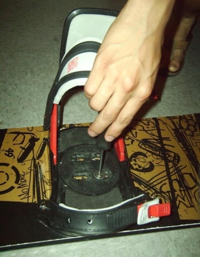
The use of the bindings is relatively simple. The rider first begins by attaching the bindings to the board. To do this, the rider must first decide what angle he wishes the mounting disc to be set. The rider then aligns the mounting disc slots and screws in the mounting disc (four screw locations, using a philips head screwdriver). Based on the style of riding preferred, the rider may also adjust the hi back support using the forward lean adjustment tab.
With the mounting disc in place, the rider can then insert his snowboarding boot into the binding.
Ideally, the rider straps in first using the upper strap, followed by the toe strap, and then adjusts the ratchets to the desired support.
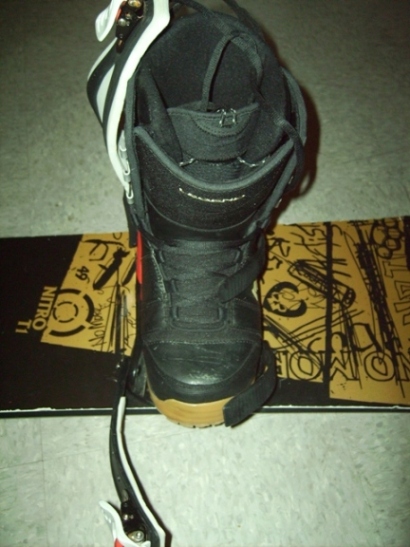
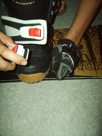
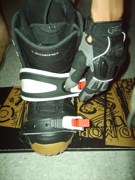
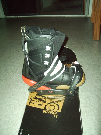
This procedure becomes more complicated when snow gloves are involved, as the ratchets and mounting disc are more difficult to adjust. During our user study, we asked a potential end use customer to change the angle of the mounting disc, as he would on the top of the mountain if he wanted to switch styles of riding. In order to do this, the customer was required to remove the boot, unscrew the mounting disc, and repeat the steps listed above. This process became much more time consuming when we asked the rider to repeat the process with a snowboard glove on. After averaging the times recorded during the user study, we found it took about five minutes without gloves to assemble both bindings, where as it took about nine minutes with gloves.
Areas for Improvement:
After analyzing the ease of use, we found the following that could increase the usability of the binding:
Mounting Disc- Removing gloves and rotating the mounting disc would be very difficult to do in very cold temperatures, often encountered while snowboarding. In order to improve comfort for the rider, we suggest the mounting disc be adjustable without completely detaching the binding from the snowboard, and with the rider wearing gloves.
Ratchet Buckle- We realized during the user study that with gloves on it is difficult to adjust the ratchet buckle to the desired tightness. In order to improve the usability of the binding we recommend an increase in size of the buckle giving users greater leverage to obtain the desired fit. In addition to increased size and lever arm we recommend the buckle be forged with additional ribbing near the end of the lever making users less likely to slip off the buckle when tightening after the binding has become wet from use.
Pictures of Assembly
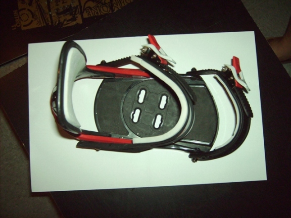
Below are some images of the snowboard and binding components. The individual components of the bindings are shown zoomed in, but for a better view of each individual component, please refer to the Bill of Materials.
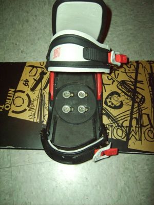
The Snowboard
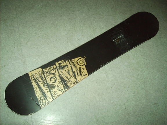
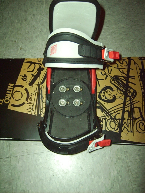
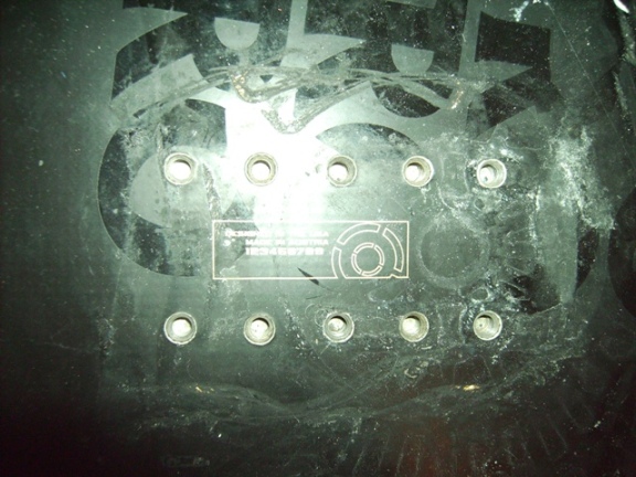
Where the bindings are mounted
Overhead of Snowboard binding assembly
Ankle strap ratchet buckle

Toe strap ratchet buckle

Ankle strap; consists of ankle riser, long ladder, padded ankle strap, and ankle ratchet buckle
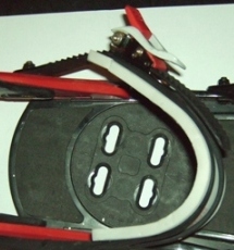
Toe strap; consists of toe riser, toe ladder, padded toe strap, and toe ratchet buckle
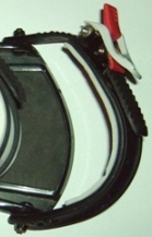
High Back (Hi Back)
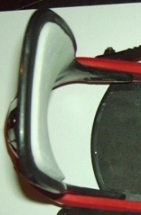
Bill of Materials
The following is a parts list of all the components that make up ONE snowboard binding (as in the left or right, but not both). Included are: the weight of each component, the material which it is made of, the manufacturing process, and a picture of the component, totaling 63 parts to each binding. While many of these parts are nuts, bolts, and washers, it shows that there is more complexity to a binding than one might expect.
Function: how each component functions
Below are some more descriptions of major components.
Part #6: Toe Ladder Strap – Attached to the base plate, the toe ladder strap engages with the toe ratchet buckle to secure the padded toe strap over the toe of the snowboard boot. Provides leverage for increased heel edge power.
Part #9-17: Toe ratchet buckle – Engages with the toe ladder strap and is fixed to the padded toe strap. Allows the user to quickly adjust the overall length of the toe strap with a ratchet system. Ensures that the snowboard boot’s toe section is secured to the base plate of the binding. Also features a quick ladder strap release lever.
Part #3: Long ladder Strap – Also attached to the base plate, the long ladder strap engages with the ankle ratchet buckle to secure the padded ankle strap over the ankle portion of the snowboard boot. Provides leverage for increased toe edge power.
Part #33 and 36: Ankle Riser - Secures the other side of the padded ankle strap to the base plate. Allows for padded ankle strap adjustment; the ankle riser can shorten or lengthen the overall ankle strap length.
Part #9-17: Ankle ratchet buckle - Engages with the long ladder strap and is fixed to the padded ankle strap. Allows the user to quickly adjust the overall length of the ankle strap with a ratchet system. Ensures that the snowboard boot’s ankle section is secured to the base plate of the binding. Also features a quick ladder strap release lever.
Part #5 and 7: Hi back – Cupped to fit around the back of the snowboard boot. Pressing on the hi back increases heel edge power. The angle and height of the hi back affects performance. A greater angle or a higher hi back results in greater heel edge power. A smaller forward lean or lower hi back results in more comfort and boot movement freedom.
Part #2: Base plate – The component between the snowboard boot and snowboard deck. Serves as padding for increased shock absorption capabilities. Because it increases the distance between the snowboard and snowboard boot, the base plate also reduces toe drag.
Part #4: Heel cup – Controls how far off the snowboard the heel of the snowboard boot hangs. Provides heel support and prevents rotation of the boots while strapped in. Attached to the base plate and hi back.
Part #1: Mounting Disc – This component mates the binding base plate to the snowboard deck. Fits into the base plate to determine binding mount angle. Typically has four slots in which four screws and washers fit and secure the binding to the snowboard. Also improves shock absorption abilities of the overall binding.
Design for Manufacturing and Assembly
Design for Manufacturing
The majority of the parts in the snowboard boot binding are made of injection molded plastic. This makes the production cost for many of the parts relatively low. Injection molding plastic can be manufactured relatively rapidly after the initial creation of the mold. In addition to speed, injection molding carries a low cost per part for large batch sizes. Similarly the clips and ratchets are made out of a form of aluminum most likely cast from a mold. Casting metal is more expensive than injection molding plastic however, both carry high initial costs and minimal costs during production. The springs, rivets, and beams would all be made out of a continuous flow process of steel. In continuous flow processes, molten metal is forced through a die of the desired dimensions and shape and is cut to the desired length. Springs are formed by bending the metal while it is in a semi-molten stage while screws are processed by thread molding systems of parallel plates. Both processes are automated and relatively inexpensive in large quantities.
In addition, the current design maintains a low part count with all components standardized. Injection molded plastic is relatively easy to fabricate and can be colored in the injection process to cut out paint processing time. In conclusion, the snowboard boot binding appears to be designed in such a way to be most effective for manufacturing. The designers made smart design decisions to limit additional work and expenses in producing the product.
Materials Selection
The materials selected are plastic, aluminum, steel and foam for all of the primary components of the snowboard binding. These materials represent what seems to be the most effective use of these materials. The plastic used is cheap but thick to give additional support and rigidity to the binding. Metal is only used in parts that are under the greatest stresses during use, such as the screws keeping the binding attached and the clips that create tension on the straps. The foam that is used is relatively high density in order to provide the most padding over the longest time. There are two types of plastic present in the binding: a more rigid kind used in the frame of the binding and a flexible kind used in the ratcheting straps. This is a smart choice in that it ensures high structural integrity of the frame of the binding while still ensuring it can be tightened to a custom level with very little difficulty.
Design for Assembly
The snowboard boot binding has clearly been designed with assembly in mind. The majority of the components of the binding are large and plastic making them easy to handle. In addition, many come with snap fittings which not only make it simple for assembly line employees to connect but also allowed the customer the ability to adjust his settings based on an array of holes in the part, increasing the ability to customize. Also, all of the screws from the larger components can be adjusted with the same Phillips head screwdriver. This would ensure minimal wasted time between assembly processes for changing tools.
The most complicated portion of the binding is the ratcheting clip sub-assembly which contains various small parts, screws, and rivets. The part is already designed well in that there is only one way to fit together the two halves of the cast aluminum clip. However, the size of the components within the sub-assembly would make for a delicate task for any assembly line employee.
In conclusion, the competitor binding has been designed with the assembly process in mind throughout the majority of the process. Large, easy to snap together parts, a low overall part count and mistake proof shapes make the plastic components of the binding easy to assemble. However, the small binding clips with numerous rivets and sub-components would be a challenge to put together effectively for even a trained assembly line employee. Our suggestion would be to make the clip larger in order to allow greater freedoms of the assembly person. There would be no change to performance or aesthetics, a slight increase in materials cost, however it would reduce assembly time allowing for more cost effective production.
Failure Modes and Effects Analysis
Failure modes and effects analysis (FMEA) is an effective tool in identifying a product’s strengths and weaknesses. The process begins by listing all components/parts of a product. Each component is then analyzed to determine different possible failure modes and effects of each failure mode. The failures are rated according to the legend below. The failures and effects of failures are assessed on a scale from 1 to 10, 1 being lowest and 10 highest. Finally, a recommended action may be proposed if necessary and each component is reevaluated (*).
The table below lists the separate components of a snowboard binding and assesses different modes in which these components may fail.
Legend :
(S) – Severity of the Failure
(O) – rate of occurrence
(D) – Detectability of the problem
RPN – Risk Priority Number; = S*O*D
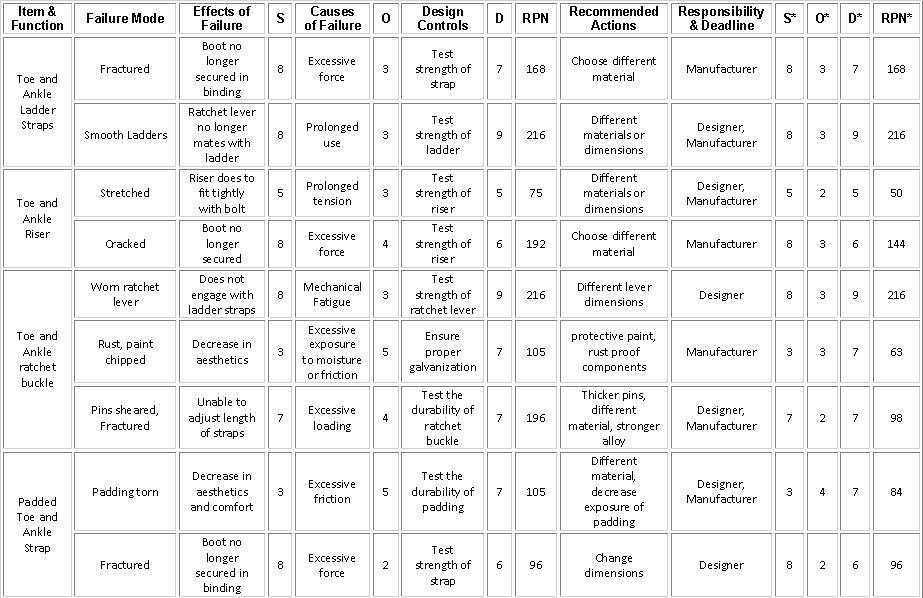
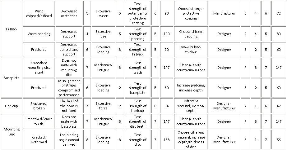

Our FMEA analysis yielded highly positive results. Based on the original design the major faults of the product do not result in highly destructive outcomes. In order to combat the most common and dangerous possible sources of failure we recommend the following adjustments. In order to prevent the boot from becoming unsecured we recommend increasing the strength or thickness of the ladder straps to ensure the boot remains secured despite the roughest riding conditions. We also recommend increased galvanization of the metal buckles as during use they are often subject to water and friction. This processing would help preserve the aesthetics of the binding buckle.
Overall, the bindings are safe to use. All components are unlikely to fail under normal circumstances and require no major redesign. Therefore, in the future, it will be interesting to look into introduction of a new component(s) as opposed to redesigning an existing component.
Design for Environment
Recent growing concerns over human environmental impact have stirred engineers to become more aware of their designs and the impact on the environment. This growing awareness brings about a new engineering aspect entitled “Design for Environment”. In our analysis of the snowboard binding, we considered various guidelines when determining the product’s environmental influence. Since the usage of the product does not require any external sources or energy input (besides that of the user).Therefore, we have found the analysis of the environmental impacts of snowboard binding usage negligible.
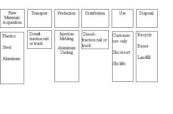
We used a template for analysis called Life Cycle Assessment (LCA) which examines each process associated with the manufacture, production, use, and disposal of the product. The following flow chart represents the various aspects of the life cycle of a snowboard binding.
We have used software that produces an Economic Input-Output LCA (EIO-LCA) in order to quickly analyze the chart above. This program uses industry sector averages to predict economic and environmental impact based on the supply chain needed to generate a given demand. The main material used in the life cycle for the product is plastic, and we have therefore chosen to use the model for “Other Plastic Product Manufacturing” sector for a design for environment analysis.
Manufacturing
Economic Activity
The results show that the main economic activity in producing a demand of one million dollars is credited towards other plastics product manufacturing. These results predict that for the demand given, we can assume a total economic activity increase of $2.36 million.

Greenhouse Gas Emissions
The results of the EIO-LCA show an increase of 862 metric tons of CO2 equivalent (MTCO2E) per $1 million increase in demand for snowboard bindings. This increase is mainly attributed to the power generation and supply needed to manufacture the plastic products. We have noted that the predicted emissions associated with other plastics product manufacturing accounts for only 4% of total greenhouse gas emissions.

Energy
Inducing a demand of $1 million produces a predicted energy increase of 14.7 terajoules (TJ) for all sectors. Again, we see the main source for this increased energy demand stems from power generation and supply, as well as from plastic material and resin manufacturing.
Both energy demand and greenhouse gas emission results from the EIO-LCA list truck transportation as a top ten contributor to environmental effect. The product features components that can be easily stacked and folded. Based on this design of the product, we feel that the packing design has been optimized and allows for maximum efficiency in transporting the product.
End Use/Disposal
The design of the product involves various components which can easily be disassembled, therefore providing optimum end-use efficiency. Separate components can be replaced upon failure instead of replacing the entire product assembly.
The toe and upper straps of the binding contain a comfort foam strip attached to the plastic which interferes with recycling. A recommendation here would be to re-design the straps so that the foam strip can be easily removed prior to disposal.
Conclusions
Based on the results found from our EIO-LCA analysis, the main environmental impacts are attributed to the power generation and supply needed to support an increased product demand of $1 million dollars. Given that the usage of the product results in nominal (or no) environmental impact, almost all impact is attributed to the production of the snowboard binding. A carbon tax, if imposed by the US government, would have negligible effects on the cost of materials and production of the binding. Based on a carbon tax of 4.4 cent per ton, as imposed by Bay Area Air Quality Management, would increase the cost of production and materials by only $34 per million dollar sector increase (Los Angeles Times, 2008). Since the use of the binding requires no additional energy input (except by the user), this would represent only a 0.0034% increase, which can be neglected.
In order to decrease the environmental effects of producing the binding, one could look at incorporating more energy efficient manufacturing methods, as well as using biodegradable plastics. A more detailed analysis of using biodegradable material in injection molding (main manufacturing method used) should be conducted in order to recommend the use of a specific bio-plastic.
The vast majority of the binding consists of plastic materials. There were a small number of metallic components that were not included in this analysis, as their impact was assumed to be negligible. Also, the use of online software to perform an EIO-LCA produces very general and basic results. To add to this inaccuracy, the software did not specify snowboard bindings as a source for Other Plastics Product Manufacturing. A further study would include a more accurate data source/software, as well as including the excluded components. We feel that these inaccuracies did not affect the basic design for environment analysis of the product, nor did it affect our ability to provide recommendations for improving the product.
Mechanical Analysis
The following image is a close up picture of one of the two ratcheting mechanisms that can be found on each snow board binding. The two red arrows indicate estimates of where forces are exerted on the ratchet tightening lever. Point A is located at the center of the rivet which the ratchet tightening lever is hinged upon. F(1) is the force that the users hand would exert when tightening the binding strap, while F(2) is the force resulting from the tension in the ladder straps.

Moments About Large Rivet At Point A
To determine moments around Point A, we first had to determine an average maximum force exerted on the lever when the bindings were being tightened around the boot. To do this, we tightened the bindings very tightly by hand. We then hung weights off of the end of the tightening lever. We added weight until the tightening lever tightened the straps one more click. This force was taken to be what the user exerted on the tightening lever when using the snowboard bindings. In our case, it was about 15 lbs.
Pound to Newton Conversion
15 lb * 4.448 N/lb 66.72 N
F1 = Force exerted by hand
F2 = Force exerted by tension in ladder straps
d1 = 0.040m
d2 = 0.009m
-F1d1 + F2d2 = 0
66.72 N * 0.040 m = F2 * 0.009 m
F2 = 296.53 N = 66.66 lb
Reaction Force At Point A
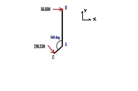
Bx = 66.66 N
By = 0.0 N
Cx = (296.53 N) * sin(50o) = 227.16
Cy = -(296.53 N) * cos(50o) = -190.61
Sum Fx = 66.66 N + 227.16 = 293.83
Sum Fy = 0.0 N - 190.61 = -190.61
FA2 = 293.832 N + 190.612 N = (350.23 N)2
FA = 350.23 N
Because the rivet is supported at two ends, the 350.23 N shear force should be divided by two. This value is still a much larger one than we expected to see, an we were surprised that the small piece of metal was able to handle such loads.
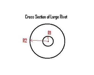
To find the Shear Stress in the large Rivet, we use the following equation:
Tmax = 4V/3A
where V = shear force and A = cross sectional area
R1 = 0.001 m
R2 = 0.0005 m
V = 350.23 N / 2 = 175.11 N
A = pi*( (R2)2 - (R1)1) )
A = 3.14*((.0015 m)2-(0.0005 m)2) = 6.283*10-6 m2
Tmax = ( 4*175.11 N ) / ( 3*6.283*10-6 m2 ) = 37,159,495.11 Pa = 37 MPa
The shear strength for stainless steel is approximately 260 MPa. This means that the rivet is far from failing.
CONCLUSION
The results of this mechanical analysis show that the maximum reaction forces on the rivet that are exerted on it by the tightening ratchet should never cause the rivet to snap. There is a safety factor of about 6 built into the rivet. This makes it significantly stronger than it needs to be, especially since it experiences no dynamic loads. It should be a piece that never fails during normal use.
Team Member Roles
Sean Hamilton: Stakeholders, DFMA, Executive Summary, Wiki
Kaila Santiago: User Study, DFE, Wiki
Spiro Kiroubalis: Mechanical Analysis, Dissection, Wiki
Michael Li: FMEA, Component Functions/images, Wiki
