Snowboard innovation
From DDL Wiki
Contents |
Executive Summary
From our initial market research of snowboards, we found that travelling either by car and plane was a cause of annoyance from snowboarders. These problems were due to the difficulties of transportation of a conventional snowboard. To remedy this need we envisioned a foldable snowboard that would eliminate the need of roofracks and special airplane luggage. Other secondary advantages of the foldable snowboard that we discovered later included easier storage for users living in a small room and the possibility of carrying the board in two pieces which is more confortable.
Our final design is a detachable snowboard that splits into two pieces giving more freedom of where to place or carry the two parts than our initial foldable design. The board functions by two latches that stop the board from sliding apart and inlaid titanium rods that restores the dynamics of the board, which are lost when cutting the board in half. The board is cut in a Z shape through the middle in order for there to be no weak line all the way across the board which could cause security issues.
We conducted several mechanical analyzes on the detachable snowboard design in order to optimize its static as well as mechanical properties. The tubes designed to restore the dynamics were optimized to have the lowest possible mass, while giving the detachable board the same deformation in bending as the original snowboard. This was tested with static experiments. We also conducted vibrational experiments on both the original snowboard and our prototype which were at the same time modeled using finite element analysis. A very good correlation between the FEA model and experiments was obtained and the natural frequencies of the prototype were found to be very similar to those of the original board. Static analysis was then done using FEA to verify that the bending of the board was acceptable.
Our mechanical analyzes show that this snowboard is physically viable and we believe there is a market for it. Furthermore this invention can also significantly reduce the CO2 footprint of snowboarding as roofracks on top of cars significantly increase drag. Especially considering that many leave their roof racks on the entire snowboarding season, the detachable snowboard could be a factor to making snowboarding more eco-friendly
Market Analysis
Detachable Snowboard Market
In our previous market research we concluded there is a user need for a snowboard that is easier to transport by car and plane, eliminating the need for roofracks and special snowboard luggage. There also exists a market for snowboard wall hangers, which could be eliminated by the easier storage of a detachable board.
After the exposition of our product to the public and the media we recieved great feedback. The public seemed to be intrigued by our design, but especially the fact that the TV channels CBS Pittsburgh and WTAE chose to show our product as well as interviews with our team members on their news, gave us feedback that the detachable snowboard has a high marketing potential [1][2].
In order to fully analyze if there is a possible market for a detachable snowboard we first looked at snowboarder demographics: [3]:
The general trend is that snowboarders tend to be young, male and rich. In the U.S. only 6% of the population make more than a 100,000$ per year [4], compared to 32,4% of snowboarders. A detachable snowboard will be more expensive than a regular board, however snowboarders being a rich demographic will be less influenced by price increases if they can be convinced of the advantages of the new design. Therfore we believe the cost increase will not deter those snowboarders interested in our product.
Furthermore we looked at the splitboard market. A splitboard is a snowboard that splits into cross-country skis, in order to let the user move outside ski slopes to get to unused powder snow. Splitboards began to appear in 1993, but did not become mainstream until 2-3 years ago with brands such as Burton and K2 beginning to produce splitboards [5]. While solving very different user needs, the dynamic difficulties experienced by the boards are similar, as they require a mechanism for keeping two the separate halves together in a way that as closely as possible mimics the dynamics of an original snowboard. Even though there have been great improvements on the quality of splitboards, they are not yet as good as regular snowboards. This would also be true for a detachable snowboard. However the splitboard market keeps growing each year [6]. We conclude from this that there exist a growing market for snowboards that solve secondary needs, while sacrificing some of the dynamic properties.
We identified our target markets to be fairly diverse. Possible buyers listed by their importance would include:
-Snowboarders looking to avoid the hassle of fixing the roofrack, lifting the board both up and down at home and at the resort, as well as detaching the roof rack. Instead two easy release clips will let them detach the snowboard and place it in the car trunk.
-Snowboarders who prefer to bring their own boards when going for an alpine vacation by airplane.
-New snowboarders who will avoid having to also buy a roofrack when buying a snowboard.
-Snowboarders who want to reduce their CO2 footprint by avoiding the roofrack, or to reduce their fuel costs.
-Students or others who have limited space in their rooms for easier storing.
Estimated Price
Next we analyzed what would be an approximate price of our detachable snowboard. New regular snowboards are sold from a minimum of 100$ and ranging all the way to 10million$ for the worlds most expensive motorized gold snowboard [7]. However in order to estimate the price of a detachable snowboard we mainly used splitboard prices. The cheapest splitboard commercially available costs 420$ and prices go up to around 800$ [8]. The reason we base our costs on a splitboard is that the cost of materials needed are approximately the same as a regular snowboard, but it requires a few extra operations to be produced. These include cutting the board and attaching the supports at the back, front and middle of the board. We approximate that the amount of extra labour to produce a detachable board will be the same as that of a splitboard. Thus the price of the detachable board will be the price of an average splitboard plus the cost of the titanium rods. Using mcmaster.com the price of the 8ft of a quarter inch diameter titanium tubes needed will be around 100$[9]. Considering an average price of 600$ for a splitboard (the price of most Burton and K2 splitboards), we were able to make a final estimate of 700$ for the detachable snowoard. However for a mass produced model, the price of the titanium tubes could be reduced and depending on the quality of the detachable snowboard the price could vary from around 600$-800$.
Estimated Production Volume
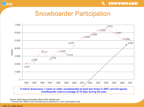
In order to estimate a production volume we begin by looking at total snowboarders: [10]:
There are around 5 million snowboarders in the U.S. and as am initial estimate we believe at least 1% market would be a potential buyer of the detachable snowboard, meaning 500,000 boards. However once again we consider the case of splitboards. One of todays four main splitboard companies Voilé began as a small company producing them in 1995, but from 1995 to 2000 they had only sold 2500 boards[11] . As seen on the graph, since then the total snowboard market has doubled and today Voilé is one of the market leaders of splitboards. There is a likelihood of the detachable snowboard following a similar very slow path of initial growth while they remain a niche product, before eventually having to compete against the large snowboard companies should it become a trend. We believe in order to make a profitable business producing and selling detachable snowboards a patent should be filed. If granted then with the help of university or venture capital funding we could begin producing around a 1000 snowboards the first year, and slowly increase production volume as detachable boards become more mainstream. Hopefully after a few years the production volume will have increased enough for a large snowboard company to either buy the patent or the company, eventually pay us for using the patent. With big company funding it should be possible to reach the initially estimated 1% marked share.
We then look at the total amount of revenue generated from snowboard sales: [12]
In 2008 the total sales generated 312.5 million$ of revenue. Taking 1% of this would be approximately 3 million dollars yearly and likely to increase each year which could be a potentially very interesting investment for a snowboard company if they could get a monopoly on this market.
Market Analysis Conclusion
Our main target market are snowboarders looking to simplify their snowboarding experience by eliminating the need for screwing and unscrewing their roofrack and lifting their boards up and attaching them to the roofrack, as well as snowboarders bringing their boards on air travel. The estimated price of this board would range from 600$-800$. The production would be expected to start slow at approximately a 1000 boards per year and possibly increase within 5-10 years to take a 1% market share meaning more than 500,000 boards per year, which could make it a several million dollar business. Therefore we recommend that the final design should be prototyped and further mechanical testing of the board should be performed as well as testing on the slopes to ensure the design is functional. Furthermore more extensive market research should be conducted on snowboarders to determine the percentage who would be interested in a detachable snowboard.
Design Documentation
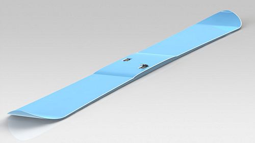
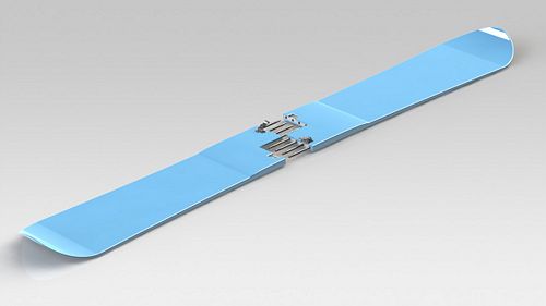
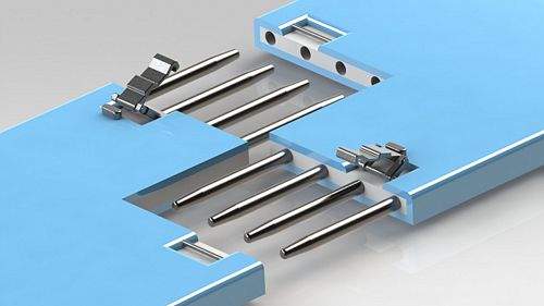
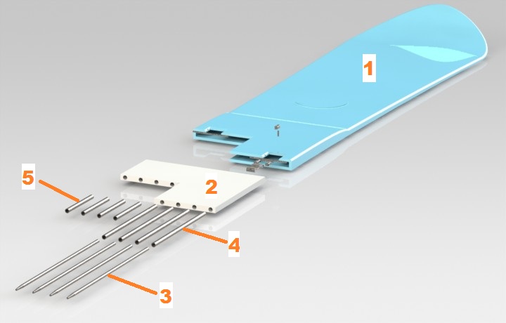
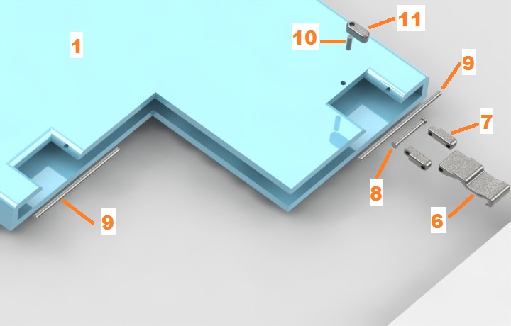
The final design is proposed here. It is justified by the mechanical analysis and FEA simulation of the final prototype as shown below. This final design was analyzed using modal FEA, and its natural frequencies were found to be within 25% of the original boards'. The design looks promising, and will be fully analyzed, prototyped, and tested given a renewed commitment from the client. As opposed to the prototype, this design incorporates all of the connection hardware into the body of the board. The midsection is thickened to accommodate the additional material on the inside. Tubes are embedded directly into the resin/fiberglass layup of the snowboard material, after which titanium rods are bonded to the tubes. This setup mitigates the loss of longitudinal and torsional rigidity incurred by splitting the board in two better than the prototype possibly can. Custom latches, built for high strength-to-weight ratio, are sunken into the top surface of each board half. They prevent the board halves from coming apart and add friction to the board half interface. The board is cut in a stepped fashion so that any straight line drawn across the board traverses a contiguous section at least as wide as half of the board at its most narrow point. This ensures board shape integrity even when landing jumps and grinding on rails near the cut interface. The board keeps a low profile as compared to the original prototype and will not interfere with a riders daily snowboarding actions. Its components are significantly less exposed than the components of the prototype, so and are thus more corrosion resistant and have a longer expected life.
The design is optimized for manufacture in a retooled board shop. The two halves are identical and interchangeable, which keeps the manufacturing process simple and streamlined. Few additional steps between the layup process and the final press-sintering are required to add the rods tubes, and latch attachments.
Final Design
Assembly
This is the exploded view of the assembly of the final product.
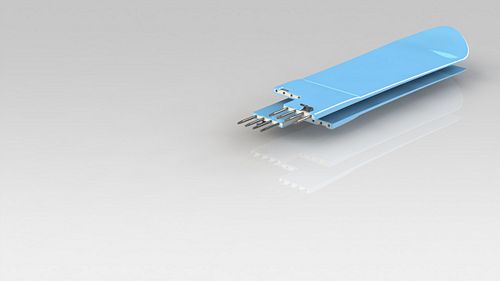
A closer look at the hinge.
Bill of Materials
All components of the final design are custom made, so a CAD drawing is included for each one. See Appendix A.
House of Quality
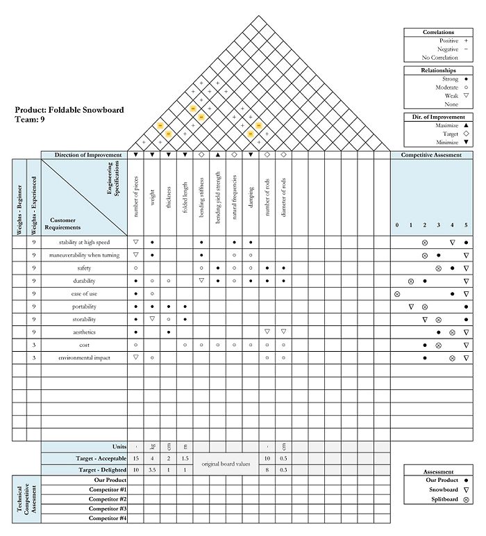
The House of Quality shows how our product compares against its competitors. We chose the two most relevant competitors, the regular board and the splitboard that was seen in the Market Research section. We compared them across a wide range of customer requirements, ranging from performance characteristics to transportability or ease of use. These requirements are valid for both beginners and experienced users, with beginners putting more emphasis on aesthetics and cost, and experience users giving more importance to performance characteristics.
Our product fare better than the splitboard in almost all categories. Compared to a regular board, our product is a lot easier to carry and store. While it is not as maneuverable when turning, its stability at high speed will appeal to experienced users that ride faster and do smooth turns. The regular snowboard is more durable, whereas the safety of our product is almost the same as the regular board, thanks to our mechanical analysis. Our product costs more, but it eliminates the need for buying a roof rack, which also leads to a reduction in the car's fuel consumption. The reduced CO2 emissions means the environmental impact of our product over its lifetime is smaller than for a regular snowboard.
Design Analysis
FMEA
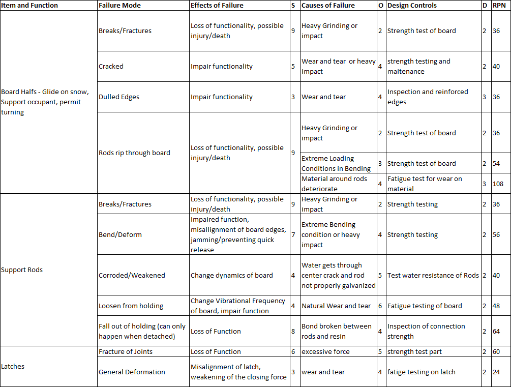
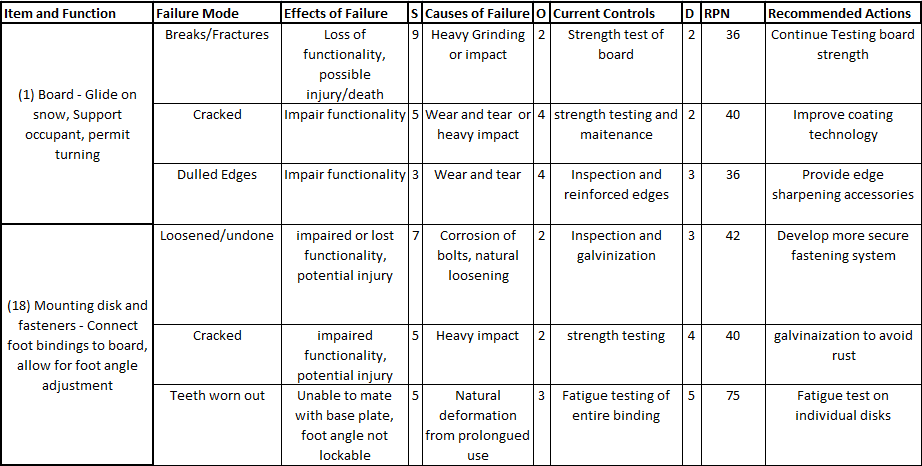
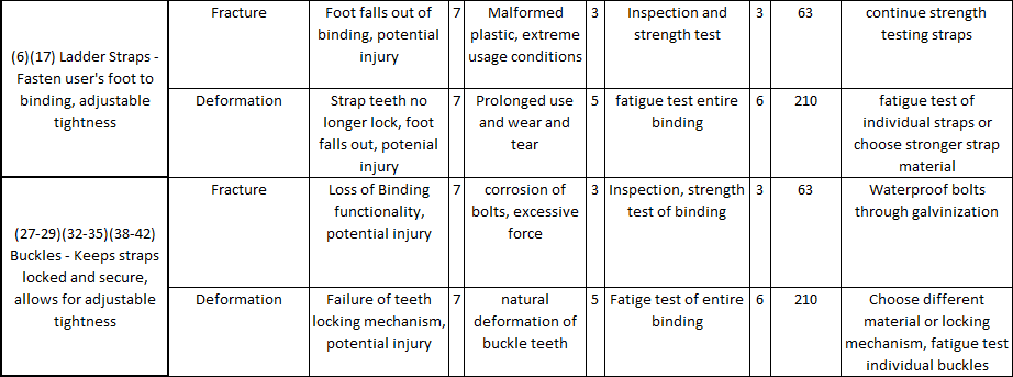
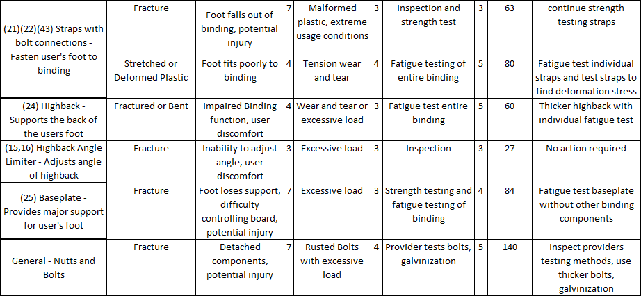
Through failure mode analysis shown in Appendix B, we determine that even though our board is made up of two parts, it is still less of an issue than the bindings. The highest risk priority number (RPN) for our board is less than many RPN’s from our original study on the bindings. Though failures involving fracture of the board are serious, they are very rare. The titanium rods in our board are even stronger than the original board. The highest RPN comes from failure of the board halves. If the material holding the fixed side of the rods are too thin and experience a lot of wear and tear, the rods are a bit more likely to rip through the board under extreme loading conditions. This is still very unlikely, though it could be severe. More likely failure is from the bonds between the fixed end of the rod and the resin breaking and the rods wiggling their way out of the board; however, this is not severe because as long as the board is closed the rods cannot fall out this way. A final potential issue is the latch breaking. The pins embedded in the board could come loose under too much force, but this also would not be too severe. They original board did not have a very high RPN, so our goal was not to reduce risk.
Mechanical Analysis
Original Snowboard
We began by conducting static and vibrational experiments on the regular snowboard, so that we would be able to match the properties of the foldable snowboard to that of the regular snowboard.
We focused our static analysis on the bending of the board, as in normal use the board mainly experiences bending. We did a static bending experiment on two commercial snowboards, which allowed us to find a value of Young’s modulus of 6.48 GPa for the first board, and 9.48 GPa for the second board.
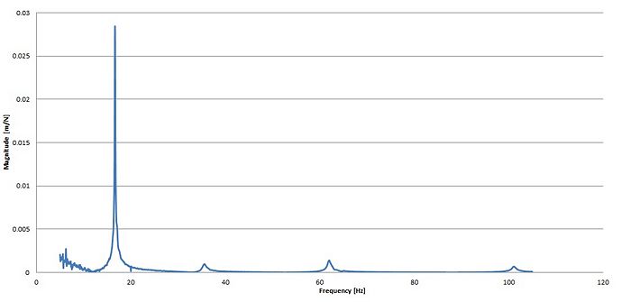
We then performed a dynamic analysis of the snowboard. We began with a vibrational experiment in which we suspended the board to the ceiling by two bungee cords attached to the bindings mounts. By exciting the board with an impulse hammer and recording the vibrations with an accelerometer, we were able to find the natural frequencies and damping coefficients of the first few modes. The first three natural frequencies are 17, 35 and 61 Hz. The frequency response function that we obtained is in Fig 5.1.
We then made a CAD model of the second board and performed a finite element frequency analysis. By matching the natural frequencies of the FEA with the above experimental results, we found a value of the board stiffness of 8.76GPa, which is very close to the value found in the static experiment. This shows that our computer model of the original snowboard is accurate.
Prototype
We then had to make an important design decision regarding the shape of the material that would connect structurally the two halves. We had two design choices for the folding mechanism, one was a plate design, the other one was a tube design. Our main goal is that the static and dynamic properties of our foldable snowboard match the ones of the regular board.
We began by calculating the dimensions that we would need for both the plate and the tube designs, in order to have the same bending stiffness as the original board. We solved the beam bending equations for the maximum deflection under a given load applied to the center for both designs, and set that deflection equal to the deflection that we would get under the same load for a regular snowboard. The calculations can be found in Appendix D.
From these equations we were able to find the following equation, which is the relation needed between the length, height (or diameter) and Young’s modulus of the plate/tube, such that the stiffness in bending of the foldable design is equal to that of a regular snowboard.
Where L is the half-length of the snowboard, l is the length of the plate/tube, d is the space between the center screws, E and I are the properties of the plate/tube, Eb and Ib are those of the board.
Where L is the half-length of the snowboard, l is the length of the plate/tube, d is the space between the center screws, E and I are the properties of the plate/tube, Eb and Ib are those of the board.
Using this equation we were able to optimize the mass of the plate/tube by varying length and height/diameter of the board, thus finding ideal values for these parameters that both satisfy the above equation and give a minimal mass. We did the optimization for the two designs and using three different materials. The results are in Appendix D.
The results show that the tubes have a much lower mass than the plate design for a same bending stiffness. The tube length also remains inferior to the distance between the bindings of the board. We compared the tubes at an outer diameter of 5.50 cm as this is the minimum tolerable value for polypropylene, but if wood or aluminum was chosen we would pick a lower outer diameter. This would give a slightly higher mass, but would take up less space. Based on these results, we decided to choose the rod design.
To decide upon a material for the rods between polypropylene, wood, alumunium, steel and titanium, we decided to calculate the force that we would need to apply in the middle of the snowboard for plastic deformation to appear, the board being mounted on both ends. For each material, we used the dimensions given by the optimization. The calculations and results are in Appendix D. The polypropylene and titanium rods have the highest resistance, which means that they can sustain the highest applied force before plastic deformation appears. We consequently chose to use polypropylene for our prototype, and titanium for our final design.
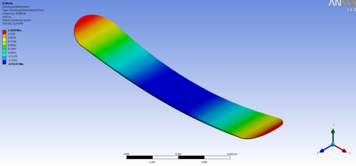
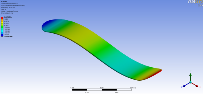
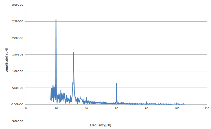
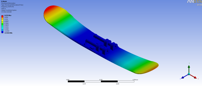
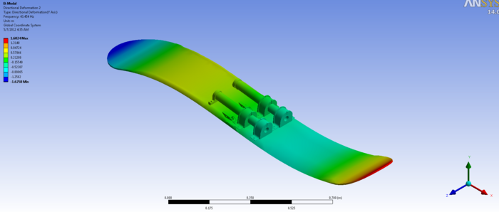
After the prototype was built, the same dynamics testing was performed as on the original snowboard. Figure 5.3 below presents the results of this testing. We found natural frequencies close to the ones of the original board, of 19, 32 and 60 Hz. We also did a FEA on the CAD of the prototype, and found the same natural frequencies in the FEA as we did in the experimental testing. The FEA results are in Figure 5.4.
Final Design
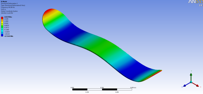
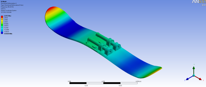
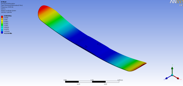
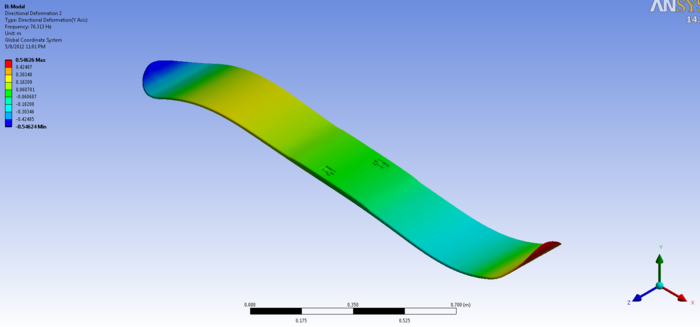
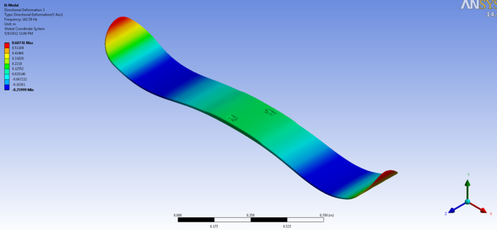
Figure 5.5 below show the FEA results for the production version of our board using the model previously developed with the prototype board.
Prototype Documentation
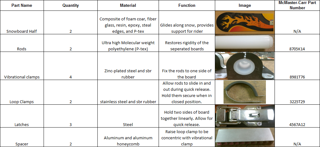
Our final prototype demonstrates our snowboards ability to split into two parts, and then to be reassembled while maintaining its structure. A list of parts used in the prototype can be found in Appendix C. Our prototype also demonstrates the quick release ability of our final design. The user can quickly open the three latches and separate the two halves of the board. They can then slide the two halves back together – inserting the rods into the loop holders – and close the three latches. There are too purposes for this prototype. One is to demonstrate the quick release mechanism. The other purpose was to verify that dynamic properties of the board could be maintained with a two part board held together with appropriately chosen rods. For this, we used an accelerometer to conduct a dynamic test on the original board and the assembled prototype. The results of this testing has already been discussed. It verifies that using rods set into the board in our final design will result in a functional snowboard. A number of key differences exist between our prototype and our final design. In our final design the snowboard is manufactured from scratch, where as in our prototype we modified an existing snowboard. Therefore the main difference is that in our final design the rods are set into the board – something we could not do in the prototype. In addition, there are eight rods in the final design as opposed to two in the prototype. These rods are significantly smaller in diameter and made of titanium. Another noticeable difference is the thickness of the center of the board in the final design. In order to house the rods, the board must become thicker in the center.
Since our rods will be set into the board, the need for the vibration clamp and loop clamp is eliminated. Instead, on the fixed end the rods are embedded in a layer of resin inside the foam core and fiberglass sections of the board. Opposite the fixed rods on the other half of the board, hollow tubes are embedded in the same way. The rods slide smoothly into the tubes when the two halves of the board come together.
The board was simply cut in half for the prototype; however, for the final design the interface between the two board halves is “z” shaped. One side of each board half is longer than the other. This type of interface ensures that no pole or edge will ever line up perfectly between the two sections of the board. Each half of the board has four of the rods embedded on its longer side. The shorter side holds the hollow tubes. Since the two halves of the board are identical, only one manufacturing setup is necessary and each individual half of the board is replaceable. The final difference between our prototype and our final design for mass-production is with regard to the latches. The latches on our prototype were store bought and intended to be attached to a surface. For our final design our latches are incorporated as a part of our board and are uniquely designed. For each latch, two pins are depressed into the board (one on each half) and used as attachment points for the latch.
In general, our prototype weighed about 11.17 pounds without the bindings. The final design will weigh less than that because the rods are smaller and the holders are removed. For reference a typical snowboard weighs about five to seven pounds. Many potential users expressed interest in trying our prototype and more were interested in trying out our final design. Some expressed concern over the weight, but most of the added mass is in the center of the board where the riders mass dominates, and the inertial moments are not affected much. Most feedback was positive.
Design Process
Our teams main line of communication was through a Google group that we all became a part of in the beginning of the year. We used this to schedule meeting and establish roles. In meetings we discussed progress and problems we had, as well as the tasks ahead. While team members had certain roles they were more focused on, each members role was pervasive and most parts of the project were done together. Chris led the team in finite element analysis. Evan led the CAD of the prototype and the original board to be analyzed. Phil led the CAD of the final design. Eric and Saviz did optimization and led in the testing of the prototype and original board. This project is almost ready for production. Production and testing of the final design as a prototype and then mass production are the remaining steps.
Team Member Roles
Saviz Mowlavi - Team leader
Evan Walden - Prototype lead
Chris Tomaszewski - Finite Element Lead
Phil Brown - Final CAD Lead
Erik Ringvold - Optimization of Design lead
Appendices
Appendix A: Bill of Materials with CAD Drawings
Appendix B: FMEA
B1: Final Design
Note: Design Controls are recommended
B2: Original Product
Appendix C: Prototype Parts
Appendix D: Mechanical Analysis
Beam bending calculations: Image:Beam bending.pdf
Optimization results: Image:Optimization.pdf
Breaking calculations: Image:Breaking.pdf

