Tire changing kit
From DDL Wiki
Contents |
Executive Summary
The emergency tire changing process has multiple oppurtunites for improvment and innovation. In this first phase the main component of the process, the car-jack was analyzed. The car-jack being the most crucial tool required in the tire changing process this was a good starting point for identifying area where improvement could be used. Initial steps of analyzing the product included indentifying customer needs, usage studies and identifying mechanical functions by method of product dissection.
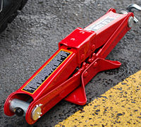
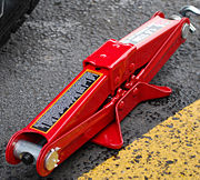
The basic functionality of a jack stems from rotation of a horizontal threaded screw by a crank arm, which causes a vertical translation of the jack head due to an inward rotation of the pivot arms. This vertical translation inturn raises the vehicle.
From the product dissection, we observed that the jack was a fairly simple design that was assembled from just 16 individual components and just a single layer of assembly. The jack was evaluating using standard categories for DFM and DFA. Results indicated the product was well though out, using a nearly minimum number or parts and materials. From the DFA analyis it was noted that assembly could be simplfied by using standard fasteners instead of rivets. However there is a possibility that this choice was deliberate to avoid end-user attempt at disassembly.
FMEA analysis was also performed to help identify any possible failures of the product. This analysis showed the most of the failure modes resulted from deliberate/ accidental misuse or poor maintenance. In the cases of misuse, both property damage and/or injury could result.
Design for Environment (DFE) analysis revealed that the cost of Carbon Dioxide emissions during production and use were miniscule compared to the price of the product. Furthermore, since the entire mechanism is made entirely of steel, it can be melted down and re-used. In conclusion for the DFE, a Carbon Dioxide tax would have little effect on the price, use, and production methods for the product.
Stakeholders and Associated Needs
The primary post-production stakeholders include the users, retailers, freight carriers, and businesses.
| User | Retailer | Transporter | Business |
|---|---|---|---|
* Vehicle Owner
| * Compact
| * Compact
| * Compact
|
Usage Study
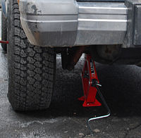
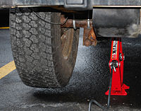
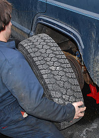
The basic process for use of the product is documented below. Please note that the product is considered a “universal” product and not vehicle specific. The universality introduces subtle differences in the process depending on the vehicle being serviced.
Usage Notes
- Jack handle is small (Both Lever and overall length)
- Requires user to be partially under vehicle while lifting
- Makes turning difficult for smaller or older operators
- Does not have the ability to lift from the "pinch-Rail" of the vehicle.
Mechanical Function of the assembly
Motion Observations
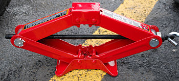
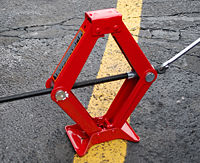
The assembly is basically a 7 bar linkage. Due to the symmetry of the device it can be broken down into two 4-bar linkages that are working together. As the drive screw is rotated the distance between the two large pins is shortened. As a result the parallel distance between the drive screw and the baseplate and the drive screw and the top plate is increased thus raising the jack.
Below the jack is depicted in three stages of lifting. In the first image the jack is fully lowered and the screw is fully with drawn. In the second photo the jack is partially raised. Note how the angles made between the arms and the drive screw are symmetric throughout the device. Finally, in the 3rd photo the jack is nearly at full height. Symmetry is maintained. Not is this state the drive extends highly from one side of the device.
Motion Analysis
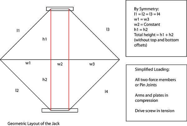
By dividing the mechanism into sections and applying symmetry it is relatively easy to analyze the motion of the jack. The figure below shows the layout of the jack in a partially raised position, with the labels for the length of each major component. Applying symmetry the relations on the right were generated. . Accordingly in the lower legend is a description of the simplified loading of the device discovered through inspection.
It can be shown that the height of the jack (h1 +h2) is related directly to the length of the portion of the screw between the large pins (w1 + w2 + w3). As the screw is turned this distance is reduced. Using the triangles enclosed by the arm, screw, and red-line the value of h1 can be determined by:
![]() Where w1 is half the total length of the rod between the large pins less the constant distance w2, and l1 is the fixed length of the moving arm.
Where w1 is half the total length of the rod between the large pins less the constant distance w2, and l1 is the fixed length of the moving arm.
Special Features
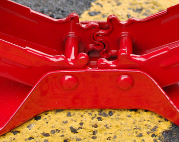
In order to maintain parallelism between the top plate and base plate gear teeth are designed into the upper and lower arms. These teeth maintain the symmetry of the angle produced by the arms. In doing so they force the upper and lower plates to remain parallel with drive screw. Actual loading on the teeth is not easily determined as it depends greatly on how the jack is being loaded
A detail view of the gear teeth is below:
Exploded View and Bill of Materials
Main Components
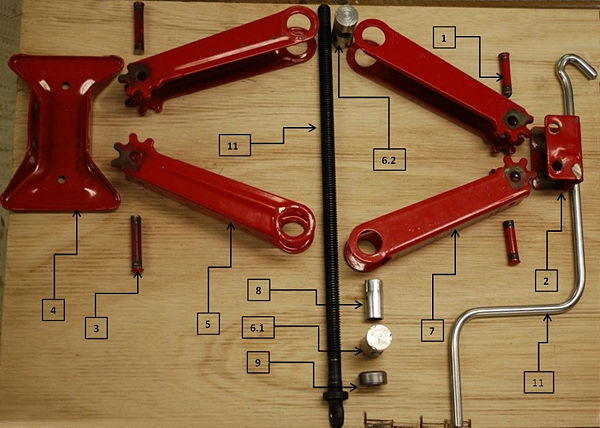
As can be seen in the table below, the standard Car-Jack contains 11 unique parts and 16 total parts(including screws and pins), all of which are made out of steel of cast steel. Most of the parts have been designed to maximize strength while decreasing weight and cost. We were able to completely disassemble the mechanism to its component level, since the entire mechanism was manufactured using a single layer of assembly.
Assembly: Exploded View
Design For Manufacture and Assembly (DFMA)
Product dissection revealed that the manufacturer took both manufacture and assembly into consideration when designing the product. It is clear that the manufacturer attempted to minimize production cost and assembly time. A summary of the design considerations and areas of improvement is included below. (Observations are marked as obs, recommendations are marked as rec)
Design for Manufacture (DFM)
- Minimize Part Count
- obs- The Product already uses the minimum number of parts to complete the task.
- Standardize Components
- rec- Use off the shelf locknut instead of aluminum collar on drive screw
- Commonize Product Line
- obs- The “Big Red” line of scissor jacks comes in multiple load ratings. As such each model has to be sized for the desired load. Despite this need for different strength parts, the similarity allows personnel to be trained on one unified design.
- Standardize Design Features
- obs- The design of the jack is symmetric. As a result many of the parts come in pair simplifying manufacture
- rec- Instead of different width upper and lower arms, use the same width and interleave the assembly (might cause stability issues)
- Keep Designs Simple
- obs- In accordance with the minimum number of components, the design does not include any frivolous features that would complicate the design.
- Multifunctional Parts
- obs- The design as is does not include any multifunctional parts.
- rec- Possible area for improvement. A good example would be to use the jack handle as a lug wrench.
- Ease of Fabrication
- obs- The majority of parts are stamped steel components. This is a cost effective method for high volume production
- Avoid Tight Tolerances
- obs- None of the components are high tolerance
- obs- Rivets expand to fit holes when compressed
- Minimize Secondary and Finishing Operations
- obs- Due to the steel construction most components are painted to avoid rusting
- Take Advantage of Special Process Properties
- obs- No Special Processes are used in construction
- Other
- obs- Arm length selected to achieve desired max lift height
- obs- Bottom and Top plate sized for stability
Design for Assembly (DFA)
- Minimize Part Count
- obs- The Product already uses the minimum number of parts to complete the task.
- Minimize Assembly Surface
- obs- All assembly surfaces are sliding surfaces. As a result there is already a minimum assembly surface
- Use Subassemblies
- obs- Design includes only one assembly
- Mistake-Proof
- obs- Fastener and components are sized to only fit together in one arrangement
- Minimize Fasteners
- obs- The design uses only the number of fasteners require to provided necessary motion
- Minimize Handling
- obs- Assembly is likely put together in one step using an assembly jig.
- Minimize Assembly Directions
- obs- Assembly is already simplified
- Provide Unobstructed Access
- rec- Replace Rivets with shoulder bolts and lock nuts for serviceability (This might have been deliberately avoided by manufacturer)
- Maximize Assembly Compliance
- rec- Chamfer Teeth for easy assembly
Failure Mode and Effect Analysis (FMEA)
In the failure mode and effect analysis (FMEA) of the scissor jack we first identified possible components of the scissor jack that could fail. Then we analyzed the how the failure occurs, the effects of the failure, and causes of the failure. Each type of failure to a different component was given a rating for severity of failure (S), occurence of failure (O), and detectibility of failure (D). The risk priority number (RPN) was calculated by multiplying the three ratings. This risk priority number allowed us to determine which part of the scissor jack was most likely to fail and where we should spend our time trying to improve this product.
| Item and Function | Failure Mode | Effects of Failure | S | Causes of Failure | O | Design Controls | D | RPN | Recommended Actions |
|---|---|---|---|---|---|---|---|---|---|
| overloading | deformation of frame, failure of threads on dry rod due to abrasive wear | inoperable due to deformation or threads ruined | 9 | external leverage enabling lifting overweight. Overloading after raised | 3 | valve caps. If overload - visual indicator. Load gauge. Or limit useability in high load conditions with thread pitch | 8 | 216 | limit useablility in high load conditions or jack designed to deform upon to high of a load |
| base not level | car falls off or jack collapses | danger to user - jack deformation | 6 | car tilted - jack collapses. | 4 | Base that can be adjusted or swivel for unlevel ground | 5 | 120 | Base that can be adjusted to unlevel ground |
| incorrect placement | car falls off or jack collapses | danger to car and/or user | 4 | Car on slope - car falls off / possible deformation | 4 | operation instructions on jack | 5 | 120 | operation instructions on jack |
| bearing | binding | unable to crank | 5 | dirt, water freezing | 2 | sealing / protecting bearing from environment, or enabling maintenance | 5 | 50 | sealing/protecting bearing from environment |
| piercing tire with rod | piercing of tire | unable to use tire | 3 | user placing scissor jack in the wrong manner | 3 | having a dull cap on rod to make it harder to pierce tire or signal light to indicate rod hitting tire | 4 | 36 | indicator light when rod is hitting an object |
As you can see from the table, the three failures with the highest risk priority number was overloading, base not being level, and incorrect positioning of the scissor jack. All three of these failures could cause damage to the scissor jack, car, or user.
The failure due to overloading is the major failure of this product and could be caused prior to or after using the scissor jack. This could cause damage to the jack, car, or user. One idea of fixing this problem is having the jack deform on purpose or not allowing the user to crank the jack at a certain load.
Design For Environment (DFE)
Design for Environment (DFE) is an analysis of how a CO2 tax would impact the cost of production or use of the scissor jack. In our analysis we will take into consideration the entire life cycle of the jack, aka a life cycle analysis (LCA). We will consider the material extraction, production, use, end of life, and transportation of the product. As a painted steel tool, our material extraction would entail coal mining, iron ore mining, and paint manufacturing. For production, the material would then have to be smelted into steel sheets and then crafted into the scissor jack. For this entire process we have chosen the hand tool sector on eiolca.net. We chose this sector because it analyzes non-powered hand and edge tools – a description that best matched our product. We also looked at the Detailed Item Output from the 2002 Benchmark Input-Output Accounts on bea.gov in order to confirm that the hand tool sector includes tools similar to that of a scissor jack. Since there are items such as “mechanic’s service tools” as well as other tools made out of steel, we can conclude that the hand tool sector is an accurate description of our product.
Production
Greenhouse Gasses
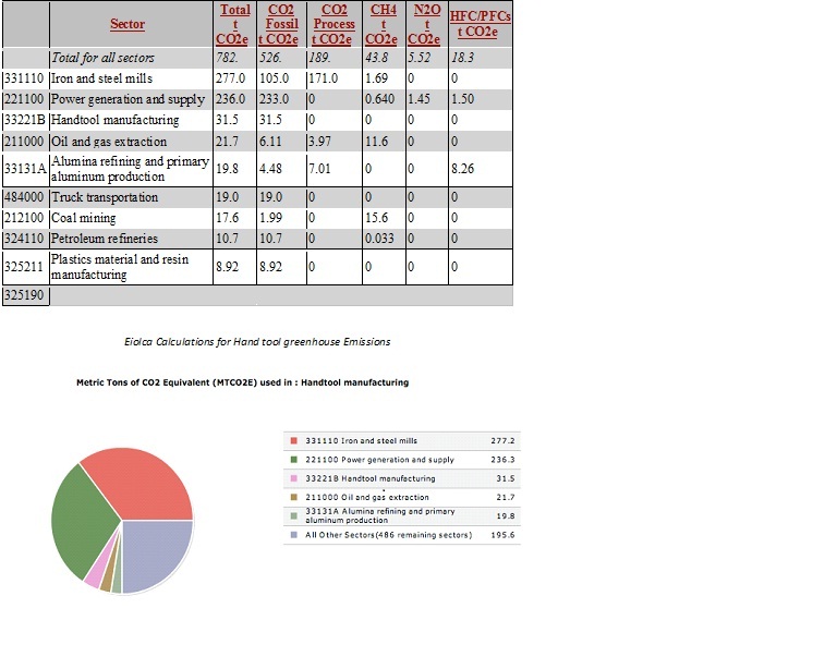
In 2002, for every one million dollars spent in retail value on scissor jacks, 782 metric tons of Carbon Dioxide are emitted into the atmosphere. Scaling this down to units of metrics tons per jack, we see that the creation of one jack emits approximately 0.023 metric tons of Carbon Dioxide. The emission emitted from iron and steel mills and power generation supply contribute the vast majority of the Carbon Dioxide release (66%). If a Carbon Dioxide tax of $30 per metric ton of CO2 is enacted, a total of $23, 450 would be taxed per million dollars sold. This equates to 70 cents per scissor jack, or approximately 2%. This cost is noticeable, but would have a small implication on the cost of the product.
Economic Activity
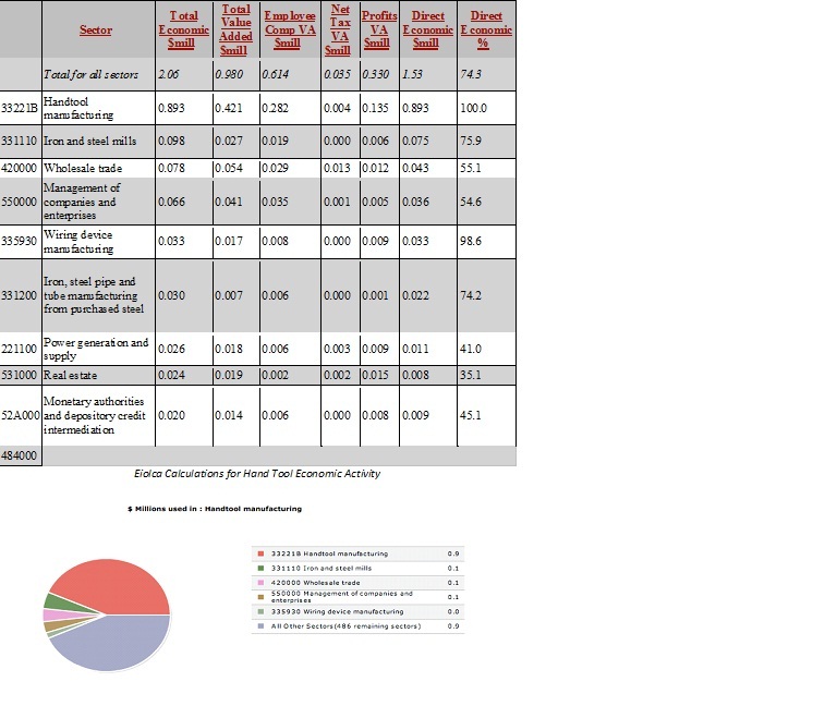
In 2002, for every one million dollars spent in retail value on scissor jacks, 2.06 million must be spent during the complete economic supply chain. We can also note that 74.3% of the economic cost goes directly towards the manufacturing of the product.
Use
Our product does not require assembly, power, or additional lubrication to use. It is ready-to-go when taken out of the box. Because of its simplicity, the only emissions generated from its use would be the effect of driving with the additional weight of the product in the car. Our product weighs approximately 6.9 lbs. Using the data available on “fueleconomy.gov,” an additional 100 lbs in a vehicle can reduce the gas mileage by a maximum of 2%. 7 lbs equates to approximately 0.14% max reduction in gas mileage. Using the information on http://www.epa.gov/oms/consumer/f00013.htm, we find that the average pollution per person is approximately 11,500 pounds of Carbon Dioxide per year. Assuming that gas mileage has a direct effect on the emission of Carbon Dioxide, we calculate that the extra weight of a scissor jack causes an emission of 16.1 pounds of Carbon Dioxide per year. Compared with the 0.023 metric tons (50.7 lbs) of carbon dioxide generated for the creation of this product, the added weight of once scissor jack makes a noticeable difference.
If we assume that an individual maintains the amount of driving approximately above for 50 years and that a scissor jack will work properly for the 50 years, we see that an extra scissor jack will cause an extra 805 lbs of Carbon Dioxide to be emitted over the course of the driver’s lifetime. This Equates to .365 metric tons per jack and with a $30 CO2 tax, an individual will pay an extra $10.95 in Carbon Dioxide emissions. This price is negligible compared to the cost of gas for the car over 50 years.
End of Life
The jack is made entirely of steel and can be melted down and re-used.
Conclusions
We have concluded that a Carbon Dioxide tax would have a small impact on the life cycle of the scissor jack. The scissor jack is already compact, and has the minimum number parts necessary to function correctly. The only areas where we can reduce the amount of emissions from Production of the jack are to either: 1) make the jack handle into a lug wrench so that we can minimize parts; or 2) make a smaller version of the jack that can only be used for compact cars. Both of these options would reduce the material amount. The first option has no downside, but with the second option – we would have to be careful that consumer did not misread the box and attempt to use the smaller jack on a vehicle that is too heavy to support.
References
www.fueleconomy.gov http://www.epa.gov/oms/consumer/f00013.htm, http://www.eiolca.net
Team Member Roles
Phase I team roles (Subject to change in subsequent phases)
- Team Leader - Justin Dawber
- DFMA Leader - Shrey Aggarwal
- FMEA Leader - John Boyle
- DFE Leader - Jon Licht
