Umbrella check-out system
From DDL Wiki
Contents |
Executive Summary
By evaluating people's feelings towards umbrellas, we were able to identify shortcomings with the current model of umbrella usage. At the moment, everyone is expected to carry a personal umbrella. Compact umbrellas, while easy to carry, are prone to failure and in most cases do not provide adequate coverage. Full-sized umbrellas and golf umbrellas are too large and bulky for daily use. Market research showed these two commonly recurring complaints. People want large umbrellas when it's raining but do not want to carry them once they get inside. Our solution to this problem is an umbrella distribution system. Users can pick up an umbrella when leaving a building and deposit it at the entrance of the next building that they go to.
This system provides many advantages. There is no need to carry umbrellas inside, reducing floor dripping and wet umbrella storage. Full-sized umbrellas are used in the units. These are more durable and provide better coverage than collapsible umbrellas.
Each unit is small and modular, with a capacity of approximately 12 umbrellas. An integrated circuit handles an input and output gate to control the flow of umbrellas. An umbrella is fed when users swipe their ID card. The system records which umbrellas have been checked out by users. The users then have up to ten days to return the umbrellas to any unit. Units sync wirelessly to the campus network to update information.
The outer shell can be made from three pieces of stamped steel for ease of manufacturability and assembly. All circuitry can be integrated onto a single board, and the circuit board can connect to all of the hardware via a single standard 15-pin connector.
A full implementation on Carnegie Mellon's campus would take approximately 160 units. At an estimated cost of $300 per unit, this would cost approximately $50,000. Spread out among Carnegie Mellon's student body population, the per-user cost would be $6-7, which was found during user testing to be an acceptable amount. Total production volume is estimated at 2000 units up front, with an additional 400 units per year for upkeep.
Design
Objectives and Opportunities
Umbrellas are an object that many people have complaints about. They are either too small, too flimsy, or just inconvenient to carry around. For our design solution, we decided to develop a way to make umbrellas more convenient to use.
Market Analysis
Umbrellas have been utilized and evolved with human beings to provide a sense of safety and protection from the elements. Umbrellas keep us dry during the rain, offer mild wind resistance, and even protect us from the sun by providing shade on hot days. However, users are not satisfied with the current stage of umbrellas and still look for more evolution and improvement of the products. To identify major customer needs regarding the umbrella usage, market analysis and user studies related to the product were conducted by getting feedback of the actual users for different types of umbrellas.
Selected Responses
Among the answers to survey questions asked during the user studies, the following responses are selected.
- "I want the size of my umbrella to be adjustable, so I can get into my car with an umbrella when it rains. In that way, I don't need to get wet when I get in."
- "I don't want to lose my umbrella in any case since I usually lose one and get a new one before it breaks off."
- "I want my umbrella to be smaller, so it's easier to carry around."
Identified Customer Needs
Based on the observations and answers to the survey questions, our team has identified four major customer needs:
- Umbrellas should be hard to lose
- Umbrellas should be easy to open and close
- Umbrellas need to be portable
- Umbrellas should provide adequate coverage
Pictures

This picture shows how users often rest umbrellas on their shoulders instead of holding them vertically.
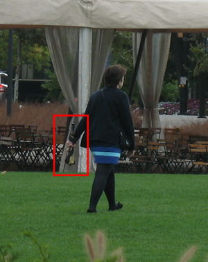
This picture shows how users often carry umbrellas at their center of gravity because it makes it more comfortable to hold.
Target Market Identification
The potential customers for the umbrella check-out system would be administrative managers of universities or business campuses with large amounts of intra-building movement and rainy weather. In the places where the weather is fickle, people tend to forget to bring their umbrellas if it is not raining in the morning. Or, people who don't forget to bring their umbrellas in the morning tend to carry around their umbrellas all day long, but they end up not getting much utilization from the umbrellas. In the worse case, some of them just end up losing their umbrellas even before they get to utilize them. This situation causes big issue of inconvenience for the umbrella users. To solve this kind of issue, administrative managers of facilities complexes could consider installing the umbrella check-out system on their buildings.
Concept Design
Overview and Usage
This concept is a system of umbrella distribution units. Each unit is small and battery powered.
Users swipe an ID card at the lower end of the unit. This dispenses one umbrella through the turnstile. The umbrella's ID number is logged in the user's account information. The user then walks to their next location, depositing the umbrella into a unit at the new location. A reader at the new location notes the umbrella coming in, and removes that umbrella from the user's account.
The system will know when a user has checked out an umbrella and not returned it. Users can be charged a penalty if umbrellas are not returned with a given timeframe.
Physical Design
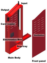
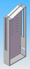
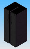
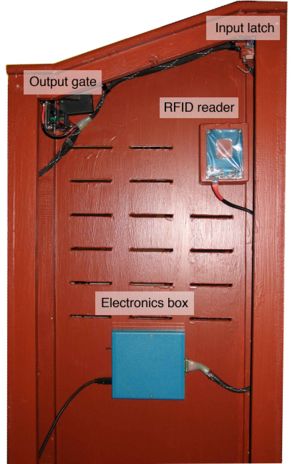
Each unit consists of four major components: the shell, the electronics subsystem, the output turnstile, and the input gate.
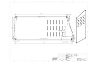
The shell is what encompasses all of the internals. It provides physical support for everything else.
The electronics subsystem is the heart of the unit. It consists of a microcontroller, a card scanner, and an RFID reader. The microcontroller provides the logic to control the other systems. The card scanner allows the system to identify users, and the RFID reader allows the system to identify umbrellas.
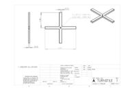
The output turnstile is what dispenses umbrellas to the user. It is a small motor attached to a worm drive gearbox. On the output shaft of the worm drive are four turnstile arms. An infrared break-beam sensor provides feedback about the turnstile's position.
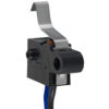
The input gate is a one-way gate, allowing umbrellas to be returned to the system. A limit switch provides a signal when the gate is closed.
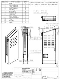
Table 1: Bill of Materials
Distribution and Placement
Units should be placed at major doorways around the institution. While it is difficult to quantify what exactly a major doorway is, it should be fairly self-evident to people that frequent the facility.
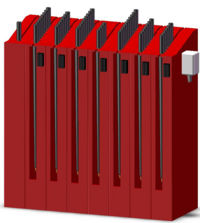
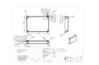
The umbrella dispenser's small footprint at only 6" by 18" (similar to the footprint of a shoebox) allows it to be placed almost anywhere in a hallway. Even a short row of dispensers does not occupy much floorspace. Dispensers can be placed at the sides of hallways, or, if the hallway is sufficiently wide, along the center to create a traffic divider. Units are battery powered and do not need to be located near a plug.
Dispensers that are not used often should be relocated to areas with higher than expected umbrella usage or traffic. The units will fit on any standard sized hand cart for easy transportation. As seen in our analysis, determining the distribution of units before placement is difficult.
For our sample implementation on the campus of Carnegie Mellon University, we estimate that approximately 160 dispensers will be needed. The doorways needing the most dispensers are those located in Doherty Hall, the University Center, and Porter Hall.
Failure Modes
| Subsystem | Failure Mode | Effects of Failure | Severity | Causes of Failure | O | Design Controls | D | RPN | Recommended actions | Responsibility |
| Outer Shell | Rust | Decreased aesthetics | 4 | Coating failure | 3 | Process control | 3 | 36 | Visual check of surface | Manufacturer |
| Surface damage | 4 | Finish hardness | 2 | 32 | Visual inspection | Manufacturer | ||||
| Warping | Umbrella jam | 5 | Abuse | 3 | 2 | 30 | Customer | |||
| Output turnstile | Jamming | Umbrella not fed | 5 | Low power | 5 | Battery indicator | 2 | 50 | Low power indicator | Customer |
| Motor failure | 3 | Motor diagnostics | 5 | 75 | Customer | |||||
| Breakage | Umbrella feeding failure | 5 | Abuse | 4 | Visual inspection | 2 | 40 | Customer | ||
| Photogate failure | Turnstile freespins | 5 | Dirty sensor | 3 | 1 | 18 | Visual check | Customer | ||
| Input latch | Sticking | Umbrellas removed through top | 5 | High friction | 3 | Tolerance check | 4 | 60 | Maintenance | Customer |
| Breakage | Latch no longer functional | 5 | Abuse | 2 | Visual inspection | 2 | 24 | Inspection | Customer | |
| Electronics | RFID failure | Umbrella not counted | 3 | Power issues | 3 | Low voltage indicator | 2 | 18 | Inspection | Customer |
| Bad RFID tag | 2 | Pre-testing | 4 | 24 | Inspection | Manufacturer | ||||
| Card reader failure | Umbrella not dispensed | 3 | Bad/dirty card | 2 | 3 | 18 | Customer | |||
| Microswitch failure | RFID not activated | 5 | Worn out switch | 2 | 3 | 30 | Inspection | Customer | ||
| Battery failure | Unit not functional | 7 | Low battery | 3 | Low voltage indicator | 2 | 42 | Visual check | Customer | |
| Moisture | Damage to IC: System not functional | 7 | Housing failure | 3 | 6 | 126 | Ensure box seal | Manufacturer |
As seen from our FMEA, the highest RPN rating is failure of the electronics due to moisture because of its difficulty to detect and potential to take down the entire system. Special care will have to be taken to ensure that the box is completely sealed against moisture. The input latch and output gate should also be stiff and robust enough to prevent both accidental and abuse breakage.
Manufacturing and Production
Process
Our final product incorporates several DFMA principles designed to improve manufacturability and decrease product cost.
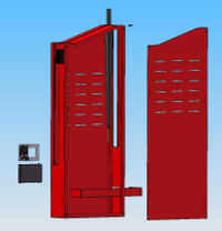
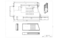
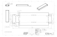
The outer shell, access panel, and drip tray are manufactured out of a common gauge of steel sheet metal, and use low energy forming processes such as punching and bending to create their overall shape. This method of manufacturing was chosen due to the speed and ease of which the singularly stamped parts can be made into the final shape. The punching and bending can also be completed either by automated machine or by a manual operator. This means that the volume of production can be scaled to various levels while still remaining cost effective. Once formed, the design of the shell allows for easy access to the interior of the unit, improving the ease of assembly with the other components.
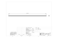
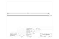
The interior support pieces are manufactured out of a common size of steel tubing, such that the pieces are just cut to length without additional forming needs. The supports are easily spot welded to the shell, and the welding could be done automatically or manually.
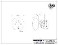
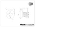
The access panel is secured to the shell using 4 stainless steel screws. The use of screws, in place of snap fits or rivets, does increase assembly time. However, this increase is warranted due to the fact that it allows our unit to be easily disassembled for maintenance.
The housing for our integrated circuity is injection molded using ABS in order to protect our circuitry from water and contaminants by creating a hermetic seal between parts of the casing. While the injection molding process is expensive for initial tooling, the per part cost is small and our units are reusable as housings for related circuitry. The housing type is common enough that it could even be sourced to an outside company that sells similar enough housings for our purposes.
Remaining components are sourced from various outside vendors, and are attached to each other using either screws or snap fits. Due to the design of the outer shell, as well as component placement inside the shell, all components can be easily accessed and assembled.
Volume
From our analysis, we estimate that we would need the capacity to store approximately 2000 umbrellas around Carnegie Mellon's campus. Given that our dispenser stores about 12 umbrellas per unit, we would need about 160 units for campus.
There are approximately 2500 four-year universities in the U.S., with an average enrollment of about 4400 students each. This is about half of Carnegie Mellon's undergraduate and graduate enrollment total. If the number of dispensers is directly related to the number of students, the average university will need 80 units.
If we can interest just 1% of four-year universities at the start, our estimated production volume will be 2000 units up front. Additional units or replacement parts may need to be purchased later. At an average lifespan of 5 years, an additional 400 units will need to be produced annually.
Prototype History
Our design went through a number of iterations. Here are the major design prototypes.
First Prototype
Our initial prototype was designed to be a small modular unit with a simple design and low part count. The flat sides of the device allow multiple units to be placed next to each other for an umbrella distribution with multiple locations to take out and return umbrellas. The body of the device was built with MDF (Medium Density fiberboard) wood material and painted red. The ramp on the top of the device, which was made of low-friction teflon material, moves umbrellas quickly from the receiving end to the dispensing end with no additional mechanical input from the system. Keeping the number of parts in the device low increases the reliability of the device. The only places where the umbrellas need to be actively dealt with by the system are the input and output chutes. For the input chute, there was a latch attached to a torsional spring to make sure that umbrellas cannot taken out from the receiving end once they are returned. Also, for the output chute, a turnstile was implemented to make sure that one umbrella is taken out at a time.

Second Prototype
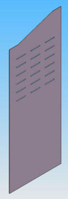
The second prototype was a modified version of the first prototype. The major change in the second prototype compared to the first design is that an electrical system was implemented into the device. The electronic system is activated by users who swipe their ID card which tells the device to dispense an umbrella. The device dispenses umbrellas by rotating a turnstile alowing only one umbrella to be dispensed at a time. The motion of the motor is controlled by a microcontroller which rotates the turnstile by approximately 90 degrees. Also, ventilation holes are located on the sides of the device to facilitate drying of wet umbrellas through free convection. The input chute of the device was machined down to have a ramp inorder to make it easier for users to return their umbrellas back to the system after use. A removable drip tray was added on the bottom of the device to collect the water runoff from wet umbrellas while they are stored inside the device. For the second prototype, the actual umbrellas, specially chosen for the prototype, were used to test the function of the device.
Final prototype
For our final prototype, a new device was designed and constructed. A new body of the device was built using MDF wood inorder to accomidate a smaller footprint. The shell is also designed to have a access panel on the side to provide easier access to the inside of the device for the purpose of design for maintainability. The major difference between our second and final prototypes is a more sophisticated electrical system implemented on the device to achieve the features of a fully automated umbrella dispensing system and to incorperate an RFID card reader to track the actual flow of umbrella usage. Also, the dispensing system incorperates a gearbox with a worm drive to power the turnstile. As users swipe their ID cards, the system gets activated and the motor turns on until the turnstile hits a switch to turn off the motor after rotating 90 degrees. As an umbrella is checked out by a users, the system associates that umbrella thth the users. The users can later return their umbrellas by putting them into the input chute of the device, which activates an RFID reader to read the RFID tags on the umbrella being returned. The RFID reader does not turn on unless a umbrella actually passes the single way latch, which prevents the potential of scanning an umbrella without returning it and allows the system to save power. The returned umbrellas are recognized by the system as having been returned and ready to be taken out by other users.
Production differences
For the production model, the body will be made of stamped steel instead of wood to improve durability both due to wear and moisture, manufacturability of the design, and minimization of waste in the manufacturing process. Steel box section will be welded inside the shell to improve the robustness of the unit. The drip tray of the device is made of stamped steel, spot welded, and designed to be easier to open for maintaince personel. The structure of the unit will consist of five unique parts: a long support, a short support, a driptray, and an access panel which can all be assembled using a spot-welding process. The switch to turn off the motor at the output chute is replaced with a beam sensor to obtain absolute 90 degree angle rotation of the turnstile and to dispense one umbrella at a time. This also prevents a possible failure mode of umbrellas getting jammed during the dispensing process.
Analysis
Comparison of Alternatives
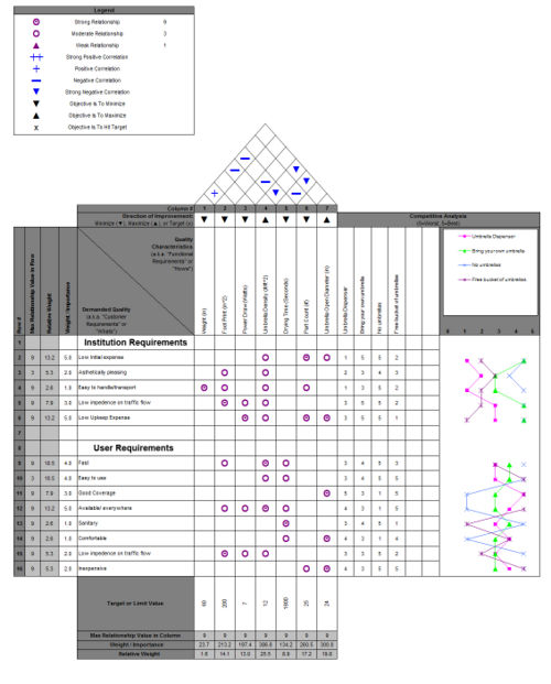
In order to compare our system to current market alternatives, we used QFD to better delineate how our product might gain market advantage over our competitors in satisfying customer needs. Since our umbrella checkout system has no direct competitor, we chose to benchmark our design against the possible alternatives that customers may choose in place of using our system. This included bringing your own umbrella from home, not using an umbrella at all, and placing free buckets of free umbrellas for people to take.
After conducting QFD, we came to the conclusion that our system, while not excelling at satisfying the needs of either institutions or users, provides a good compromise between the needs of both groups. For institutions, the preferred option is for people to either bring their own umbrellas or use no umbrellas at all, since it represents the least amount of cost and effort on the part of the institution. Users, on the other hand, would rather have a free system of umbrellas that they can just take and use freely. Unfortunately, the solution that is optimal for one group is directly opposed to the solution for the other group. Our solution creates a workable compromise that comfortably, though sub-optimally, meets the needs of both groups.
Summary of Advantages Offered by Our System:
Our umbrella distribution system offers several advantages over individual users carrying umbrellas. The improvements fall into the areas of safety and convenience.
Safety was considered from many angles in the development of the system. Control over the umbrella drying ensures that no umbrella will remain damp for too long, which could occur if the umbrella was shoved into a poorly-ventilated backpack. Users will also be in contact with the umbrella only during use, which minimizes potential exposure to microbes. More people will be using each single umbrella, but waterless hand sanitizer units, located at the end of each row of dispensers, will prevent germs from transferring from users' hands to the umbrellas.
There are other advantages that comes from not having users carry around umbrellas unnecessarily. Because each unit is located near a doorway, umbrellas will not be carried wet through the hallways, resulting in fewer wet, slick hallways. Similar effects will be seen in rooms, with less moisture on the floors where damp umbrellas are generally tossed.
The main reason that this system is attractive is its convenience. Users will no longer have to carry flimsy collapsible umbrellas, or large full-sized umbrellas. Umbrellas will be available when needed, and unobtrusive when not needed. There will be no more worrying or scrambling after forgetting an umbrella at home. Full-sized, durable umbrellas are used, and bulk purchase decreases the per-unit cost.
Quantitative Analysis: Traffic Study
Motivations
The physical construction of our device is relatively simple. It contains few components, and those components are already well-developed and commonly used. The size of the device is constrained by the umbrellas, and device weight is not a large concern since it will be stationary. Given this, we did not feel that a strictly mechanical analysis would provide us the insight that we need to develop a complete solution. In addition to the design of the hardware, the issue of implementing the system had to be addressed. This is where we chose to focus our analysis.
The largest issue of implementation is determining where to place the units, and how many modular units to put at each location. Traffic flow into and out of each doorway is the major determinant of this, so we decided to find out what the traffic flow was like as a function of time at the major doorways on campus. By determining the flow rate and difference in number of umbrellas at each location we can determine the number of umbrellas needed at each location for a given time, and the speed at which these umbrellas need to dry in order to be ready for reuse.
Methods
Two methods were used to investigate traffic flow at the major doorways. The first was to model our campus using a Markov simulation. This is model that uses probabilities of users moving from one location to another to estimate overall traffic flux around campus.
The second method was sitting by doorways and counting people going into and out of each doorway. Data was logged, time stamped, and analyzed later.
Findings
Our largest learning from these analyses is that it is very difficult to model traffic flow. Personally counting everyone moving through a given doorway is time-intensive. Modeling traffic flow is faster, but the number of assumptions necessary to produce a functional model may invalidate the results. Even if we could accurately model traffic flow on campus for a rainy day, the existence of the checkout system could alter traffic patterns significantly.
From observing people moving in and out of doorways, we got an order of magnitude estimation of necessary umbrella capacity at the major locations. Our analysis shows that it will take a capacity of approximately 200 to 300 umbrellas at the major doorways on campus.
The simplest solution to solve the modeling and estimation inaccuracies is to overpopulate the system initially, and then move units around as needed to meet demand. A full analysis to get a better estimate of traffic flow would be to difficult, if not impossible, to achieve, and would require many hours to realize. Overpopulation of units is simple and fast.
User Testing
After completing our final prototype, we observed how other users interacted with the unit, and discussed their thoughts about the distribution system as a whole. Most people were very enthusiastic about the idea of not having to carry an umbrella around. One person said that his company leaves umbrellas floating around for use, and that they always end up taken or missing.
Our prototype worked well. The dimensions were comfortable for everyone, except for one six year old who was too small to use it. Usage was intuitive, with a single location to take and receive umbrellas. Most people's concerns dealt with failure. Concerns were expressed about durability, theft, and electronic failure. From our user testing, we can see that we must make our design robust enough to reduce apprehensiveness.
Conclusions
To summarize, our main findings about this design are:
- Estimated production volume of 2000 units up front, plus 400 units per year.
- Each unit would cost approximately $300 to manufacture and have a lifespan of about 5 years.
- Each umbrella in the system would cost $3 to $4, including the RFID tag.
- The fastest - and easiest - way to implement this system is to overpopulate the environment with dispensers initially, and adjust as needed.
- An example implementation at Carnegie Mellon would involve about 160 dispensers.
- This gives a capacity of about 2000 umbrellas.
- The total cost would be approximately $50,000.
- The per-user cost would be $6 to $7, an acceptable amount according to user feedback.
- Users were very receptive to the idea of an umbrella distribution system.
- Two different business models can be pursued: a flat-out sale of units, and a lease type program.
Design Process
The challenges of a design project of this scope requires a well thought out design process and methodology. This is particularly true for group projects with more than 1-2 people. This section details how our group went about the design of our system, as well as some of the tools and methods we used to streamline the design process.
Methodology
Our fundamental design methodology was based on the idea that we can make design decisions more efficiently and accurately together than we can apart. This fundamental philosophy guided a large majority of how we conducted our work. For almost all major design decisions, we met as a group and conducted thorough discussion until consensus was reached. These actions resulted in our designation of a design "war room", so to speak, where all of our major decision making was conducted. We ensured that this place was well equipped for our needs (whiteboards, projector, prototyping materials), such that we could discuss and analyze all important design issues without interruption.
Once design decisions were made, tasks were split up equally among team members such that each of us could work independently towards at unified set of goals and deadlines. One of the key tools that made this independent collaboration possible was our use of an online file sharing service called Dropbox, which allowed us to seamlessly share version controlled files across multiple computers with ease. The use of this service allowed us to keep track of when files were updated and acted as a communal pool into which we could place all of our files and resources. This practice made it easy and fast to coordinate our tasks at independent times and locations. Despite this service, all major decision making and coordination of tasks was conducted in our "war room" so that we could quickly ensure that everyone was on the same page.
Timeline
In order to meet the deadlines laid down by our client, our team assembled a Gantt chart to help us prioritize our tasks and deliverables. This Gantt chart is reproduced below:
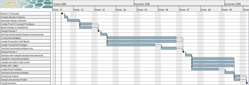
In addition to the Gantt chart, weekly meetings with our client representatives (Professor Jeremy Michalek and Norman Shiau) helped us maintain steady progress.
Team Member Roles
Ben Berkowitz: Prototype work, bill of materials and manufacturing concerns, traffic flow analysis, component design and assembly, writing, market research, user testing
Michael Cushman: Prototype work, MATLAB modeling, traffic flow analysis, component design and assembly, writing, market research, user testing
Mark Fuge: Prototype work, microcontroller programming, traffic flow analysis, component design, writing, market research, user testing
Changho Oh: Prototype work, artwork, failure modes, component design, writing, market research, user testing
Remaining Steps to Market
Were we to take this product to market, the following components of the design would need to be finalized:
Business Model: Our design concept forms the foundation for an entirely new business model. Our product could either be sold as separate units, or as a lease/rental system. A lease/rental system would provide us with substantially better control over the reuse or recycling of the system, as well as being more profitable as a business venture.
Product Families: Our product design lends itself well to extensions of product families. Most locations will need more than one standalone unit. Sets of units can be consolidated into a single shell with a single control unit and card swipe, but multiple tracks for umbrellas. This could potentially save on costs, however, further investigation would be necessary to develop the full product family.
