Rotating tie rack
From DDL Wiki
(→Rotating Tie Rack Inputs and Outputs) |
|||
| Line 1: | Line 1: | ||
=Executive Summary= | =Executive Summary= | ||
| - | =Product | + | =Product Study= |
As part of the project, our group has selected a rotating tie rack to analyze, and attempt to apply its rotation mechanism to a rotating shoe rack | As part of the project, our group has selected a rotating tie rack to analyze, and attempt to apply its rotation mechanism to a rotating shoe rack | ||
| Line 21: | Line 21: | ||
*The speed of rotation cannot be controlled. There is no way to speed up the rotation to reach a tie that you know is right at the back of the closet faster. | *The speed of rotation cannot be controlled. There is no way to speed up the rotation to reach a tie that you know is right at the back of the closet faster. | ||
| - | == | + | ==Inputs and Outputs== |
There are many factors affecting the use and production of this product. | There are many factors affecting the use and production of this product. | ||
| Line 32: | Line 32: | ||
*Energy output : Rotation of rack, light from bulb | *Energy output : Rotation of rack, light from bulb | ||
| - | =Rotating Tie Rack Use Scenarios= | + | ==Rotating Tie Rack Use Scenarios== |
The way the rack is used may vary from customer to customer. The conventional use is described in a section above, but other uses are also possible: | The way the rack is used may vary from customer to customer. The conventional use is described in a section above, but other uses are also possible: | ||
| Line 45: | Line 45: | ||
Age or disability is most likely not a problem for consumers, because if hung in the proper place in closet it can be used by consumres of all heights, weight ratios, ages, and abilities. | Age or disability is most likely not a problem for consumers, because if hung in the proper place in closet it can be used by consumres of all heights, weight ratios, ages, and abilities. | ||
| + | |||
| + | ==Other Stakeholders== | ||
| + | Aside from the consumers, there are others who are affected by the engineering and manufacturing of the product. Those individuals include, but are not limited to, the workers in the assembly line, the supervising engineers, and the people designing the manufacturing equipment. | ||
| + | |||
| + | *Common problems for the assembly workers could be: | ||
| + | **Assembling motor: grease on hands | ||
| + | **Parts not snapping together properly | ||
| + | **Soldering circuit board and wires could cause plastic to melt | ||
| Line 142: | Line 150: | ||
|| 026 || Lubricant || 1 || Facilitates movement in the gear train || - || 2 || N/A || Purchased part | || 026 || Lubricant || 1 || Facilitates movement in the gear train || - || 2 || N/A || Purchased part | ||
|} | |} | ||
| - | |||
| - | |||
| - | |||
| - | |||
| - | |||
| - | |||
| - | |||
| - | |||
| - | |||
| - | |||
Revision as of 12:08, 9 February 2007
Contents |
Executive Summary
Product Study
As part of the project, our group has selected a rotating tie rack to analyze, and attempt to apply its rotation mechanism to a rotating shoe rack
Function
This product is a space saving and organizational device. It is most likely placed in a consumers closet, and used to hang ties and belts. It can hold upto 64 ties and 8 belts. The rotating tie-rack allows the consumer to utilize to full depth of the closet that is normally wasted when using a conventional tie rack. The since the rotating mechanism provides easy access to all ties, even those that were initially far back in the closet.
Conventional Consumer Use
The product is fairly simple to use. The user begins by removing the item from its packaging. The user first inserts four C batteries into the battery compartment, and attaches the battery cover (004). The user then takes the top assembly (003) and places it over the closet rod, then placing the rest of the assembly beneath it, and fastening the two together. For some people, this is a difficult process. The top cover (011) is difficult to attach to the top assembly, and can get stuck, leaving the product partially assembled, and difficult to pull back apart. Once the product is assembled on the rod, the user must use the locking screws (002) to lock the tie rack in place on the rod. The tie rack can be attached to any rod that is smaller than the hole created when the top cover is attached to the top assembly. The locking screws can even hold a rod that is much smaller than the hole firmly in place.
Finally, once the product is assembled, it is ready to be used. Ties are hung on each hanger on the rotating belt (007), which is done easiest by letting the rack rotate while hanging a tie on each hanger. Once the ties are all hung, one can also hang belts on the belt hangers (003) hanging from the bottom of the assembly. These are difficult to acces however, because the ties are in the line of sight and the line of access. To remove a tie from the rack, one must push one of two buttons, left or right, to decide which way the belt will rotate. When the user pushes one of these buttons, a light turns on, spotlighting whichever tie is right in front of the rack. This is a good feature,since most closets tend to be dark, but the light itself does not have its own switch, meaning that the user cannot turn it off if it is undesired, which may be the case since it will drain the batteries faster.
Difficulties
- Assembly is difficult: top assembly and top cover are difficult to attach.
- Hanging ties is difficult: rack rotates too quickly-- must be constantly stopped while hanging ties.
- Access to belts is difficult: ties are in the way.
- Light turns on automatically when tie rack is in use, and cannot be turned off by user. This drains the battery more quickly.
- User must push the opposite button as already pushed to stop the rack. For example, if the user is pushing the right button to rotate the rack, he or she must push the left button to stop it, BUT, if the user pushes the left button too hard, the rack will begin spinning in the opposite direction.
- The speed of rotation cannot be controlled. There is no way to speed up the rotation to reach a tie that you know is right at the back of the closet faster.
Inputs and Outputs
There are many factors affecting the use and production of this product.
The inputs are:
- Energy input : 3 V (from C type batteries in series)
- Information input: User presses switch and selects direction of rotation
The outputs are:
- Energy output : Rotation of rack, light from bulb
Rotating Tie Rack Use Scenarios
The way the rack is used may vary from customer to customer. The conventional use is described in a section above, but other uses are also possible:
- Use by a man to hang ties
- Use by a woman to hang ties
- Use by a man to hang ties and belts
- Use by a woman to hang ties and belts
- Use by a man to hang belts only
- Use by a woman to hang belts only
- All of the above could be placed inside or outside of closet
Age or disability is most likely not a problem for consumers, because if hung in the proper place in closet it can be used by consumres of all heights, weight ratios, ages, and abilities.
Other Stakeholders
Aside from the consumers, there are others who are affected by the engineering and manufacturing of the product. Those individuals include, but are not limited to, the workers in the assembly line, the supervising engineers, and the people designing the manufacturing equipment.
- Common problems for the assembly workers could be:
- Assembling motor: grease on hands
- Parts not snapping together properly
- Soldering circuit board and wires could cause plastic to melt
Rotating Tie Rack Dissection
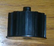
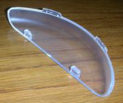
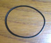
The product was dissassembled to analyze each individual part of it. Each part was weighed, measured and described, and its purpose was thoroughly analyzed.
The following are the components of the assembly:
| Part # | Part Name | QTY | Function | Materials | Mass (g) | Dimensions (cm) | Manufacturing Process | Images |
|---|---|---|---|---|---|---|---|---|
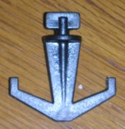
| 001 | Belt hook | 4 + 4 extra | Attach to notches in middle of Belt cover to provide a place to hang belts | Plastic (1); black, hard | 2 | 3.6 x 1.355 x 0.3 | Injection molding | |
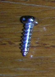
| 002 | Locking screws | 2 | Lock Top assembly into place over closet rod | - | 12 | Cap: 2.4 dia x 1.0
Screw: 0.5 dia x 3.3 | Purchased part | |
| 003 | Top assembly | 1 | Attaches tie rack to closet rod; there is an arrow to indicate the direction which it slides in | Plastic (2); black, hard, finished surface | 26 | 11.57 x 4.5 x 1.9 | Injection molding | |
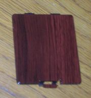
| 004 | Battery cover | 1 | Protects batteries from the environment and keeps them in place | Plastic (2) | 9 | 6.9 x 6.12 x 0.2 | Injection molding | |
| 005 | Screws | 6+7+2 |
| - | 0.5 | 0.4 dia x 1.18 | Purchased part | |
| 006 | Belt cover | 1 | Holds Rotating belt, Belt gear and Belt rotator to tie rack | Plastic (2) | 45 | 29.5 x 4.6 x 0.9 | Injection molding | |
| 007 | Rotating belt | 1 |
| Plastic (3); black, flexible | 55 | 36.5 x 12.5 x 2.41 | Injection molding | |
| 008 | Belt gear | 1 |
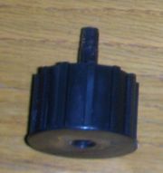
| Plastic (4); black, hard | 14 | 4 dia x 2 x 2.05 (pin) | Injection molding | |
| 009 | Belt rotator | 1 | Holds other end of belt in place and allows for rotation | Plastic (4) | 14 | 4 dia x 2 x 1.7 (pin) | Injection molding | |
| 010 | Light cover | 1 | Protects Light bulb | Plastic (5); clear, hard | 8 | 3.1 x 10.35 x 1.4 | Injection molding | |
| 011 | Top cover | 1 | Encloses the mechanism that causes rotation | Plastic (2) | 150 | 37.95 x 13.9 x 4.8 | Injection molding | |
| 012 | Gear belt | 1 | Attaches Magnetic motor to Gear driver | - | 0.5 | 6 circ x 0.2 | Purchased part | |
| 013 | Gear cap | 4 | Holds gears and Gear driver on Pins | - | 0.1 | 0.25 ID x 0.3 OD | Purchased part | |
| 014 | Gear driver | 1 | Attaches Magnetic motor to gear train | Nylon | 2 | 2.3 dia x 1.0 | Injection molding | |
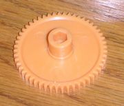
| 015 | Gear, clear | 2 | Decreases speed provided by the Magnetic motor and increases torque | Nylon 6 | 3 | 4.3 dia x 0.8 | Injection molding | |
| 016 | Gear, yellow | 1 | Decreases speed provided by the motor and increases torque | Nylon 5 | 3 | 4.3 dia x 1.2, hexagonal core | Injection molding | |
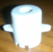
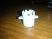
| 017 | Motor cover | 1 | Protects Magnetic motor | Plastic (6); cream, hard | 6 | 2.7 dia x 3.2 | Injection molding | |
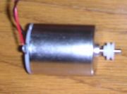
| 018 | Magnetic motor | 1 |
| - | 136 | 2.4 dia x 3.1 | Purchased part | |
| 019 | Spring | 2 |
| - | 3 | 0.9 dia x 2.4, unloaded | Purchased part | |
| 020 | Circuit board (with wires) | 1 |
| - | 5 | 3.0 x 3.85 | Purchased part; main unit of subassembly | |
| 021 | Light bulb | 1 |
| - | 2 | 0.9 dia x 0.7 | Purchased part | |
| 022 | Switch | 1 | Allows switching the direction of rotation and activates Light bulb | Plastic (7); cream, hard | 7 | 6.8 x 3.2 x 0.8 | Injection molding | |
| 023 | Bottom cover | 1 | Encloses mechanisms for rotation | Plastic (2) | 162 | 37.95 x 13.9 x 3.3 | Injection Molding | |
| 024 | Pin | 3 | Holds gear fixed onto Bottom cover | - | 1 | 0.2 dia x 1.4 (yellow gear), x 1.85 (white gears) | Purchased part | |
| 025 | Battery end plate | 2 |
| - | 4 | 4.6 x 1.65 | Purchased part | |
| 026 | Lubricant | 1 | Facilitates movement in the gear train | - | 2 | N/A | Purchased part |
