The customer’s primary need is to cool a room by circulating air. More air circulation provides greater air movement and cooling potential. The fan’s noise level is a concern of the customer. Quiet operation, with little to no vibrations is preferred. The customer must also be able to adjust the fan’s rotational speed to best suit the surroundings. This allows for quieter, lower energy, operation when maximum air circulation is unnecessary. Another necessity is the ability to vary the direction of where air is being. This includes altering the vertical orientation as well as providing horizontal oscillation. The fan should also be safe for the user. This involves shielding the fan blades, while still allowing air to pass through. This shielding prevents objects and body parts from coming in contact with the blades. Fans are generally only used during warm times of the year. As a result they must be easy to move and store while not in use.
An oscillating fan cools an area using forced convection thus increasing heat transfer. This is accomplished by spinning three plastic blades which circulates air in the desired direction. The blades are spun by an AC brushless motor, which is powered from a standard 120V wall outlet. The motor’s rotational speed can be adjusted by the user using a circular knob. The fan is also capable of horizontal oscillation. The user starts this movement by pushing a button at the top of the fan casing. This engages a gear train which spins a small plastic linkage. This linkage is connected to an aluminum bar which is attached to the casing. This simple mechanism translates circular motion to oscillatory horizontal motion. The gear train is powered by the same motor and shaft that spin the blades, thus requiring no additional motor.
First, the customer must plug the fan into a 120V wall socket. Once plugged in, the user may turn the fan on by rotating the knob from the off setting. The user may adjust the fan's speed to low, medium or high, by rotating the knob to the desired setting. The user can set the fan to oscillate by pressing down on the rear switch. The oscillation allows the fan to cool multiple locations. The user can stop the fan from oscillating by simply pulling up the rear switch. The consumer may also change the vertical direction of the fan by using a Phillips screwdriver on the screw connecting the fan to the shaft. The user must loosen the screw, aim the fan in the desired direction, and then tighten the screw. For storage, the consumer must turn the knob to the off setting, unplug the fan from the 120V wall socket, wrap the power cord around the head of the fan, disassemble the fan head and stand, and place the pieces in the storage unit.
| Part # | Part name | QTY | Function | Materials | Manufacturing Process | Picture
|
| 001 | Front Fan Cover | 1 |
- Protect the user's body parts
- Protects fan blades
- Aesthetics
| ?? | Merging of Extruded Parts | 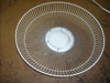
|
| 002 | Threaded Cap for Blades | 1 |
- Holds blade unit in place
- Left handed threading to keep it from loosening
| Plastic | Injection Molding | 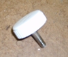
|
| 003 | Blade Unit | 1 |
| Plastic | Injection Molding | 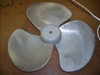
|
| 004 | Set Screw | 1 |
| Steel | Extrusion | 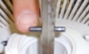
|
| 005 | Rear Plate Fastener | 1 |
| Plastic | Injection Molding | 
|
| 006 | Rear Fan Cover | 1 |
- Protect the user's body parts
- Protects fan blades
- Aesthetics
| ?? | Merging of Extruded Parts | 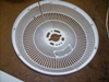
|
| 007 | Motor Front Cover | 1 |
| ?? | Cast | 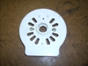
|
| 008 | Swivel Adjustment Knob | 1 |
- Adjusts DOF's of fan position
| Plastic/Steel | Injection Molding/Extrusion | 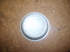
|
| 009 | Nut for Swivel Adjustment Knob | 1 |
- Fastens bolt of adjustment knob
| Steel | Stamped | 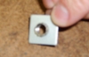
|
| 010 | Fan Head Coupling | 1 |
- Attaches fan head to stand
| Plastic/Steel | Injection Molding/Extrusion | 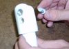
|
| 011 | Speed Selection Knob | 1 |
- Turns on power
- Selects speed of fan
- Interfaces with switch
| Plastic | Injection Molding | 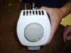
|
| 012 | Switch | 1 |
- Turns on power
- Selects speed of fan
- Interfaces with speed selection knob
| Plastic/Copper | Injection Molding/Stamped | 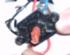
|
| 013 | Motor Housing | 1 |
- Covers
- Motor
- Shaft
- Electrical Components
| Plastic | Injection Molding | 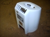
|
| 014 | Capacitor | 1 |
- Stores electrical potential energy
| Plastic/Other | N/A | 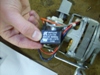
|
| 015 | Electrical Wire | 7 |
- Connects electric components
| Plastic/Copper | Drawn | 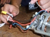
|
| 016 | Oscillation Gear Casing | 1 |
- Holds the gears that control oscillation
| ?? | Cast | 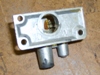
|
| 017 | Gear Casing Cap | 1 |
| Plastic | Injection Molding | 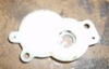
|
| 018 | Oscillation Control Knob | 1 |
| Plastic | Injection Molding | 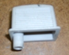
|
| 019 | Transmission Gear | 1 |
- Transfers rotation from shaft to gear 1
| Plastic | Injection Molding | [[Image:]]
|
| 020 | Small Ball Bearing | 1 |
- Prevents free motion of transmission gear
| Steel | Cast | 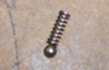
|
| 021 | Small Spring | 1 |
- Prevents free motion of transmission gear
| Steel | Extrusion |
|
| 022 | Gear 1 | 1 |
- Transfers rotation from transmission gear to gear 2
| Plastic | Molded | [[Image:]]
|
| 023 | Gear 2 | 1 |
- Transfers rotation from gear 2 to plastic shaft
| Plastic | Injection Molding | [[Image:]]
|
| 024 | Plastic Shaft and Oscillation Linkage | 1 |
- Interfaces gear 2
- Transfers rotation to oscillation linkage
| Plastic | Injection Molding | [[Image:]]
|
| 025 | Oscillation Linkage | 1 |
- Transfers rotational motion to angular motion of fan oscillation
| ?? | Cast | 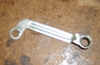
|
| 026 | Shaft | 1 |
- Transmits motor power to fan and oscillation gearing
| Stainless Steel | Extrusion | [[Image:]]
|
| 027 | Permanent Magnet | 1 |
- Uses electromagnetic force to rotate shaft
| Ferric Material | Coiled Wire | 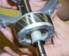
|
| 028 | Rear Shaft Support and Bearing | 1 |
- Supports and allows smooth rotation of shaft
| ?? | Cast | [[Image:]]
|
| 029 | Front Shaft Support and Bearing | 1 |
- Supports and allows smooth rotation of shaft
| ?? | Cast | [[Image:]]
|
| 030 | AC Motor Block | 1 |
- Holds motor coils and electromagnets
| Steel | Cast/Rolled | 
|
| 031 | AC Motor Coils | 1 |
- Proide alternating current to electromagnets
| Copper | Drawn | 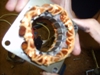
|
| 032 | Wire Holder | 1 |
- Keeps wires in place and out of harm
| Plastic | Injection Molding | 
|
| 033 | Power Cable | 1 |
- Transfers power from source to fan
| Plastic/Steel | Molded/Stampled | 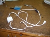
|
| 034 | Screws | 22 |
- Fastens various parts together
| Iron/Steel | Extrusion/Rolled | 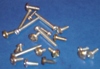
|
| 035 | Bolts | 1 |
| Iron/Steel | Extrustion/Rolled | 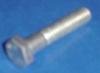
|
| 036 | Washers | 4 |
- Provides surface contact area for nuts
| Iron | Stamped/Bent | 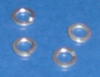
|
| 037 | Nut | 1 |
- Interfaces with bolt to fasten
| Iron | Cast | 
|
| 038 | Wire Coupling | 1 |
- Connects and protects 2 wire ends
| Plastic | Injection Molding | 
|
| Item and Function | Failure Mode | Effects of Failure | S | Causes of Failure | O | Design Controls | D | RPN | Recommended Action | Responsibility and Deadline | Actions Taken | S | O | D | RPN
|
| Motor/Shaft
| Inhibited Rotation | Inefficient Operation | 5 | Debris (e.g. dust) in Fan | 4 | Run Under Extreme Dust and Debris Conditions | 2 | 40 | Filter, Accessibility for Cleaning, Better Protection of Rotating Parts | Motor Housing | - | 5 | 3 | 2 | 30
|
| Swivel Mount
| Nut Stripping, Plastic Fracture | Cannot Adjust Vertical Directoin Fan Cannot Effectively Circulate Air | 8 | Overtightening, Material Failure | 3 | Overtightened Screw, Force applied on Swivel Area | 1 | 24 | Use Torque Limited Fastening, Using Stronger Plastic | Swivel | - | 8 | 2 | 1 | 16
|
| Oscillation Button
| Dislocation of Button | Cannot Toggle Oscillation | 6 | Stripped Gear, Button Disengaged | 5 | Stronger Gears, Improved Connection | 2 | 60 | Fatigue Testing | Gears and Button | - | 6 | 3 | 2 | 36
|
| Blade Cover
| Inhibited Rotation, Blade Fracture | Complete Inoperable | 8 | Penetration of Cover | 4 | Penetrate Repeatedly | 1 | 32 | Warning Label, Redesign Cover | User | - | 8 | 3 | 1 | 24
|
| Shaft
| Non-concentric Rotation | Vibration and Noise | 5 | Broken Bearing, Unbalanced Weight, Shaft Non-Uniformity | 2 | Quality Control | 3 | 30 | Vibration Testing | Assembly | - | 5 | 1 | 3 | 15
|
| Electronics
| Short Circuit | Completely Inoperable | 8 | Exposure to Water | 3 | Water Exposure Testing | 2 | 48 | Waterproof Housing of Electronics | Housing | - | 8 | 1 | 2 | 16
|
Design for Environment
The environmental impact of a single oscillating fan may seem negligible. This seemingly innocent arbiter of consumer comfort provides "cool" circulated air in times of great heat, but could one's fan actually be adding to the problem of global warming? Then one must wonder if the release of greenhouse gases by fan manufactures is just a simple ploy to sell more of their product. Putting this circular logic aside for the moment, the environmental impact of oscillating fans will now be analyzed.
As a baseline for all calculations and data, all analysis will be done per million dollars of economic activity. According to NAICS data from 1997, the economic sector responsible for the manufacture of oscillating fans is 335211 Electric Housewares and Household Fan Manufacturing. Data about this and other sectors associated with it are compiled in the Economic Input-Output Life Cycle Assessment (EIO-LCA) database. This utility allows one to locate data and calculate various aspects of economic and environmental activity related to any economic sector. For sector 335211, the sector responsible for most economic activity is itself. This means that most of the money put into the production of fans (and more) is used by the fan producing industry. The other major sectors associated with the economic aspects of production are wholesale trade, management of companies and enterprises, Plastics plumbing fixtures and all other plastics products, and All other forging and stamping (each accountable for fractional amounts of the total capital of the sector).
A major environmental concern related to manufacturing any product is the amount of greenhouse gases and other air pollutants released into the atmosphere. According the the EIO-LCA database, the leading contributer of conventional air pollutants (SO2, NOx, CO, etc.) related to fan manufacture is power generation, producing over half of all pollutants (power used to create components, etc.). The next closest is the Electric Housewares and Household Fan Manufacturing sector. These two individually contribute the most relative to all other sectors, and it is the remaining 490 associated sectors that produce about 1/5 of the gases released. Totals for emissions are given as about 2 million tons of SO2, over 7 million tons of CO, and 1.6 million tons of NOx compounds, among others. Results for greenhouse gases (specifically CO2, CH4, CFC's, and N2O) are similar. Power generation produces roughly 1/3 of all CO2 release associated with the fan manufacture. Other large producers are truck transportation, steel mills, and of course, the fan manufacturing sector itself. About 600 million tons of CO2 are released for every million dollars of fans produced.
The largest single producer of toxic wastes related with the fan sector is itself, contributing about 1/5 of the several tons of toxic waste released per million dollars of product. Many of these releases are associated with the many plastic components used in fans. Not surprisingly, the plastics sector takes second place in this category. About half of all toxins released are related to most of the smaller sectors involved in production.
These environmental considerations have just taken the production of fans within this sector into account. The environmental impact of the use of the fans will now be considered. For this analysis, some estimations will be used. Taking an average price for a common household oscillating fan such as the one analyzed as $50.00, the total number of fans per million dollars is 20000. The average power consumed during normal use is about 40W. During peak fan use season (Summer, about 90 days)the average fan user likely uses the product for 3 hours a day. 40W * 3h * 90days * 20000fans = 216 million kWh of power consumed by fans. According to EIO-LCA data, the total amount of energy consumed in producing this amount of fans is about 0.5 million kWh.


