Ice cream maker
From DDL Wiki
| Line 58: | Line 58: | ||
|- | |- | ||
! 018 | ! 018 | ||
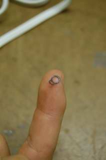
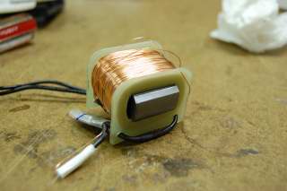
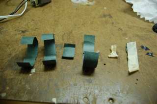
| - | | | + | | Motor Wrapping || Paper used to hold the motor copper coil in place and stop it from unraveling || || [[Image:IC motor wrapping.JPG]] |
|- | |- | ||
! 019 | ! 019 | ||
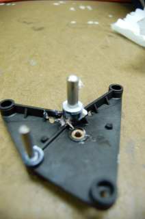
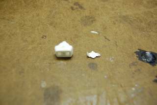
| - | | | + | | On/Off Switch Assembly || A mechanism used to open and close a circuit to allow users to manually stop and start the ice cream maker. || || [[Image:IC on off mechanism.JPG]][[Image:IC on off switch assembly.JPG]] |
|- | |- | ||
! 020 | ! 020 | ||
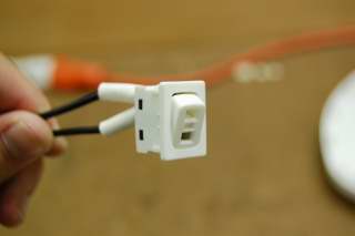
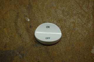
| - | | | + | | On/Off Switch || A user friendly switch that allows users to operate the On/Off switch assembly || || [[Image:IC on off switch.JPG]] |
|- | |- | ||
! 021 | ! 021 | ||
Revision as of 22:11, 23 September 2007
Contents |
Component List
Failure Mode and Effects Analysis
This chart shows the top failure modes of the ice cream/sorbet maker. This is a risk assessment of the major parts of the device and how each failure ranks on a priority list. The failures are recorded in a few categories, which are severity, occurrence, and detection. The severity of the failure is a value that represents how crucial this part or action is to the usage of the product. The occurrence represents how often the failure occurs per 10,000 products. The detection represents how easily the failure mode can be detected, either in the assembly line process or by the user. Here is our FMEA of our ice cream maker. After the table, some of the values will be explained in further detail.
| Item & Function | Failure Mode | Effects of Failure | S | Causes of Failure | O | Design Controls | D | RPN | Recommended Actions | Responsibility & Deadline | Actions Taken | S* | O* | D* | RPN* |
|---|---|---|---|---|---|---|---|---|---|---|---|---|---|---|---|
Motor
| Electrical failures: Motor may overheat and fail | Product will not mix the ice cream, and the product may not have good consistency. | 8 | Motor may overheat when the ice cream starts solidifying. The increased viscosity of the ice cream may add too much torque on the motor. | 6 | Testing with different types of ice cream and find the point when the load applied is too high | 5 | 240 | Find a controller that will turn off the motor once the torque applied to the motor gets too high | Motor Manufacturer | Integrate a current sensor into the design | 8 | 1 | 5 | 40 |
| Mechanical Failure: Gear train may strip | The rotation of the motor will not be transferred to the product | 8 | The increased friction in between the separate gears can cause the gears to strip | 2 | Testing the durability of the gears | 4 | 48 | Test different materials to find the most cost-effective solution | Gear Manufacturer | N/A | 8 | 2 | 4 | 48 | |
Mixing Arm
| Mixing arm breaks/fails | Contents of the bowl will not be properly mixed to form a consistent product. | 6 | The increased viscosity of the product may cause the mixing arm to break. | 3 | Test to see the breaking point of the mixing arm. | 1 | 18 | Test different materials to find the most cost-effective solution | Manufacturer | N/A | 6 | 3 | 1 | 18 |
Wiring
| Current does not get transferred from the power outlet to the motor | Motor will not rotate the bowl, so contents of bowl will not get mixed. | 8 | The increased viscosity of the product may cause the mixing arm to break. | 2 | Before final assembly of the product, test connection points to see if all wiring points are valid | 3 | 48 | Install a station in the assembly process to make sure that all wiring connections are good | Assemblerer | N/A | 8 | 2 | 3 | 48
|
Switch
| Switch does not allow current to pass through | Motor will not rotate the bowl, so contents of bowl will not get mixed. | 8 | The switch connection may not contact the part that is used to close the circuit | 2 | Test to see if connection points are durable after many clicks (turn on and off many times) | 3 | 48 | Test a switch for 1,000 times to see if the switch operates properly each time | Assemblerer | N/A | 8 | 2 | 3 | 48 |
The Failure Mode Effects and Analysis of this particular ice cream maker is based on the intended use of the maker. The rankings that were assigned represent how valuable each operation is to the overall function of the device. Although the design of the product is very simple, if these items were to fail, it would result in loss of function for the device.
The motor failure is classified as a severity of 8 because the criteria of 8 represents that "Item inoperable, with loss of primary function." Since the function of the ice cream maker is to mix the contents of the bowl, if the motor is not working, then the primary function of the device is lost. If the failure mode results in the loss of bowl rotation, then the product has lost its primary function and can no longer be used. The failure of the mixing arm was categorized as a 6 because the customer would have some dissatisfaction that the product can no longer be used properly, but the product could still be utilized to make ice cream. As you can see, the electrical failure of the motor has the highest RPN (Risk Priority Number), which means that this item and function has the highest probability of failing.
For the rest of the device, the occurrence and detection values are low because there is low complexity in the design. If there was a faulty connection, it would most likely be noticed in the assembly process. After reviewing customer reviews on amazon.com, we found that there were some customer complaints about motor failure and how ineffective the product was. Although this was not the best way to determine the occurrence and detection values, it was the best source of data that could be found on our product.
