Airsoft gun
From DDL Wiki
(→Assembly) |
(→Mechanical Analysis) |
||
| Line 1,069: | Line 1,069: | ||
= Mechanical Analysis = | = Mechanical Analysis = | ||
| + | Assumptions: | ||
| + | * No mechanical failure due to stresses in materials | ||
| + | * Small angles of rotation | ||
| + | * Friction is negligible | ||
| + | * Ideal spring loading | ||
| + | * Any other assumptions not listed here will be addressed when the issue arises | ||
| + | <br /> | ||
| + | The trigger assembly is composed of the trigger, a rotating lever, the piston release, and a mechanical safety. When the safety trigger and the primary trigger are pulled, the lever is pushed and rotates such that the piston release, which would have pressure being applied on it by the compressed spring in the bolt assembly, is released and is free to rotate. The vertical displacement of the right end of the lever must be 2mm downward for this release to occur, meaning the vertical displacement on the left side must be proportional to the lever arms. This ratio is 33mm/26mm = 1.27, meaning the displacement on the left must be 2.54mm. <br /> | ||
| + | [[Image:Airsoft_trigger_assembly.JPG|400px]] [[Image:Airsoft_trigger_pull.JPG|400px]]<br /><br /> | ||
| + | |||
| + | F<sub>T</sub> is the force between the trigger and the lever.<br /> | ||
| + | F<sub>frame</sub> is the force applied by the frame on the trigger. This keeps the trigger in equilibrium when there is not enough force to rotate the trigger. This value is zero when the trigger force passes some critical value. For these calculations, F<sub>frame</sub> = 0.<br /> | ||
| + | F<sub>1</sub> is the force applied by the trigger spring due to its compression. This spring is initially compressed 1mm.<br /> | ||
| + | F<sub>2</sub> is the force applied by the lever spring due to its compression. This spring is initially compressed 1mm.<br /> | ||
| + | F is the force applied at the middle of the curved portion of the trigger.<br /> | ||
| + | |||
| + | d<sub>T</sub> is the moment arm for F<sub>T</sub> about point O. d<sub>T</sub> = 33 mm<br /> | ||
| + | d<sub>t</sub> is the moment arm for F<sub>T</sub> about point P. d<sub>t</sub> = 7 mm<br /> | ||
| + | d<sub>1</sub> is the moment arm for F<sub>1</sub> about point P. d<sub>1</sub> = 10 mm<br /> | ||
| + | d<sub>2</sub> is the moment arm for F<sub>2</sub> about point O. d<sub>2</sub> = 20 mm<br /> | ||
| + | d<sub>frame</sub> is the moment arm for F<sub>frame</sub> about point O. d<sub>T</sub> = 13<br /> | ||
| + | d is the moment arm for F about point P. d = 25 mm<br /> | ||
| + | |||
| + | [[Image:Airsoft_trigger_forces.JPG|400px]] [[Image:Airsoft_force_analysis.JPG|400px]]<br /> | ||
| + | |||
| + | (insert calculations here) | ||
| + | |||
| + | <br /> | ||
| + | <br /> | ||
| + | From measured values, the force required to pull the trigger averaged out to 2.44N over ten trials. Also measured was the safety trigger pull, which averaged out to 0.44N over ten trials. This extra force is required to compress the spring inside the trigger that pushes on the safety trigger. Therefore, the actual force to pull the trigger is about 2.00N. | ||
= Links = | = Links = | ||
Revision as of 10:16, 24 September 2007
Contents |
Executive Summary
Our team has performed an extensive analysis of the Well's L96 Airsoft gun. The major topics that are examined are the customer needs, the system functionalities, a list of components, a preliminary analysis of the manufacturing process, environmental impact, and failure modes. With regards to the customer needs, we agreed that the purpose of an airsoft is for gaming and emulation purposes. A detailed account of the airsoft's functionality that includes every step from loading the magazine to the firing the BB through the barrel is noted in our report. A preliminary analysis of DFMA, FMEA, and DFE was also performed and the opportunities for improvements were highlighted. Finally, a mechanical analysis of the trigger assembly was done.
Product Study
In this section, we will examined the purpose, customer needs, functionality, input/output, user groups, and stakeholders other than or customer with regards to our product.
Purpose of Product
The purpose of an airsoft gun encompasses four categories: target practice, training, entertainment, and crime. Target practice and training are oftentimes similar practices. Airsoft guns are used as training tools by the military and the police as airsofts emulate the mechanisms of a real gun. Another popular use for airsofts is for entertainment purposes. Airsoft games are hosted regularly. Finally, airsofts may be used for crime. Since an airsoft gun resembles the actual gun that it is modeled after, once the orange cap is remove or painted metallic, airsoft guns may be mistaken for an actual gun and may be used for malicious intent. As a result, there are legislations regulating the use of airsoft guns in certain localities.
Customer Needs
Airsoft guns are built with two purposes in mind: functionality and emulation. Customers who buy the Well L96 are expecting an airsoft gun that behaves as a sniper rifle should. They will expect the gun to be powerful. Airsoft players with more powerful guns gain a tremendous distance advantage especially in outdoor arenas. An airsoft gun shooting with a muzzle velocity of 300 ft/s has an effective range of 150 ft while as guns that shoot 450 ft/s have effective ranges of over 200 ft. Of course, power is not the ultimate measure of a sniper rifle. A powerful gun is useless if it is not accurate. Customers will reasonably expect an airsoft sniper rifle to be accurate enough to hit a human sized targets at long distances (200 ft). In addition, customers need a durable gun. Durability involves building a gun that can handle environmental fatigue such as excessive sunshine, cold weather and rain. Since airsoft is a physical activity, it also means building a gun that will not break because a player mishandled his gun while doing a physical action such as diving for cover. Finally, the customer has safety concerns that must be addressed. Shooting an airsoft gun can be dangerous if it is misfired. The gun needs to have at least one kind safety mechanism.
Functionality aside, customers buy airsoft guns because of how well an airsoft gun emulates the actual gun. When owning the actual gun is too expensive or is illegal (i.e. Japan), customers buy airsoft guns as substitutes. The most important aspect of emulation is how well the airsoft gun resembles the actual gun. How heavy the airsoft gun is in comparison to the actual gun is also important.
Functionality
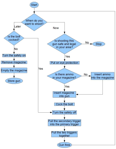
Firing this airsoft gun starts with loading BBs into the magazine. Oftentimes, a tool called a "speed loader" is used to aid in loading. As BBs are loaded, a spring in the magazine becomes compressed. The loaded magazine is then inserted into the bottom of the gun. When the magazine is inserted into the gun, the compressed spring pushes the BBs to the top of the magazine and releases a single BB into the gun's loading chamber every time it is cocked to be fired. With ammo ready, the shooter rotates and then pulls the bolt handle back. This pulls back the bolt which then compresses a spring. At a certain pull back distance, which is approximately as far back as the bolt can be pulled back, a knob inside the catches a notch on a piston inside the bolt. This knob will hold the compressed spring in place. The bolt is slid back forward and rotated back to its original position, after which, the gun is loaded and potentially ready to fire. The safety switch, which should be in the "safe" position when not in use, is then switched to the firing position by sliding it forward. The "safe" position is indicated by the safety switch covering the red dot marked on the side of the gun, and the firing position is indicated by a visible red dot. Then, the shooter will pull the trigger to shoot the gun. There is an additional safety on the trigger. Its appearance is a smaller trigger on the main trigger, and it must be pulled back with the main trigger in order for the gun to fire. Pulling the trigger releases the previously mentioned knob from standing up. It releases from the notch in the piston. As a result, the spring will expand quickly. This quick movement pushes the piston forward creating air pressure. The resulting air pressure enters the loading chamber through a nozzle and propels the BB through the barrel.
The Well L96 is classified in airsoft terminology as a spring gun.
Inputs and Outputs in Terms of Materials, Energy, and Information
- Material Input: magazine, BBs
- Material Output: BBs at high velocity
- Information Input: Direction of target
- Energy Input: Energy to cock barrel, energy to pull trigger
- Energy Outputs: Heat, noise
- Other Output: Pain
User Groups Who May Dave Different Needs
- Kids and adults
Airsoft guns are toys for kids; adults consider airsofts to be training/practice weapons.
- Left-handed and right-handed people
- People with different heights and different arm lengths
Guns are designed to be one-size-fit-all but different people like different lengths of stock and lengths of barrel.
- Indoor and outdoor play
If the airsoft is for indoor target practice, it does not need to be as durable and as rugged as an outdoor airsoft gun.
Other Stakeholders
Other entities that have an interest in airsoft guns include:
- Manufacturer of the airsoft guns
- Companies that product the original gun that the airsoft is modeled after
- Local/state/national/international governments
- Concerned parents
- Raw materials suppliers
- Retailers
Assembly
Preliminary Analysis
FMEA
| Item and Function | Failure Mode | Effects of Failure | S | Causes of Failure | O | Design Controls | D | RPN | Recommended Actions | Responsibility and Deadline | Actions Taken | S | O | D | RPN |
|---|---|---|---|---|---|---|---|---|---|---|---|---|---|---|---|
Gun safety
| Fracture | Possibility of misfire | 9 | Pulling too hard | 2 | Stress analysis | 3 | 54 | Not likely, so ignore | Trigger assembly | - | 9 | 2 | 3 | 54 |
| Jam | Inability to fire | 8 | Too much friction in pin slot | 1 | Specify slot tolerances | 3 | 24 | Not likely, so ignore | Trigger assembly | - | 8 | 1 | 3 | 24
| |
Bolt
| Jam | Inability to fire gun, inability to cock gun | 8 | Slots wear down | 2 | Fatigue testing | 2 | 32 | Not likely, so ignore | Bolt assembly | - | 8 | 2 | 2 | 32 |
| Improper loading | Gun will shoot a blank | 5 | Cocking the gun while it is upside down | 5 | Cocking test | 1 | 25 | Redesign and avoid gravity fed system | Bolt assembly | - | 5 | 5 | 1 | 25
| |
Trigger
| Fracture | Inability to fire gun | 8 | Pulling it too hard | 2 | Stress analysis | 3 | 48 | Not likely, so ignore | Trigger assembly | - | 8 | 2 | 3 | 48 |
Secondary Trigger
| Jam | Possibility of misfire | 9 | Pulling it too hard | 3 | Stress analysis | 3 | 81 | Ignore since if this safety fails, there are two others | Trigger assembly | - | 9 | 3 | 3 | 81 |
Barrel
| Bending | Decreased muzzle velocity, inaccurate fire, inability to fire | 8 | Excessive stress | 2 | Stress analysis | 3 | 48 | No accident(s) will likely cause bending, so ignore | Barrel assembly | - | 8 | 2 | 3 | 48 |
Stock
| Fracture | Hard to aim gun | 7 | Excessive stress | 1 | Stress analysis | 3 | 21 | The stock is built tough enough that every other part of the gun will break before it does, so ignore | Stock assembly | - | 7 | 1 | 3 | 21
|
Spring
| Fatigue | Decreased muzzle velocity | 5 | Long term usage, keeping the gun cocked while stored | 7 | Fatigue testing | 1 | 35 | A reminder to NOT leave a gun cocked while in storage should be included in the user manual | Barrel assembly | - | 7 | 5 | 1 | 35
|
Piston
| Broken air seal | Decreased muzzle velocity | 5 | Rubber piston head wears down | 2 | Fatigue testing | 2 | 20 | Any erosion won't significantly affect muzzle velocity, so ignore | Barrel assembly | - | 5 | 2 | 2 | 20 |
| Excessive friction | Decreased muzzle velocity | 5 | Piston improperly lubed | 2 | Piston testing | 3 | 30 | Not likely, so ignore | Barrel assembly | - | 5 | 2 | 3 | 30
| |
Magazine
| Spring fatigue | Ammo will not load | 8 | Long term usage, storing ammo while not in use | 2 | Fatigue testing | 1 | 16 | Not likely, so ignore | Magazine assembly | - | 8 | 2 | 1 | 40
|
Most considered failure modes were so unlikely that they are not worth a redesign. For instance, a broken gun safety is a severe product failure that may result in gun misfire. However, the likelihood that a consumer will break it during normal usage is extremely low. The most pressing failure mode is fatigue of the piston spring caused by having the gun cocked while it is stored. This can be alleviated by advising the consumer to uncock it while not in use.
Design for Manufacture and Assembly
Certain indications show that the Well's L96 Airsoft gun is designed with manufacturing and assembly in mind.
Design for Environment
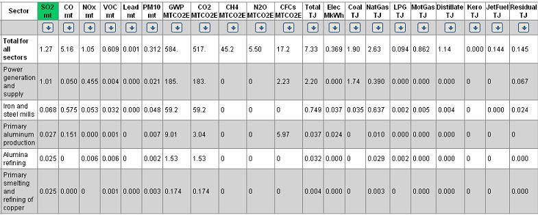
Since the Well's L96 Airsoft gun is a complex piece of machinery to understand its environmental impact a life cycle assessment needs to be performed. A process LCA is beyond the scope of what is feasible for our project so an Economical Input Output Life Cycle Assessment was performed instead. EIO-LCA uses aggregate sector-level data to determine how much environmental impact can be attributed to each sector of the economy. Our market sector is small arms. From the 1997 benchmark input output, not specified by kinds small arm represents less than 10 percent of the small arms commodity output. Airsoft guns are mostly mainly composed of plastics whereas a professional firearm is normally made from metals. Therefore, the EIO-LCA is not a good benchmark for the impact of an airsoft gun.
Possible environmental improvements include but are not limited to:
- lessening the number of parts in the design
- increasing lifespan of product by producing a more durable and maintainable product
- making modular parts so that worn or broken parts can be replaced
- using biodegradable BBs
- improving the distribution of airsofts
Opportunities for Improvements
The following are ideas for improvements that we might implement.
- Turn the Well's L96 Airsoft gun into a hybrid electric gun.
A hybrid electric gun would have more functionality as it would allow for the user to switch between electric and bolt action. There are certain regulations in airsoft games that prevent a sniper gun from being fired at a close distance. An automatic electric gun would allow for the user engage in more close combat action.
- Implement a burst fire mode
A burst fire is a firing mode that allows for a predetermined number of BBs to be fired with a single pull of the trigger.
- Ergonomic improvements
Possible ergonomic improvements include adding a left-handed loading option. The Loading time of the BBs into the magazine should also be decrease. Plans to move the magazine closer is another possiblity.
- Shorten/lengthen the length of barrel
- Improve accuracy and speed of BB leaving the barrel
- Reduce environmental impact
- Reduce cost
Product Usage
Mechanical Analysis
Assumptions:
- No mechanical failure due to stresses in materials
- Small angles of rotation
- Friction is negligible
- Ideal spring loading
- Any other assumptions not listed here will be addressed when the issue arises
The trigger assembly is composed of the trigger, a rotating lever, the piston release, and a mechanical safety. When the safety trigger and the primary trigger are pulled, the lever is pushed and rotates such that the piston release, which would have pressure being applied on it by the compressed spring in the bolt assembly, is released and is free to rotate. The vertical displacement of the right end of the lever must be 2mm downward for this release to occur, meaning the vertical displacement on the left side must be proportional to the lever arms. This ratio is 33mm/26mm = 1.27, meaning the displacement on the left must be 2.54mm.

FT is the force between the trigger and the lever.
Fframe is the force applied by the frame on the trigger. This keeps the trigger in equilibrium when there is not enough force to rotate the trigger. This value is zero when the trigger force passes some critical value. For these calculations, Fframe = 0.
F1 is the force applied by the trigger spring due to its compression. This spring is initially compressed 1mm.
F2 is the force applied by the lever spring due to its compression. This spring is initially compressed 1mm.
F is the force applied at the middle of the curved portion of the trigger.
dT is the moment arm for FT about point O. dT = 33 mm
dt is the moment arm for FT about point P. dt = 7 mm
d1 is the moment arm for F1 about point P. d1 = 10 mm
d2 is the moment arm for F2 about point O. d2 = 20 mm
dframe is the moment arm for Fframe about point O. dT = 13
d is the moment arm for F about point P. d = 25 mm
(insert calculations here)
From measured values, the force required to pull the trigger averaged out to 2.44N over ten trials. Also measured was the safety trigger pull, which averaged out to 0.44N over ten trials. This extra force is required to compress the spring inside the trigger that pushes on the safety trigger. Therefore, the actual force to pull the trigger is about 2.00N.
Links
http://www.airsplat.com/Items/AR-WELL-MB01BSB.htm
http://en.wikipedia.org/wiki/Airsoft
http://www.airsoftgunhelp.com/airsoft-games.htm


