Car Jack Preliminary Analysis
From DDL Wiki
(→Loading Conditions) |
(→Loading Conditions) |
||
| Line 50: | Line 50: | ||
[[Image:Car_jack_upper_arm_buckling_loading_conditions.jpg|300px|left]] | [[Image:Car_jack_upper_arm_buckling_loading_conditions.jpg|300px|left]] | ||
| - | Shown to the left | + | Shown here is the model of the upper arm and with visible loading conditions. The Bearing load of 1lb is used to simulate the force transfer to the upper arm from either the right or left pin. Cylindrical Support 1 simulates the radial and axial constraints applied to this member by the upper pin. Cylindrical Support 2 simulates the tangential constraint applied by the gear profile that mates with the other upper arm. |
Revision as of 22:47, 1 March 2007
Mechanics Of The Car Jack
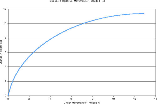
This plot shows the change in height of the top plate with a linear change in distance between the left and right pivot. This demonstrates the non-linearity of the system under usage. From a usage standpoint this non-linearity would require the user to apply a larger torque in the early stages of the lift. As the car is lifted higher the amount of torque needed to cause upward motion will decrease.
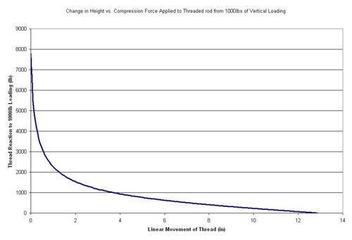
This plot shows the force between the left and right pin that would be applied to the threaded rod under 1000lbs of downward loading. It can be seen that when the jack is in its mostly closed state a much larger force must be applied to the thread to raise the 1000lb load. Under normal conditions the pinch weld of a car is approximately 4 inches off the ground. By this point the system has reached a linear portion of its travel and becomes easier for a person to operate.
Buckling of a upper arm
A simplified model of the upper arm has been modeled in Ansys and analyzed to find its capacity before buckling. The 1st buckling mode was seen at approximately 22,000lbs. A video of this mode shape can be seen here.
Loading Conditions
Shown here is the model of the upper arm and with visible loading conditions. The Bearing load of 1lb is used to simulate the force transfer to the upper arm from either the right or left pin. Cylindrical Support 1 simulates the radial and axial constraints applied to this member by the upper pin. Cylindrical Support 2 simulates the tangential constraint applied by the gear profile that mates with the other upper arm.
--Return to Car jack


