Car jack product dissection
From DDL Wiki
m (Team 8's Product Dissection moved to Car jack product dissection: Please be product-specific with page naming. Also, use all lower case except for proper nouns and acronyms - this will help with linking.) |
(→Bill of Materials) |
||
| Line 14: | Line 14: | ||
|0004||Top||1||6.2||Connects upper arms, links 4-bar linkage, connection point and support for vehicle||Steel, powder coated||Stamped and bent||[[Image:Team8 Top botv.JPG|50px]][[Image:Team8 Top topv.JPG|50px]][[Image:Team8 Top Sidev.JPG|50px]] | |0004||Top||1||6.2||Connects upper arms, links 4-bar linkage, connection point and support for vehicle||Steel, powder coated||Stamped and bent||[[Image:Team8 Top botv.JPG|50px]][[Image:Team8 Top topv.JPG|50px]][[Image:Team8 Top Sidev.JPG|50px]] | ||
|- | |- | ||
| - | |0005||Left Pin||1||6.0||Tapped with matching thread to hold and allow threaded rot to rotate, also connects lower and upper left arms||Steel||||[[Image:Team8 left pin.JPG|50px]][[Image:Team8 pin side.JPG|50px]] | + | |0005||Left Pin||1||6.0||Tapped with matching thread to hold and allow threaded rot to rotate, also connects lower and upper left arms||Steel||Extruded, drilled and threaded||[[Image:Team8 left pin.JPG|50px]][[Image:Team8 pin side.JPG|50px]] |
|- | |- | ||
| - | |0006||Right Pin||1||5.7||Acts as a top for thrust bearing, connects right lower and upper arms, holds in position and serves as a guide for threaded rod||Steel||||[[Image:Team8 right pin.JPG|50px]][[Image:Team8 pin side.JPG|50px]] | + | |0006||Right Pin||1||5.7||Acts as a top for thrust bearing, connects right lower and upper arms, holds in position and serves as a guide for threaded rod||Steel||Extruded, and drilled||[[Image:Team8 right pin.JPG|50px]][[Image:Team8 pin side.JPG|50px]] |
|- | |- | ||
| - | |0007||Threaded Rod||1||15.6||Acme threaded rod, with eyelet at the end, when rotated pulls sides together providing upward motion and force||Steel||||[[Image:Team8 thread.JPG|50px]][[Image:Team8 threaded rod.JPG|50px]] | + | |0007||Threaded Rod||1||15.6||Acme threaded rod, with eyelet at the end, when rotated pulls sides together providing upward motion and force||Steel||Extruded, threaded||[[Image:Team8 thread.JPG|50px]][[Image:Team8 threaded rod.JPG|50px]] |
|- | |- | ||
|0008||Collar||1||1||Serves as a stop for the threaded rod, keeps it from overturning||Steel||||[[Image:Team8 collar.JPG|50px]] | |0008||Collar||1||1||Serves as a stop for the threaded rod, keeps it from overturning||Steel||||[[Image:Team8 collar.JPG|50px]] | ||
|- | |- | ||
| - | |0009||Thrust Bearing||1||1||Allows rod to rotate under force, keeps jack working when threaded rod is under force from the car||Steel||||[[Image:Team8 bearing.JPG|50px]] | + | |0009||Thrust Bearing||1||1||Allows rod to rotate under force, keeps jack working when threaded rod is under force from the car||Steel||Purchased||[[Image:Team8 bearing.JPG|50px]] |
|- | |- | ||
| - | |0010||Lower Pin||2||1.2||Acts as a pivot point, secures lower arms to base, longer than upper pins||Steel||||[[Image:Team8 pins.JPG|50px]] | + | |0010||Lower Pin||2||1.2||Acts as a pivot point, secures lower arms to base, longer than upper pins||Steel||Extruded, mushroomed at ends||[[Image:Team8 pins.JPG|50px]] |
|- | |- | ||
| - | |0011||Upper Pin||2||1||Acts as a pivot point, secures upper arms to top, shorter than lower pins||Steel||||[[Image:Team8 pins.JPG|50px]] | + | |0011||Upper Pin||2||1||Acts as a pivot point, secures upper arms to top, shorter than lower pins||Steel||Extruded, mushroomed at ends||[[Image:Team8 pins.JPG|50px]] |
|- | |- | ||
| - | |0012||Crank Arm||1||11.7||Lever arms used to rotate threaded rod||Steel||||[[Image:Team8 crank arm.JPG|50px]] | + | |0012||Crank Arm||1||11.7||Lever arms used to rotate threaded rod||Steel||Extruded, bent||[[Image:Team8 crank arm.JPG|50px]] |
|} | |} | ||
Revision as of 14:41, 9 February 2007
Dissection Process
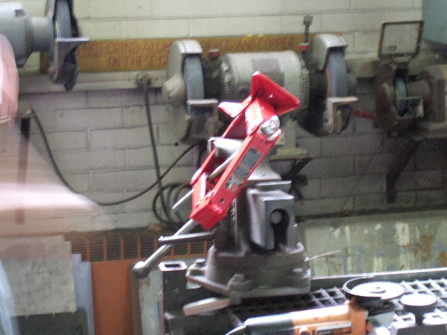
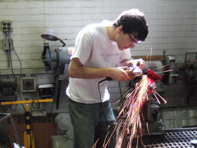
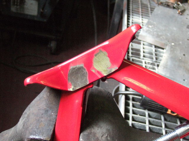
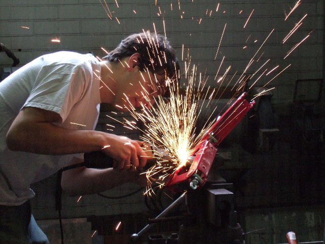
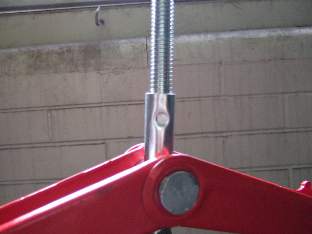
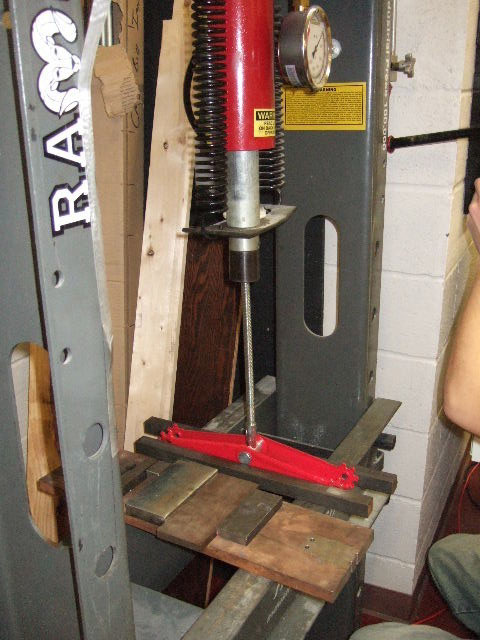
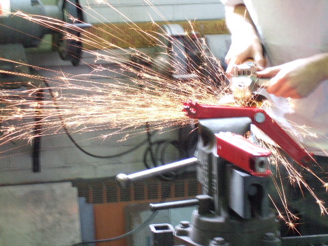
Given the construction process of the jack, dissection could not be done in the lab and had to be done in the machine shop (The jack in a vice awaiting dissection). The pins connecting the arms to the top and base were riveted on. To remove them, we used an angle grinder, and ground off one end of the pin allowing the pin to be pushed out. This was first done to the base pins (Matt grinding off rivets on the base pins, Base after rivets ground off ). After this the pins were pushed through allowing the base to be removed. When this was completed, the process was repeated for the pins attaching the arms to the top (Matt grinding rivets off the top pins,Top after rivets ground off). After pushing he top pins out the top could then be removed. After this step the the right arms and the left arm/threaded-arms assembly could be separated. Next the collar securing the threaded rod was removed (Threaded rod with collar). As the collar was pinched onto the rod, removal was difficult. To accomplish this the collar and rod were placed in vice to bend the collar out slightly, a press and later a hammer were used to finish the removal (Collar and rod assembly in a press). With the collar removed the threaded rod could them be removed from the left pin. This last step in the dissection was to remove the right pins and separate the right arms and do the same to the left. The right and left pins had notches that were bend back onto the arms to secure them. To remove the pin the notches were ground off with the angle grinder (Matt removing the notches with an angle grinder). With the notches removed the pins could then be pushed out and the arms separated. After this was completed , we photographed and documented each piece to complete the dissection.
Bill of Materials
| Part # | Part Name | Qty. | Weight(oz.) | Function | Material | Manufacturing Process | Images |
|---|---|---|---|---|---|---|---|
| 0001 | Base | 1 | 14.7 | Connection point for lower arms, supports jack against ground | Steel, powder coated | Stamped and bent | |
| 0002 | Lower Arm | 2 | 12.2 | Lower part of 4-bar linkage that makes up jack | Steel, powder coated | Stamped and bent | |
| 0003 | Upper Arm | 2 | 12.2 | Upper part of 4-bar linkage that make up jack | Steel, powder coated | Stamped and bent | |
| 0004 | Top | 1 | 6.2 | Connects upper arms, links 4-bar linkage, connection point and support for vehicle | Steel, powder coated | Stamped and bent | |
| 0005 | Left Pin | 1 | 6.0 | Tapped with matching thread to hold and allow threaded rot to rotate, also connects lower and upper left arms | Steel | Extruded, drilled and threaded | |
| 0006 | Right Pin | 1 | 5.7 | Acts as a top for thrust bearing, connects right lower and upper arms, holds in position and serves as a guide for threaded rod | Steel | Extruded, and drilled | |
| 0007 | Threaded Rod | 1 | 15.6 | Acme threaded rod, with eyelet at the end, when rotated pulls sides together providing upward motion and force | Steel | Extruded, threaded | |
| 0008 | Collar | 1 | 1 | Serves as a stop for the threaded rod, keeps it from overturning | Steel | ||
| 0009 | Thrust Bearing | 1 | 1 | Allows rod to rotate under force, keeps jack working when threaded rod is under force from the car | Steel | Purchased | |
| 0010 | Lower Pin | 2 | 1.2 | Acts as a pivot point, secures lower arms to base, longer than upper pins | Steel | Extruded, mushroomed at ends | |
| 0011 | Upper Pin | 2 | 1 | Acts as a pivot point, secures upper arms to top, shorter than lower pins | Steel | Extruded, mushroomed at ends | |
| 0012 | Crank Arm | 1 | 11.7 | Lever arms used to rotate threaded rod | Steel | Extruded, bent |
Go back to Car jack
--Alberto Guzman - 28 Jan 2007
