Ceiling-mounted bicycle lift structural analysis
From DDL Wiki
(Difference between revisions)
m |
m |
||
| Line 11: | Line 11: | ||
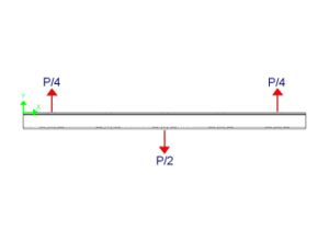
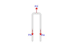
P/2 = 111.2 N<br /> | P/2 = 111.2 N<br /> | ||
P/4 = 55.6 N<br /> | P/4 = 55.6 N<br /> | ||
| + | <br /> | ||
| + | (P = 50 lbs)<br /> | ||
|- align="left" | |- align="left" | ||
| [[Image:Team1-FBD-Bracket.JPG|300px]] || '''Bending along X-axis'''<br /> | | [[Image:Team1-FBD-Bracket.JPG|300px]] || '''Bending along X-axis'''<br /> | ||
| Line 22: | Line 24: | ||
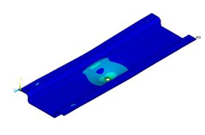
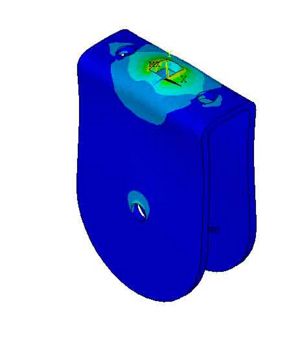
| [[Image:Team1-Stress-Bracket.JPG|300px]] || '''Bending along Z-axis'''<br /> | | [[Image:Team1-Stress-Bracket.JPG|300px]] || '''Bending along Z-axis'''<br /> | ||
Distance between support forces: 70 mm<br /> | Distance between support forces: 70 mm<br /> | ||
| - | Vertical centroid: -. | + | Vertical centroid: -.66 mm (measure from top surface)<br /> |
Second moment of area about centroidal axis: 37.8 mm<sup>4</sup><br /> | Second moment of area about centroidal axis: 37.8 mm<sup>4</sup><br /> | ||
Maximum bending moment: 1,946 N*mm<sup>2</sup><br /> | Maximum bending moment: 1,946 N*mm<sup>2</sup><br /> | ||
| Line 53: | Line 55: | ||
P/2 = 111.2 N<br /> | P/2 = 111.2 N<br /> | ||
P/4 = 55.6 N<br /> | P/4 = 55.6 N<br /> | ||
| + | <br /> | ||
| + | (P = 50 lbs)<br /> | ||
|- align="left" | |- align="left" | ||
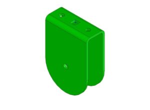
| [[Image:Team1-FBD-UPulley.JPG|300px]] || '''Bending along X-axis'''<br /> | | [[Image:Team1-FBD-UPulley.JPG|300px]] || '''Bending along X-axis'''<br /> | ||
| - | Distance between support forces: | + | Distance between support forces: 20 mm<br /> |
| - | Vertical centroid: - | + | Vertical centroid: -.66 mm (measure from top surface)<br /> |
| - | Second moment of area about centroidal axis: | + | Second moment of area about centroidal axis: 3.03 mm<sup>4</sup><br /> |
| - | Maximum bending moment: | + | Maximum bending moment: 556 N*mm<sup>2</sup><br /> |
<br /> | <br /> | ||
| - | Maximum x-bending stress: | + | Maximum x-bending stress: 12.1 N/mm<sup>2</sup> = 12.1 Mpa<br /> |
|- align="left" | |- align="left" | ||
| - | | [[Image:Team1-Stress-UPulley.JPG|300px]] || | + | | [[Image:Team1-Stress-UPulley.JPG|300px]] || '''Stress Concentration Factor'''<br /> |
| - | + | ||
| - | + | ||
| - | + | ||
| - | + | ||
| - | + | ||
| - | + | ||
| - | + | ||
| - | + | ||
| - | + | ||
| - | '''Stress Concentration Factor'''<br /> | + | |
h = 1.22 mm (sheet thickness)<br /> | h = 1.22 mm (sheet thickness)<br /> | ||
| - | w = | + | w = 48 mm (section width)<br /> |
d = 6 mm (hole size)<br /> | d = 6 mm (hole size)<br /> | ||
<br /> | <br /> | ||
| - | d/w = . | + | d/w = .13 d/h = 5<br /> |
K = 1.7 - From table A-15-12 of (Shigley, Mechanical Engineering Design)<br /> | K = 1.7 - From table A-15-12 of (Shigley, Mechanical Engineering Design)<br /> | ||
<br /> | <br /> | ||
| - | '''<big>Actual Maximum Stress = | + | '''<big>Actual Maximum Stress = 20.6 Mpa<br /></big>''' |
| + | |} | ||
Revision as of 00:47, 8 March 2007
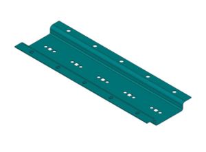
Part # 001: Ceiling Bracket
Stress Concentration Factor
h = 1.22 mm (sheet thickness)
w = 50 mm (section width)
d = 6 mm (hole size)
d/w = .12 d/h = 5
K = 1.7 - From table A-15-12 of (Shigley, Mechanical Engineering Design)
Actual Maximum Stress = 17.1 Mpa
