Chain drive opportunity
From DDL Wiki
Contents |
Executive Summary
Market Research
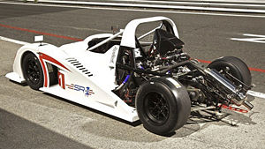
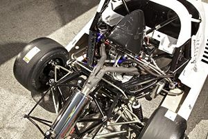
In order to ascertain the market in which this product would exist we looked into the needs of small scale racing teams, such as Formula SAE teams and more widespread amateur racing series. This includes entry level series such as the Radical SR1 cup and other racing cars built to use motorcycle engines. In order to make informed decisions we performed a user study and interview, Interviews with professionals and survey results.
Stakeholder Needs
Because we are exploring a new product and market space we must re-define our stakeholders. The primary stakeholders in this supply chain are the manufacturers, racing shops/online retailers and the racing customer.
Consumers:
Consumers are the target audience who purchases the product, these people race dedicated track cars on the weekends. They may have built these vehicles themselves or purchased the chassis from a company like Radical.
- Ease of use for both alignment and tensioning of the rear differential
- Robust construction for reliable track use
- Low weight because this is racing vehicle
- Lowest possible cost for a quality product as these vehicles are supposed to be low cost racers
- Ease of maintenance
- Compatible with many frame and differential design, IE not a custom part for each vehicle
- Easily installed vehicles not currently using it
- Weather resistance
Retailers:
These are the people and companies that would sell the product to the consumers
Most likely this would be from specialized race shops or from online retailers like Summit Racing.
- Small size for easy storage
- Possibility of flat packing
- Universal compatibility use so they do not have to stock more than a couple sized/configurations
- Ease of maintenance for customers who do not wish to do this themselves
- Low price
- As little hardware as possible
Manufacturers:
Manufacturers create the product for sale and effects on time and pricing impact the entire supply chain.
- Time to manufacture is important and all custom machined parts slow down the process
- Cost to manufacture and of materials; exotic materials would not be good here.
Competitor Products
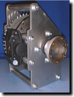
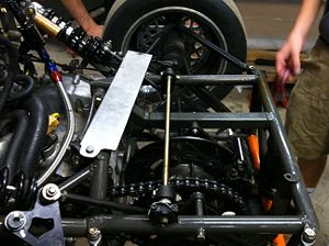
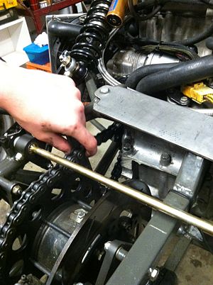
Before deciding on a path for the rest of the market research we first looked for competitor products in the market space we defined. This meant looking both at Formula SAE and for other motorcycle engine powered low cost race cars. In the FSAE market there are several differential designs provided by companies such as Taylor Racing and Drexler. These Differentials leave the mounting up to the customer, a prospect that with Formula SAE is relatively common. However, these differentials get used in hobby cars as well as vehicles such as Radical's new SR1 which use chain drive. Mostly support and pretension for the differential is an afterthought for the company selling the differential. This is where market space exists. As we found and are documented in the pictures below these mounting plates look similar in function to what we have currently on our FSAE race car. The pivoting turnbuckle style is typical in this situation. These products also do not provide the consumer with many of their needs as a stakeholder. A lot is left to be desired in terms of universal mounting and also weight.
User Study
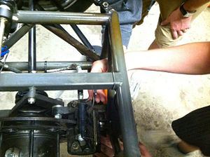
We designed a study to identify normal issues with the pretension and function of maintenance on the drivetrain of the Carnegeie Mellon Racing Formula SAE car. This vehicle is representative of the set up used both in the FSAE series but also in other low cost racing series where chain drive is prefered. Two mechanically inclined individuals who did not have prior knowledge of the car’s design were asked to loosen the chain completely and re-tighten the driveline. This procedure allows us to artificially create a situation of a loose chain.
The first thing observed in this study was that access to adjustment turnbuckles was very limited. This was compounded by the fact that tools were not common between the separate locking nuts and the turnbuckles. The lack of access and direct line of sight also made finding the position desired for the plates was hard. The users attempted to gauge position of the plate via number of turns on the turn buckles. This concept could be used in the future to help locate differential plate position. However, on the current set up the number of turns did not create the same movement between the two sides, making this method useless.
While the users were working it was clear that this was also a dirty project. While not a direct stakeholder need, the ability to quickly and cleanly perform maintenance is a plus for all consumers.
Towards the end of the work we noticed a lot of confusion in determining how tight the chain needed to be and whether the differential housing was indeed aligned properly. This meant a lot of time wasted trying to figure out how to determine these specifications and also how to indicate if they were within spec. “When are we done here?” was the common phrase used. This shows a key flaw in the system, there is no way to indicate alignment and tension on the plates. They ended up just pulling on the chain to determine tension (a feeler method) and then standing back a bit and closing one eye to gauge alignment. It seemed as though they got a grasp on the whole process fairly well but had no idea if they met the end criteria. There is no specification for chain tension on a project like this (custom race car) and while trying to also align the differential this made determining when they were finished hard. With an easy method to measure position or a discrete number of locations this problem would be eliminated.
User Interviews
Expert Interview
Design Concepts
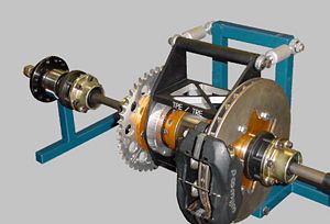
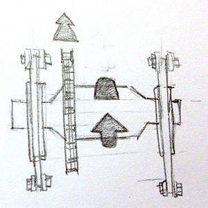
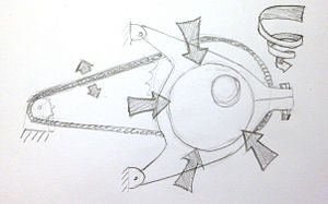
All differential mounting options share some common features, as can be generalized in the view below.
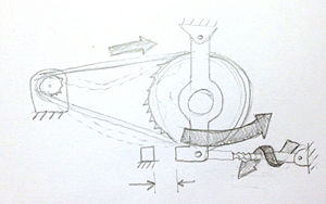
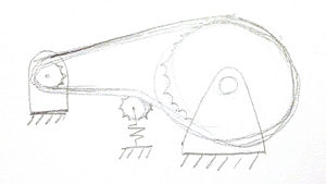
The setup contains a pair of mounting plates that allow the differential to rotate freely, dividing available torque to the wheels. In addition to locating the differential, the mounting plates must adequately react the tensile spike loads carried through the chain off the motor's drive sprocket. The tension and alignment of the chain is critical to a reliable, high efficiency vehicle. Because of this fact, three designs were developed that deal with properly aligning and tensioning the chain and are detailed below.
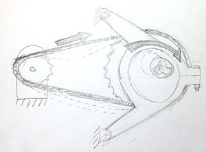
The first mechanism has a pair of symmetrical plates with an outer A frame and inner eccentric plate. The first component is the horizontal A frame which has features on the top and bottom suitable for mounting to a forward chassis tube. The A frame is also bored out for the inner eccentric mount. The final feature is a split at the tip of the 'A' that allows a bolt to pass through and apply a clamping pressure on the inner eccentric mount. Before that bolt is tightened and the clamping force applied, the inner eccentric mount is free to rotate, providing fore-aft translation of the differential and sprocket, allowing slack to be removed from the chain.
Pugh Chart
Gantt Chart
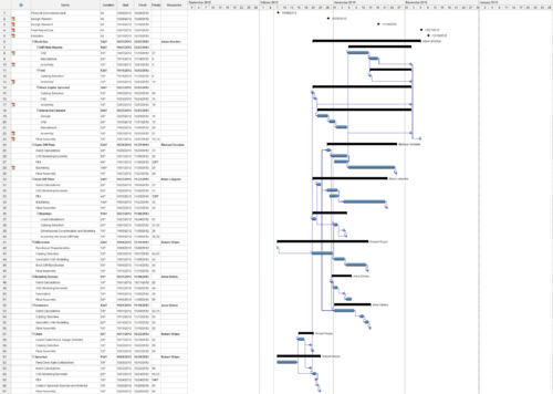
The Phase III timeline is broken down into component level design, analysis, manufacture, and integration. Each team member is assigned a specific set of components to optimize and specify. The deadlines for design review I, II and the final reviews are indicated at the top of the chart. Although not explicitly indicated, prototypes for design reviews I and II will be made to demonstrate mechanisms and as proofs of concept.
