Drawing
From DDL Wiki
| Line 26: | Line 26: | ||
==Advantages and Disadvantages== | ==Advantages and Disadvantages== | ||
| - | + | One clear advantage of drawing is the simplicity of the components required to complete the process. Another advantage of the process is the cost-effectiveness and speed of using a continuous process with permanent components. Furthermore, drawing can be applied both as a hot or cold process, and is applicable to various materials and products. | |
| - | + | ||
| - | + | There are a few disadvantages to the drawing process that must be considered during a design stage. One of these is the limitation on cross-sectional area reduction mentioned above. Due to the amount of cold work that is imparted on the material during each pass, the reduction in cross-sectional area must be controlled stringently so that a process may require several die passes. Another disadvantage is the rate at which dies may wear out due to work hardening of the material. However, this fault may be mitigated by the use of correct lubrication and by controlling the speed of material passing through the die. | |
=External Links= | =External Links= | ||
Revision as of 14:17, 8 September 2007
Contents |
Description
Drawing is a manufacturing process commonly used to control the cross-sectional area of a wire, rod, or bar. In this process the wire or rod is drawn through a converging die which has a smaller diameter than the incoming material. Although the most common application of drawing is wire drawing, the die may have any cross section so that the process is applicable to several different products. Drawing is typically used as a finishing process. Thus, the final product from drawing will likely not pass through any further manufacturing steps.
A notable distinction to make when considering drawing, is that the material passing through the die is in tension during the process. This is in contrast to the process of extrusion, where the material passing through the die is in compression.
Process
In a manufacturing setting, there are several components to a wire drawing process. The image above illustrates a typical process:
- 1. Load wire/material onto a draw block
- 2. Wire passes through control sheave
- 3. Wire is drawn through the die
- 4. The finish draw block spins to collect wire coming through the die
- 5. Repeat through multiple dies as necessary
The finish draw block spins to pull wire through the die. The control sheave (or speed control wheel) may also spin in order to control the speed of the wire through the die. This may also be used to lower the tension in the wire while passing through the die so that the stress in the material is decreased.
Components and Configuration
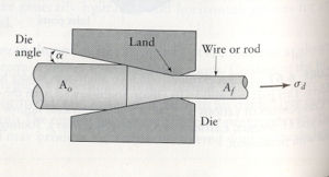
The image to the right shows the components important in drawing. A wire or rod of an original cross section (Ao) passes through a converging die. The angle at which the area of the die decreases is called the die angle (alpha). The land is the point in the die which has the smallest cross sectional area. This part of the die sets the final angle of the wire, rod, or bar. The die then diverges slightly after the land to allow for expansions of the material past this point. This may occur due to strain in the material's cross-sectional area within the elastic regime. The material with a final cross-sectional area (Af) passes out of the die. A tensile force is applied uniformly across the cross-sectional area of the wire throughout the process by the final draw block pulling the wire through the die.
Design Considerations
Drawing can be used to manufacture wires, flat sheets, tubes, rods, and other products that have a continuous cross-section. Materials typically used in this process include copper, aluminum, steel, brass, bronz, tungsten, and silver. More malleable materials are better suited for this process since they create less wear on the dies. As well as material considerations, lubricants are also used in order to protect the dies. Either dry or wet lubricants may be used depending on what is desired from the process.
One consideration that must be made to design a drawing process is the percent reduction in cross-sectional area allowed per pass. The equations to the right assume uniform stress across the cross-sectional area of the material passing through the die. From these equations, the greatest percent reduction in cross-sectional area that can be made per pass is 63 percent. If any greater reduction is made, the material will yield. (Note that in these equations, Y is the yield strength of the material, and other variables are labeled in images above.)
Advantages and Disadvantages
One clear advantage of drawing is the simplicity of the components required to complete the process. Another advantage of the process is the cost-effectiveness and speed of using a continuous process with permanent components. Furthermore, drawing can be applied both as a hot or cold process, and is applicable to various materials and products.
There are a few disadvantages to the drawing process that must be considered during a design stage. One of these is the limitation on cross-sectional area reduction mentioned above. Due to the amount of cold work that is imparted on the material during each pass, the reduction in cross-sectional area must be controlled stringently so that a process may require several die passes. Another disadvantage is the rate at which dies may wear out due to work hardening of the material. However, this fault may be mitigated by the use of correct lubrication and by controlling the speed of material passing through the die.


