Folding Desk Chair Innovation
From DDL Wiki
(→Design Analysis) |
(→Design Documentation) |
||
| Line 2: | Line 2: | ||
==Market Analysis== | ==Market Analysis== | ||
==Design Documentation== | ==Design Documentation== | ||
| + | ===Bill of Materials === | ||
| + | |||
| + | {|border="1" cellpadding="5" | ||
| + | |- | ||
| + | ! Part # | ||
| + | ! Part Name | ||
| + | ! QTY | ||
| + | ! Weight (g) | ||
| + | ! Function | ||
| + | ! Manufacturing | ||
| + | ! Material | ||
| + | ! Image | ||
| + | |- | ||
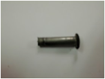
| + | | 1 | ||
| + | | Large Rivet Nut | ||
| + | | 4 | ||
| + | | 6 | ||
| + | | Connects seat (19) to legs (20, 22) | ||
| + | | Purchased | ||
| + | | steel | ||
| + | | [[Image:Row1.png]] | ||
| + | |- | ||
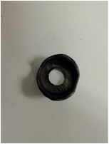
| + | | 2 | ||
| + | | Spacer | ||
| + | | 4 | ||
| + | | 1.5 | ||
| + | | Distances legs from seat, most likely to reduce friction during use | ||
| + | | Purchased | ||
| + | | steel | ||
| + | | [[Image:Row2.png]] | ||
| + | |- | ||
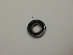
| + | | 3 | ||
| + | | Washer | ||
| + | | 4 | ||
| + | | 1.5 | ||
| + | | Protects coating | ||
| + | | Purchased | ||
| + | | steel | ||
| + | | [[Image:Row3.png]] | ||
| + | |- | ||
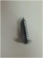
| + | | 4 | ||
| + | | Tapping Screw | ||
| + | | 6 | ||
| + | | 2.5 | ||
| + | | Connects seatback (12) to front legs (22) | ||
| + | | Purchased | ||
| + | | stainless steel | ||
| + | | [[Image:Row4.png]] | ||
| + | |- | ||
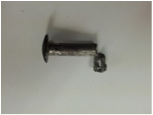
| + | | 5 | ||
| + | | Small Rivet Nut | ||
| + | | 4 | ||
| + | | 4 | ||
| + | | Connects bracket (6) to legs (20, 22) | ||
| + | | Purchased | ||
| + | | steel | ||
| + | | [[Image:Row5.png]] | ||
| + | |- | ||
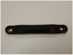
| + | | 6 | ||
| + | | Bracket | ||
| + | | 2 | ||
| + | | 27 | ||
| + | | Holds legs (20, 22) together and acts as hinge | ||
| + | | Stamped | ||
| + | | steel | ||
| + | | [[Image:Row6.png]] | ||
| + | |- | ||
| + | | 7 | ||
| + | | Rubber foot covering | ||
| + | | 4 | ||
| + | | 4 | ||
| + | | Protects flooring | ||
| + | | Injected molding and joined | ||
| + | | Rubber | ||
| + | | [[Image:Row7.png]] | ||
| + | |- | ||
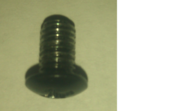
| + | | 8 | ||
| + | | Small machine screw | ||
| + | | 6 | ||
| + | | 1.5 | ||
| + | | Connects cushion assembly to seat (19) | ||
| + | | Purchased | ||
| + | | Steel | ||
| + | | [[Image:Blackscrew.png|thumb]] | ||
| + | |- | ||
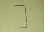
| + | | 9 | ||
| + | | Staples | ||
| + | | | ||
| + | | | ||
| + | | Connects fabric (13) to seat back (12) and cardboard seat (18) | ||
| + | | Purchased | ||
| + | | Steel | ||
| + | | [[Image:Staple1.png|thumb]] | ||
| + | |- | ||
| + | | 10 | ||
| + | | Large staple cover bracket | ||
| + | | 1 | ||
| + | | 10 | ||
| + | | Covers the area where staples are visible for aesthetic and safety purposes | ||
| + | | Molded | ||
| + | | Plastic | ||
| + | | [[Image:Row10.png]] | ||
| + | |- | ||
| + | | 11 | ||
| + | | Small staple cover bracket | ||
| + | | 1 | ||
| + | | <1 | ||
| + | | Covers the area where staples are visible for aesthetic and safety purposes | ||
| + | | Molded | ||
| + | | Plastic | ||
| + | | [[Image:Row11.png]] | ||
| + | |- | ||
| + | | 12 | ||
| + | | Seatback | ||
| + | | 1 | ||
| + | | 279 | ||
| + | | Provides back support | ||
| + | | Molded | ||
| + | | Plastic | ||
| + | | [[Image:Row12.png]] | ||
| + | |- | ||
| + | | 13 | ||
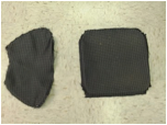
| + | | Fabric Covers | ||
| + | | 2 | ||
| + | | 55 | ||
| + | | Covers cusion, keeping foam (16, 17) in place and making the seat aesthetic | ||
| + | | Woven, dyed, and cut | ||
| + | | Nylon | ||
| + | | [[Image:Row13.png]] | ||
| + | |- | ||
| + | | 14 | ||
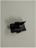
| + | | Angle Stop | ||
| + | | 2 | ||
| + | | 5 | ||
| + | | Stop front legs at a certain angle and protects material | ||
| + | | Molded and joined | ||
| + | | Rubber | ||
| + | | [[Image:Row14.png]] | ||
| + | |- | ||
| + | | 15 | ||
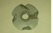
| + | | Tee Nut | ||
| + | | 6 | ||
| + | | 1 | ||
| + | | Allows screws to hold cushion to seat | ||
| + | | Purchased | ||
| + | | Steel | ||
| + | | [[Image:flyscrew.png|thumb]] | ||
| + | |- | ||
| + | | 16 | ||
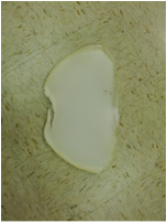
| + | | Seatback Foam | ||
| + | | 1 | ||
| + | | 24 | ||
| + | | Cushions seat back for comfort | ||
| + | | Cut | ||
| + | | Polyurethane | ||
| + | | [[Image:Row16.png]] | ||
| + | |- | ||
| + | | 17 | ||
| + | | Seatback Foam | ||
| + | | 1 | ||
| + | | 56 | ||
| + | | Cushions seat for comfort | ||
| + | | Cut | ||
| + | | Polyurethane | ||
| + | | [[Image:Row17.png]] | ||
| + | |- | ||
| + | | 18 | ||
| + | | Fiberboard Seat Cover | ||
| + | | 1 | ||
| + | | 332 | ||
| + | | Holds screws and staples for seat assembly | ||
| + | | Cut | ||
| + | | Fiberboard | ||
| + | | [[Image:Row18.png]] | ||
| + | |- | ||
| + | | 19 | ||
| + | | Seat | ||
| + | | 1 | ||
| + | | 1366 | ||
| + | | Holds cushion and provides support | ||
| + | | Forged | ||
| + | | Steel | ||
| + | | [[Image:Row19.png]] | ||
| + | |- | ||
| + | | 20 | ||
| + | | Back leg | ||
| + | | 2 | ||
| + | | rowspan="2"|394 | ||
| + | | Distributes weight from seat | ||
| + | | Drawn and cut | ||
| + | | Steel | ||
| + | | rowspan="2"|[[Image:Row20.png]] | ||
| + | |- | ||
| + | | 21 | ||
| + | | Crossbeam | ||
| + | | 1 | ||
| + | | Strengthens back leg | ||
| + | | Drawn and cut | ||
| + | | Steel | ||
| + | |- | ||
| + | | 21 | ||
| + | | Crossbeam | ||
| + | | 1 | ||
| + | | rowspan="2"|1360 | ||
| + | | Strengthens front leg | ||
| + | | Drawn and cut | ||
| + | | Steel | ||
| + | | rowspan="2"|[[Image:Row21.png]] | ||
| + | |- | ||
| + | | 22 | ||
| + | | Front leg | ||
| + | | 1 | ||
| + | | Distributes weight from seat | ||
| + | | Drawn, cut, and bent | ||
| + | | Steel | ||
| + | |} | ||
| + | |||
==House of Quality== | ==House of Quality== | ||
==Design Analysis== | ==Design Analysis== | ||
Revision as of 00:24, 2 May 2012
Contents |
Executive Summary
Market Analysis
Design Documentation
Bill of Materials
House of Quality
Design Analysis
DFMA
Design for Manufacture and Assembly considerations were significant to the prototype and design analysis. As the DFMA implications are expanded to the large scale production regime, several conclusions become apparent. If implemented on a large scale, the folding desk chair would be composed of two major subassemblies: a stock folding chair (likely very similar to the black Target model used in our physical prototype), and the custom desk and arm assembly. This means that other than the simple variations made to the folding chair (holes to mount hardward) after assembly in its own factory, all DFMA considerations for this project lie in the desk, arm and hinge subassembly. Firstly, stock tubing is used to form the main pivot arm. In this and all cases, use of fastners is minimized by using as few parts as possible. In this example, bending stock tubing is the simplest way to make the custom pivot arm. Attaching the main arm to to the chair and hinge on each end is also done using DFMA considerations, by using rivets and spring pins rather than traditional fastners. This is because fastners such as rivets and pins are easier to install, cheaper, and their inherent drawback of permanency doesn't matter in our design. Once the chair is assembled, it need not be disassembled.
FMEA
Failure Mode Effects Analysis was the largest and most important aspect of the Design Aspect facet.
