|
|
| Line 1: |
Line 1: |
| | + | [[Image:IC assembly.JPG]] |
| | + | |
| | ==Executive Summary== | | ==Executive Summary== |
| | | | |
| Line 119: |
Line 121: |
| | |- | | |- |
| | ! 012 | | ! 012 |
| - | | Mixing Gear Seal || 1 || Provides a seal between the mixing gear and the top of the base so that ingredients do not drop into the motor area || Rubber composite || Injection molding|| [[Image:IC mixing gear rubber.JPG]] | + | | Mixing Gear Seal || 1 || Provides a seal between the mixing gear and the top of the base so that i |
| - | |-
| + | |
| - | ! 013
| + | |
| - | | Mixing Gear || 1 || Turned by the drive gear and in turn rotates the mixing bowl || Plastic || Injection Molding|| [[Image:IC mixing gear.JPG]]
| + | |
| - | |-
| + | |
| - | ! 014
| + | |
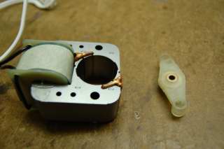
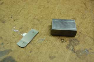
| - | | Motor Base || 50 - Shims<br /><br />2 - Copper Wires || Provides housing for all motor components and creates an alternating magnetic field generated by the Motor Coil Assembly to run the motor spindle || Steel, Copper || Shims - Stamped<br /><br />Copper - Extrusion/Rolled|| [[Image:IC motor base.JPG]]
| + | |
| - | |-
| + | |
| - | ! 015
| + | |
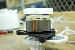
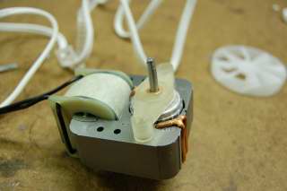
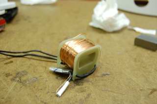
| - | | Motor Coil Assembly || 1 - copper coil<br /><br /> 1 - Coils Spindle<br /><br />50 - Shims <br /><br /> 2 - Wires || Assembly made of copper coil wrapped around a plastic base. Receives a current from the electricity source which is then used to generate a magnetic field || Steel, Plastic, Copper || Coil - Extrusion<br /><br />Shims - Stamping<br /><br />Spindle - Injection molding|| [[Image:IC motor coil assembly.JPG]]
| + | |
| - | |-
| + | |
| - | ! 016
| + | |
| - | | Motor || 1 || Motor component which is rotated as a result of the magnetic field. Turns the drive gear which in turn rotates the mixing gear. || Steel || Electrical Assembly <br /><br /> Case - Drawn|| [[Image:IC motor rotator.JPG]]
| + | |
| - | |-
| + | |
| - | ! 017
| + | |
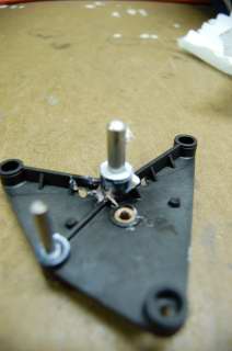
| - | | Motor Spindle Holder || 1 || Holds the motor spindle in place at the top of the base where the drive gear is attached. Provides an starting anchor point of the long screws. || Plastic || Injection Molding|| [[Image:IC motor spindle holder.JPG]]
| + | |
| - | |-
| + | |
| - | ! 018
| + | |
| - | | Motor Wrapping || 1 || Paper used to hold the motor copper coil in place and stop it from unraveling || Paper || Mechanical Pulping|| [[Image:IC motor wrapping.JPG]]
| + | |
| - | |-
| + | |
| - | ! 019
| + | |
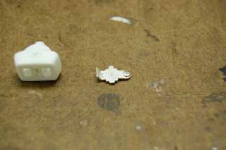
| - | | On/Off Switch Assembly || 1 - Switch base<br /><br />1 - Switch Mechanism<br /><br />1 - Metal Contact || A mechanism used to open and close a circuit to allow users to manually stop and start the ice cream maker. || Plastic, Aluminum || Plastic - Injection molding<br /><br />Aluminum - Stamping|| [[Image:IC on off mechanism.JPG]][[Image:IC on off switch assembly.JPG]]
| + | |
| - | |-
| + | |
| - | ! 020
| + | |
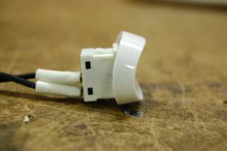
| - | | On/Off Switch || 1 || A user friendly switch that allows users to operate the On/Off switch assembly || Plastic || Injection Molding|| [[Image:IC on off switch.JPG]]
| + | |
| - | |-
| + | |
| - | ! 021
| + | |
| - | | Rubber Stopper || 1 || Provides a mechanism to stop the ice cream maker from sliding across what ever surface it is on while prevent users from reaching the screws which hold the base together. || Rubber composite || Injection molding|| [[Image:IC rubber stopper.JPG]]
| + | |
| - | |-
| + | |
| - | ! 022
| + | |
| - | | Wire Caps || 2 || Provides a safe way to keep wire ends held together || Plastic || Injection molding|| [[Image:IC wire caps.JPG]]
| + | |
| - | |-
| + | |
| - | ! 023
| + | |
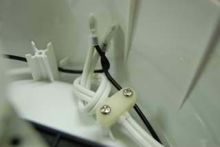
| - | | Wire Hold Down || 1 || Keeps the wire in the base away from moving parts || Plastic || 1-Part Mold|| [[Image:IC wire holder.JPG]]
| + | |
| - | | + | |
| - | | + | |
| - | |}
| + | |
| - | | + | |
| - | =Design for Manufacture and Assembly (DFMA)=
| + | |
| - | | + | |
| - | A “Design for Manufacture and Assembly” (DFMA) analysis of the product gives valuable insight into areas in the design process that can be improved to lower the cost of the product essentially by making the both the manufacturing and assembly processes easier. The following discussion examines why certain parts of the ice cream maker were made using the specified manufacturing process. It also discusses possible ways to improve the design by either reducing the number of parts (to reduce cost of manufacturing) or redesigning parts to make the assembly process easier (to reduce the time associated with assembly of the product). A DFMA analysis complements a Failure Modes Effects Analysis (FMEA) in that it seeks to improve the product in ways not just limited to parts of the product that may break.
| + | |
| - | | + | |
| - | ==Design for Manufacture (DFM)==
| + | |
| - | A design for manufacture analysis discusses how each individual part of the ice cream maker was manufactured and seeks to optimize the ease and cost of manufacturing. Below, the analysis is broken down into the main parts of the ice cream maker that were manufactured.
| + | |
| - | | + | |
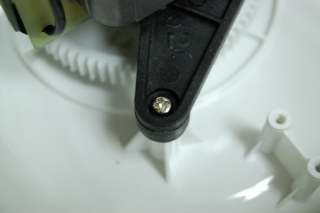
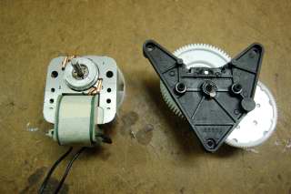
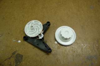
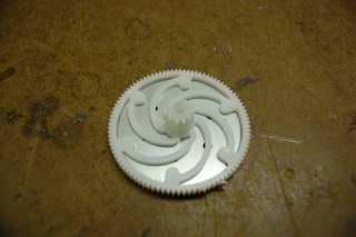
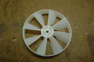
| - | '''Gear Assembly''' – The gear assembly consists of two main parts, one which contains a large gear attached to a small gear and is in mesh with the actual motor, and another which meshes in the small gear from the first part and connects to the mixing bowl. Both gears are mounted onto a plastic base which is also manufactured through injection molding. The fan can also be discussed in this section since it is attached to the motor. It appears that both the gear assembly and the fan are manufactured through injection molding for reproducibility and the low cost of materials. Because injection molding is a fairly simple but precise process, the gears can be manufactured quite easily and still be exact enough so that they mesh together well. <br />
| + | |
| - | ''Possible Alternatives'' - The only improvement our group considered to make the gear assembly easier to manufacture was to make both gears of the assembly identical so that only one mold would have to be used. This would lower manufacturing costs for the gears but another part would likely have to be designed and manufactured to connect to the mixing bowl so this benefit would be cancelled out. <br /> <br />
| + | |
| - | | + | |
| - | '''Motor Housing''' – The housing for the motor is made up of several (50) thin sheets of metal, possibly aluminum, that were manufactured using some sort of stamping process and then pressed together to form a thick solid piece. From a manufacturing standpoint, this is a clever design because stamping processes are relatively cheap and easy to use for mass producing products. However, because there are 50 different sheets that make up the housing, this creates complications from an assembly standpoint. <br />
| + | |
| - | ''Possible Alternatives'' – Alternatives to manufacturing the motor housing include molding the main part and then using a milling process to make the grooves. However, this is a much slower and more complicated method even though it saves time in the assembly process.<br /> <br />
| + | |
| - | | + | |
| - | '''Base, Lid, Mixing Arm, and Mixing Bowl''' – Both the base and lid are made of plastic so it is very likely that they were manufactured using a two part molding process. Since the base and lid serve no purpose other than being able to contain the other parts of the ice cream maker, they do not need to be overly precise can have a pretty wide tolerance so the molding process was used to save cost. The mixing arm and mixing bowl can also be discussed here since they are also made using a molding process. Although the mixing arm needs to be relatively precise, it is a simple design with no small grooves or difficult geometry and is made of plastic, so the molding process works well for this part also. The mixing bowl has three main parts, a plastic exterior, an aluminum interior, and a liquid component between the two parts that is used as insulation to keep heat out from the aluminum component. The plastic part was manufactured through the injection molding process and the aluminum bowl was manufactured through deep drawing. <br />
| + | |
| - | ''Possible Alternatives'' – The molding process is the best case to manufacture these parts since close precision is not necessary, the parts have a simple design (no difficult geometries involved) and a large amount of material (plastic/aluminum) goes into making these parts. There are no feasible alternatives that we could come up with.
| + | |
| - | | + | |
| - | ==Design for Assembly (DFA)==
| + | |
| - | A design for assembly analysis discusses how each component of the ice cream maker was assembled and seeks to minimize the time and cost associated with assembling the product into its final form. Below, the analysis is broken down into the components of the ice cream maker that were assembled.
| + | |
| - | | + | |
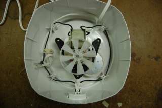
| - | '''Gear Assembly''' – The gear assembly is mounted to a base plate (See Part 7 of component list) using two shafts and the base plate is then affixed to the base of the ice cream maker using three identical screws. The only assembly required is that the metal shafts that the gears spin on must be attached to the plastic base and that entire gear assembly must be screwed into the base of the ice cream maker. <br />
| + | |
| - | ''Possible Alternatives'' – We could reduce the assembly time required to attach the metal shafts by making the entire base out of one part rather than three (two metal shafts and the plastic component). This would mean that the metal shafts would be made of plastic and the entire shaft/base assembly would be molded together. Also, the number of screws could possibly be reduced to two or metal fasteners could be used to make the assembly easier, saving time. The biggest drawback to both of these alternatives is that the product would probably be slightly more inclined to fail at this location.<br /><br />
| + | |
| - | | + | |
| - | '''Motor Housing''' – The motor housing is probably the most difficult part of the ice cream to assemble since it involves pressing together 50 separate thin sheets of metal. However, there are large benefits to using a stamping process as far the DFM analysis goes. Also, it is likely that an automated procedure is used to press together the sheets of the housing so the time associated with assembly is not as great as if a manual procedure was used. <br />
| + | |
| - | ''Possible Alternatives'' – Considering this piece from a DFMA standpoint (both manufacturing and assembly costs are considered), the best method is likely the one being used. Although the automated procedure to press together the sheets costs money, it is a fixed cost that does not vary with the number of housing pieces produced. There is little cost associated with time since an automated procedure is used. Therefore, the difficulty in assembling this part is acceptable since there are benefits to manufacturing it this way and time cost of assembly is small.<br /><br />
| + | |
| - | | + | |
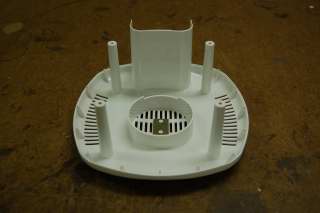
| - | '''Base, Lid, Mixing Arm, and Mixing Bowl''' – The lid and mixing arm have no assembly required since they consist of just one part so this discussion will be limited to the base and the mixing bowl. <br />
| + | |
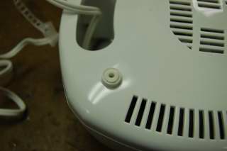
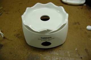
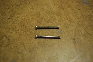
| - | '''Base''' - The base consists of two parts, which are screwed together using four screws. Three of the screws are identical Phillips head screws, while the fourth is manufactured with a button on the head of the screw such that it is very difficult to remove and probably also to screw in during assembly. A likely reason for this is that the manufacturer did want the user to take apart the base, primarily due to a safety standpoint. Also, it is likely that the manufacturer did want this ice cream maker to be opened up and be stripped for parts that could be sold individually. For this reason, they designed the fourth screw to be difficult to maneuver even though it is associated with a significantly longer assembly time. <br />
| + | |
| - | ''Possible Alternatives'' – The biggest improvement would be simply to make all four screws the same Phillips head screw. However, the designer quite deliberately designed the fourth screw with a button for the reasons outlined above. Therefore, considering the intentions of the manufacturer, the only possible alternatives would be to reduce the number of screws or to use metal fasteners or simply allow the base to press together by having plastic ridges that temporarily deform enough to allow the base to fit when pressed (similar to how the battery cap on a remote control fits on). With either of these alternatives, it is assumed that the button screw would still be used in addition in order to prevent the base from being opened easily. <br />
| + | |
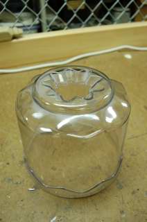
| - | '''Mixing Bowl''' - The mixing bowl assembly consists of pressing the aluminum interior to the plastic exterior and adhering the two pieces together at the bottom. A liquid component that is likely contained in a bag is also inserted between the aluminum and the plastic. <br />
| + | |
| - | ''Possible Alternatives'' – This is a fairly easily assembly process consisting of three components. It is clever in that the aluminum simple adheres to the plastic exterior rather than using screws or fasteners which could upset the geometry of the interior of the mixing bowl and would likely take more assembly time. There are no feasible alternatives to assembly that would save time or cost.
| + | |
| - | | + | |
| - | =Failure Mode and Effects Analysis (FMEA)=
| + | |
| - | | + | |
| - | This chart shows the top failure modes of the ice cream/sorbet maker. This is a risk assessment of the major parts of the device and how each failure ranks on a priority list. The failures are recorded in a few categories, which are severity, occurrence, and detection. The severity of the failure is a value that represents how crucial this part or action is to the usage of the product. The occurrence represents how often the failure occurs per 10,000 products. The detection represents how easily the failure mode can be detected, either in the assembly line process or by the user. Here is our FMEA of our ice cream maker. After the table, some of the values will be explained in further detail.
| + | |
| - | | + | |
| - | | + | |
| - | {| class="wikitable" border="1"
| + | |
| - | |- align="center"
| + | |
| - | ! Item & Function !! Failure Mode !! Effects of Failure !! S !! Causes of Failure !! O !! Design Controls !! D !! RPN !! Recommended Actions !! Responsibility & Deadline !! Actions Taken !! S<sup>*</sup> !! O<sup>*</sup> !! D<sup>*</sup> !! RPN<sup>*</sup>
| + | |
| - | |-
| + | |
| - | |- align="left"
| + | |
| - | | rowspan=2 | Motor
| + | |
| - | * Powers the gear train
| + | |
| - | | Electrical failures: Motor may overheat and fail
| + | |
| - | | Product will not mix the ice cream, and the product may not have good consistency.
| + | |
| - | | 8 || Motor may overheat when the ice cream starts solidifying. The increased viscosity of the ice cream may add too much torque on the motor. || 6 || Testing with different types of ice cream and find the point when the load applied is too high || 5 || 240 || Find a controller that will turn off the motor once the torque applied to the motor gets too high || Motor Manufacturer || Integrate a current sensor into the design || 8 || 1 || 5 || 40
| + | |
| - | |-
| + | |
| - | | Mechanical Failure: Gear train may strip
| + | |
| - | | The rotation of the motor will not be transferred to the product || 8 || The increased friction in between the separate gears can cause the gears to strip || 2 || Testing the durability of the gears || 4 || 48 || Test different materials to find the most cost-effective solution|| Gear Manufacturer || N/A || 8 || 2 || 4 || 48
| + | |
| - | | + | |
| - | |- align="left"
| + | |
| - | | Mixing Arm
| + | |
| - | * Plastic piece that mixes the contents of the bowl
| + | |
| - | | Mixing arm breaks/fails
| + | |
| - | | Contents of the bowl will not be properly mixed to form a consistent product.
| + | |
| - | | 6 || The increased viscosity of the product may cause the mixing arm to break. || 3 || Test to see the breaking point of the mixing arm. || 1 || 18 || Test different materials to find the most cost-effective solution || Manufacturer || N/A || 6 || 3 || 1 || 18
| + | |
| - | | + | |
| - | |- align="left"
| + | |
| - | | Wiring
| + | |
| - | * Transmits the current from the outlet to the device
| + | |
| - | | Current does not get transferred from the power outlet to the motor
| + | |
| - | | Motor will not rotate the bowl, so contents of bowl will not get mixed.
| + | |
| - | | 8 || The increased viscosity of the product may cause the mixing arm to break. || 2 || Before final assembly of the product, test connection points to see if all wiring points are valid || 3 || 48 || Install a station in the assembly process to make sure that all wiring connections are good || Assemblerer || N/A || 8 || 2 || 3 || 48
| + | |
| - | | + | |
| - | | + | |
| - | |- align="left"
| + | |
| - | | Switch
| + | |
| - | * Switch allows the current to pass from the power source to the motor
| + | |
| - | | Switch does not allow current to pass through
| + | |
| - | | Motor will not rotate the bowl, so contents of bowl will not get mixed.
| + | |
| - | | 8 || The switch connection may not contact the part that is used to close the circuit || 2 || Test to see if connection points are durable after many clicks (turn on and off many times) || 3 || 48 || Test a switch for 1,000 times to see if the switch operates properly each time || Assemblerer || N/A || 8 || 2 || 3 || 48
| + | |
| - | | + | |
| - | |}
| + | |
| - | | + | |
| - | The Failure Mode Effects and Analysis of this particular ice cream maker is based on the intended use of the maker. The rankings that were assigned represent how valuable each operation is to the overall function of the device. Although the design of the product is very simple, if these items were to fail, it would result in loss of function for the device.
| + | |
| - | | + | |
| - | The motor failure is classified as a severity of 8 because the criteria of 8 represents that "Item inoperable, with loss of primary function." Since the function of the ice cream maker is to mix the contents of the bowl, if the motor is not working, then the primary function of the device is lost. If the failure mode results in the loss of bowl rotation, then the product has lost its primary function and can no longer be used. The failure of the mixing arm was categorized as a 6 because the customer would have some dissatisfaction that the product can no longer be used properly, but the product could still be utilized to make ice cream. As you can see, the electrical failure of the motor has the highest RPN (Risk Priority Number), which means that this item and function has the highest probability of failing.
| + | |
| - | | + | |
| - | For the rest of the device, the occurrence and detection values are low because there is low complexity in the design. If there was a faulty connection, it would most likely be noticed in the assembly process. After reviewing customer reviews on amazon.com, we found that there were some customer complaints about motor failure and how ineffective the product was. Although this was not the best way to determine the occurrence and detection values, it was the best source of data that could be found on our product.
| + | |
| - | | + | |
| - | = Ice cream maker DFE =
| + | |
| - | | + | |
| - | This section examines the environmental impact of the [[ice cream maker]] from each stage through the manufacturing process through disposal of the product.
| + | |
| - | | + | |
| - | == Life Cycle Assessment ==
| + | |
| - | | + | |
| - | A Life Cycle Assessment ([[LCA]]) accounts for the total environmental impact of the product. The manufacturing and usage of the product have inputs from different economic sectors. An Economic Input-Output LCA ([[EIO-LCA]]) analyzes these inputs to the system. All data from this EIO-LCA is from 1997 and available from the LAC software at http://www.eiolca.net and the Bureau of Economic Analysis at http://bea.gov.
| + | |
| - | | + | |
| - | The Ice cream maker best fits into the "Electric housewares and household fan manufacturing" sector. This appliance is different from commercial ice cream makers because it does not have a large refrigerator component. When assembling an ice cream maker of this magnitude, the assembly process is similar to a food processor or a blender. In this sector, the majority of the appliances that are represented are electric fans and different types of small cooking appliances, which are assembled similarly. The only difference between the mechanical aspects of an electrical fan and our ice cream maker is that there is a gear assembly that increases torque and slows down the rotational velocity.
| + | |
| - | | + | |
| - | == Production ==
| + | |
| - | The energy cost of production of $1 million worth of Ice Cream Makers is 0.503 MkWh (million kilowatt hours).
| + | |
| - | | + | |
| - | The top sectors responsible for producing '''greenhouse gases''' related to ice cream maker manufacturing are:
| + | |
| - | | + | |
| - | <blockquote>Power generation and supply<br />
| + | |
| - | Truck transportation<br />
| + | |
| - | Iron and steel mills<br />
| + | |
| - | Electric housewares and household fan manufacturing,<br />
| + | |
| - | Waste management and remediation services<br />
| + | |
| - | Primary aluminum production<br />
| + | |
| - | Paper and paperboard mills<br />
| + | |
| - | Oil and gas extraction<br />
| + | |
| - | Plastics material and resin manufacturing<br/>
| + | |
| - | Other nonmetallic mineral mining</blockquote>
| + | |
| - | | + | |
| - | | + | |
| - | {| class="wikitable" border="1"
| + | |
| - | |-
| + | |
| - | ! Emissions !! GWP<br />MTCO2E !! CO2<br />MTCO2E !! CH4<br/>MTCO2E !! N2O<br />MTCO2E !! CFCs<br />MTCO2E
| + | |
| - | |-
| + | |
| - | ! Total for all Sectors
| + | |
| - | | 693. || 598. || 54.1 || 10.7 || 30.5
| + | |
| - | |}
| + | |
| - | | + | |
| - | The top sectors responsible for producing '''toxic waste''' related to ice cream maker manufacturing are:
| + | |
| - | <blockquote>Electric housewares and household fan manufacturing<br />
| + | |
| - | Plastics material and resin manufacturing<br />
| + | |
| - | Plastics plumbing fixtures and all other plastics products<br />
| + | |
| - | Other basic organic chemical manufacturing<br />
| + | |
| - | Primary aluminum production</blockquote>
| + | |
| - | | + | |
| - | The components of the ice cream maker that are most conducive to toxic waste production are the parts made of plastic (the gears, housing, lid, mixing arm). Another component that adds to the toxic waste production are the parts made of aluminum.
| + | |
| - | | + | |
| - | == Transportation ==
| + | |
| - | | + | |
| - | The mode of shipment of this product is primary through ground shipping, which is a major contributer to greenhouse gas emissions. If you switch over to a purchaser price model of the production system, this causes a 45.9% increase in the economic activity for the truck transportation sector. This increase is due to shipping after production, which is the emissions of the trucks from the manufacturer to the retail location. When this shipping is considered, the GWP emissions increase only by 30 CO2 equivalents. This amount is insignificant compared to the total GWP emissions, which is about 600 CO2 equivalents.
| + | |
| - | | + | |
| - | == Use ==
| + | |
| - | | + | |
| - | Our ice cream maker uses a 50 W motor, and on average, is used for 20-30 minutes per cycle. Depending on the consumer, the number of uses within the products lifetime will vary greatly. Since our Cuisinart Frozen Yogurt/Ice Cream/Sorbet maker is covered by a three year limited warranty, a conservative lifespan estimate may be about three or four times that length. <br /><br />
| + | |
| - | | + | |
| - | If a consumer makes ice cream twice a month for roughly ten years, assuming the product is used in a conventional manner, the machine will run for eight hours a year and 80 hours over its lifetime. A simple calculation reviels that the ice cream maker will use around 4.0 kilowatt hours of electricty over its lifetime. <br /><br />
| + | |
| - | | + | |
| - | According to the Energy Information Administrations (http://eia.doe.gov) for 1997, the average price of 1 KwH in Pennsylvania was 10.07 cents. Assuming that the user commits 4.0 KwH to runnig the ice cream maker, the consumer will have to pay about $0.40 extra in electricity.
| + | |
| - | | + | |
| - | Since 1997, there has been 27.23% inflation rate according to http://inflationdata.com. This means that a $50 ice cream maker in 2007 is equivalent to a $40 ice cream maker in 1997. Based on these numbers (in 1997 based dollars) it is estimated that a million dollars of ice cream makers would cost about $10,500 in electricity use.
| + | |
| - | | + | |
| - | | + | |
| - | {| class="wikitable" border="1"
| + | |
| - | |-
| + | |
| - | ! Emissions<br />from Electricity Use !! GWP<br />MTCO2E !! CO2<br />MTCO2E !! CH4<br/>MTCO2E !! N2O<br />MTCO2E !! CFCs<br />MTCO2E
| + | |
| - | |-
| + | |
| - | ! Total for all Sectors
| + | |
| - | | 110 || 105|| 3.95 || 0.053 || 1.29
| + | |
| - | |}
| + | |
| - | | + | |
| - | == LCA Conclusions ==
| + | |
| - | | + | |
| - | This LCA is a rough estimate of the impact of the ice cream maker. The following possibilities emerge as sources for a more environmentally friendly design
| + | |
| - | * Redesign processes in the manufacturing and assembly stages to reduce the usage of electricity. The manufacturing stage is where the greatest amount of electricity is being consumed. If you introduced new techniques into the design, such as assembling plastic-hook fasteners instead of screws, you may get rid of some use of electrical tools.
| + | |
| - | * Redesign the base of the product. When opening the base, there was a lot of excess room. If we could redesign the product so that the base is more compact, this can reduce the amount of toxic waste that the manufacturing plant produces.
| + | |
| - | * Introduce an optional hand crank into the process. If the consumer is willing to operate the product with their own energy, this would reduce the consumption of electricity, which would reduce the greenhouse gas emissions from the electricity plant.
| + | |
| - | | + | |
| - | Using the LCA, there is a level of uncertainty in the data because the household ice cream maker is not specifically listed in any of the sectors. The sector that best fits our product is "Electric housewares and household fan manufacturing" because the mechanical elements are similar. Although this is the best fit to our product, there are still limitations to using this approximation because our products do not use heating elements and uses very little iron or steel in its design. The LCA data is good enough to produce a rough estimate for what we are looking for.
| + | |
| - | | + | |
| - | =Mechanical Analysis=
| + | |
| - | | + | |
| - | A mechanical analysis of the gear box used to torque up the motor is considered in this section. The given data is the number of teeth on each of the three gears (<math>N_1, N_2</math>, and <math>N_3</math>) and the motor shaft (<math>N_{motor}</math>). Also given is the final angular velocity of the mixing bowl, and thus gear 1 (<math>\omega_1</math>) since the two are attached. From this, we can find the torque provided by the motor (<math>\tau_{motor}</math>) and the angular velocity of the motor shaft (<math>\omega_{motor}</math>). The picture below shows the gear box with each gear labeled. Gears 2 and 3 are affixed to each other so that each has the same angular velocity and gear 1 is attached directly to the mixing bowl (not pictured).
| + | |
| - | <br />
| + | |
| - | [[Image:IC Gear Diagram.JPG]]
| + | |
| - | | + | |
| - | '''Given''' <br />
| + | |
| - | <math>\omega_1\approx</math> 60 rpm <br />
| + | |
| - | <math>N_1</math> = 75 teeth <br />
| + | |
| - | <math>N_2</math> = 11 teeth <br />
| + | |
| - | <math>N_3</math> = 95 teeth <br />
| + | |
| - | <math>N_{motor}</math> = 7 teeth <br /><br />
| + | |
| - | | + | |
| - | '''Calculations:''' <br />
| + | |
| - | | + | |
| - | <math>\omega_2 = \omega_1\times\frac{N_1}{N_2} = 60</math>rpm <math>\times\frac{75}{11} = 409.09</math> rpm <br />
| + | |
| - | | + | |
| - | Because gear 2 and gear 3 are joined together, the relationship <math>\omega_2 = \omega_3</math> holds true. Gear 3 is in mesh with the motor, so we can find <math>\omega_{motor}</math> as shown below.
| + | |
| - | | + | |
| - | <math>\omega_{motor} = \omega_3\times\frac{N_3}{N_{motor}} = 409.09</math>rpm <math>\times\frac{95}{7} = 5551.95</math> rpm <br />
| + | |
| - | <math>\omega_{motor}(rad/s) = \omega_{motor}(rpm)\times\frac{2\pi}{60s}=581.40\frac{rad}{s}</math> <br />
| + | |
| - | <math>P = \tau\cdot\omega_{motor}\rightarrow\tau=\frac{P}{\omega_{motor}}</math> , '''''P = 50W is labeled on the box''''' <br />
| + | |
| - | <math>\tau_{motor}=\frac{50 W}{581.40 rad/s} = .086</math>N-m
| + | |
| - | <br /> <br />
| + | |
| - | | + | |
| - | Calculations of the torque and angular velocity of the motor are important so that we can consider using alternate motors in order to reduce cost. The biggest reason that a low torque motor was used in conjuction with a gear box instead of just using a higher torque motor is that higher torque motors usually are larger and more expensive. However, with this mechanical analysis, we may be able to find some middle ground where the cost can be reduced by changing to a slightly higher torque motor and perhaps eliminating parts of the gear box. We can also consider doing the converse of this, and using an even lower torque motor and experimenting with different gear ratios.
| + | |
| - | | + | |
| - | = How the ice cream maker is used =
| + | |
| - | This section shows a flow chart that describes how the product is used:
| + | |
| - | | + | |
| - | [[Image:IceCreamMakerOperation.gif]]
| + | |
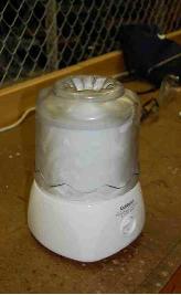
An ice cream maker is a household appliance where the consumer can custom make their own ice cream, sorbet, or other frozen desserts. It provides a simple solution to those consumers who want to make up to 1-1/2 quarts of ice cream. This automated machine is a convenient replacement for the manual method of making your own ice cream, through the use of salt and ice.
The way that this machine works is with an AC motor that turns the pre-frozen bowl around the mixing arm to mix the contents of the bowl. Although this is a very simple design, through product analysis, we are seeking areas for improvement. The primary goal of our analysis is to assess the current design of the ice cream maker through product disassembly and to identify possible areas for improvement. Tools that were used to aid us in our analysis included Design for Manufacture and Assembly (DFMA), Failure Mode Effects and Analysis (FMEA), Design for Environment (DFE), and Life Cycle Assesment (LCA).
The main conclusions to be obtained from the DFMA analysis were that it appeared as if many or all of the components were designed with design for manufacture (DFM) in mind, and any possible DFM improvement had a negative tradeoff associated with it. From an assembly or DFA standpoint, several possible alternatives were considered to reduce the number of parts and thus assembly time. The most significant of these alternatives were to design the gear box base as one piece or to use fasteners instead of screws to assemble the base together.
The FMEA analysis showed that the motor failure will cause the consumer the most dissatisfaction. Since the function of the ice cream maker is to mix the contents of the bowl, if the motor is not working, then the primary function of the device is lost. Other possible significant failures include switch malfunction, which will result in the same customer dissatisfaction.
An LCA analysis gave us an estimate of the environmental repercussions of manufacturing, usage, and disposal of the ice cream maker. Our data analysis came from eiolca.net, which uses economic and environmental data from 1997. It was found that most of the emissions came from the manufacturing of the product, primarily from the plastic parts. Other stages of the products life, such as shipment, use, and disposal of the good were considered in our analysis, but did not have nearly as much of an environmental impact.
Furthermore, we studied the gear train, which converts the torque from the motor to the angular velocity of the mixing bowl. This means that we can convert the high speed motor to a lower speed that has a greater ability to stir denser mixtures in the bowl. Our mechanical analysis allowed us to consider why a low torque motor in conjunction with a gear assembly was chosen instead of a high torque motor. We concluded that the two main reasons for this design was for cost and size constraints.
Customers who purchase the Cuisinart Ice Cream Maker do so for the purpose of making frozen desserts in the confines of their home. The dessert maker is capable of making frozen yogurt, ice cream, and sorbet. Included with the ice cream maker is an instruction and recipe booklet that describes to users how to make all the various frozen desserts listed as the primary functions. Additionally, the ice cream maker is capable of making dessert drinks such as slushies and frozen drinks such as pina coladas and daiquiris.
Some of the basic customer needs are to provide them with a machine that will produce their desired product in an efficient manner. These needs can be categorized into some sub-categories:
