Ice cream maker
From DDL Wiki
Contents |
Executive Summary
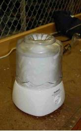
An ice cream maker is a household appliance where the consumer can custom make their own ice cream, sorbet, or other frozen desserts. It provides a simple solution to those consumers who want to make up to 1-1/2 quarts of ice cream. This automated machine is a convenient replacement for the manual method of making your own ice cream, through the use of salt and ice.
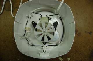
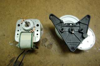
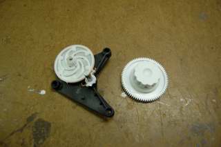
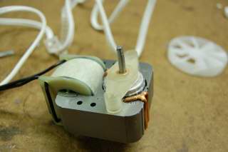
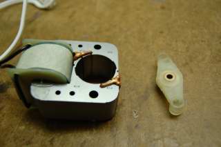
The way that this machine works is with an AC motor that turns the pre-frozen bowl around the mixing arm to mix the contents of the bowl. Although this is a very simple design, through product analysis, we are seeking areas for improvement. The primary goal of our analysis is to assess the current design of the ice cream maker through product disassembly and to identify possible areas for improvement. Tools that were used to aid us in our analysis included Design for Manufacture and Assembly (DFMA), Failure Mode Effects and Analysis (FMEA), Design for Environment (DFE), and Life Cycle Assesment (LCA).
The main conclusions to be obtained from the DFMA analysis were that it appeared as if many or all of the components were designed with design for manufacture (DFM) in mind, and any possible DFM improvement had a negative tradeoff associated with it. From an assembly or DFA standpoint, several possible alternatives were considered to reduce the number of parts and thus assembly time. The most significant of these alternatives were to design the gear box base as one piece or to use fasteners instead of screws to assemble the base together.
The FMEA analysis showed that the motor failure will cause the consumer the most dissatisfaction. Since the function of the ice cream maker is to mix the contents of the bowl, if the motor is not working, then the primary function of the device is lost. Other possible significant failures include switch malfunction, which will result in the same customer dissatisfaction.
An LCA analysis gave us an estimate of the environmental repercussions of manufacturing, usage, and disposal of the ice cream maker. Our data analysis came from eiolca.net, which uses economic and environmental data from 1997. It was found that most of the emissions came from the manufacturing of the product, primarily from the plastic parts. Other stages of the products life, such as shipment, use, and disposal of the good were considered in our analysis, but did not have nearly as much of an environmental impact.
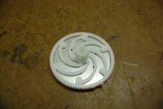
Furthermore, we studied the gear train, which converts the torque from the motor to the angular velocity of the mixing bowl. This means that we can convert the high speed motor to a lower speed that has a greater ability to stir denser mixtures in the bowl. Our mechanical analysis allowed us to consider why a low torque motor in conjunction with a gear assembly was chosen instead of a high torque motor. We concluded that the two main reasons for this design was for cost and size constraints.
Customer Needs
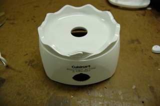
Customers who purchase the Cuisinart Ice Cream Maker do so for the purpose of making frozen desserts in the confines of their home. The dessert maker is capable of making frozen yogurt, ice cream, and sorbet. Included with the ice cream maker is an instruction and recipe booklet that describes to users how to make all the various frozen desserts listed as the primary functions. Additionally, the ice cream maker is capable of making dessert drinks such as slushies and frozen drinks such as pina coladas and daiquiris.
Some of the basic customer needs are to provide them with a machine that will produce their desired product in an efficient manner. These needs can be categorized into some sub-categories:
- Efficiently: produce made from start to finish in about a half hour
- Quietly: machine runs quietly when plugged in and product is being made
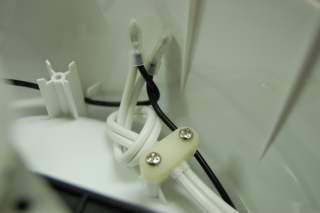
- Safely: all electrical connections of the device are done in a way to reduce or eliminate any serious failure modes
