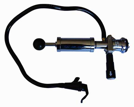
Keg tap
From DDL Wiki
Contents |
Executive Summary
- Describes key findings and recommendations
Major Stakeholders and Product Needs
- Identify major post-production stakeholders and list major product needs for each
Usage
- Document in detail how the product is used, step by step, and summarize findings from your user studies.
Bill of Materials
- Also identify standard purchase parts.
Keg Tap Components
Assembly Diagrams
- Include pictures of the assembly with all components labeled
Mechanical Function
- Document how the system functions mechanically
Design for Manufacturing and Assembly (DFMA)
- Highlight findings and opportunities for improvement, indentifying where our competitor has followed guidelines and made good choices.
- In particular, are there opportunities to improve manufacturability and make a competing product cheaper? Identify where material and process choices are appropriate or inappropriate for expected production volume.
Failure Modes and Effects Analysis (FMEA)
- Highlight findings and opportunities for improvement, indentifying where our competitor has followed guidelines and made good choices.
- In particular, are there important failure modes that should be considered in a redesign or a new design? Focus on use phase, rather than manufacturing.
| Part # | Item | Function | Failure Mode | Effects of Failure | S | Cause of Failure | O | Design Controls | D | RPN | Recommended Actions |
|---|---|---|---|---|---|---|---|---|---|---|---|
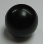
| 1 | Black Ball | Grip for Pumping | *Could be Unscrewed and Lost | Uncomfortable Pumping | Unaware Users | cell 8 | cell 9 | cell 10 | cell 11 | ||
| 2 | Plunger | Forces Air into Keg | cell 3 | cell 4 | cell 6 | cell 8 | cell 9 | cell 10 | cell 11 | ||
| 3 | Plunger Ring | Air Tight | cell 3 | cell 4 | cell 6 | cell 8 | cell 9 | cell 10 | cell 11 | ||
| 3.1 | O-Ring | Seal | cell 3 | cell 4 | cell 6 | cell 8 | cell 9 | cell 10 | cell 11 | ||
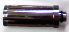
| 4 | Cylindrical Plunger Casing | Supply Keg with Pressure | cell 3 | cell 4 | cell 6 | cell 8 | cell 9 | cell 10 | cell 11 | ||
| 5 | Cylindrical Top | Encloses Plunger in Casing | cell 3 | cell 4 | cell 6 | cell 8 | cell 9 | cell 10 | cell 11 | ||
| 6 | Spring | Prevents Plunger from Getting Stuck | cell 3 | cell 4 | cell 6 | cell 8 | cell 9 | cell 10 | cell 11 | ||
| 7 | Center Cylinder | Separates Air Input from Beer Output | cell 3 | cell 4 | cell 6 | cell 8 | cell 9 | cell 10 | cell 11 | ||
| 7.1 | O-Ring | Seal | cell 3 | cell 4 | cell 6 | cell 8 | cell 9 | cell 10 | cell 11 | ||
| 8 | Lever | Attaches Tap and Keg | cell 3 | cell 4 | cell 6 | cell 8 | cell 9 | cell 10 | cell 11 | ||
| 8.1 | Plastic Casing | cell 2 | cell 3 | cell 4 | cell 6 | cell 8 | cell 9 | cell 10 | cell 11 | ||
| 8.2 | White Cap | cell 2 | cell 3 | cell 4 | cell 6 | cell 8 | cell 9 | cell 10 | cell 11 | ||
| 8.3 | Spring | cell 2 | cell 3 | cell 4 | cell 6 | cell 8 | cell 9 | cell 10 | cell 11 | ||
| 8.4 | Center Rod | cell 2 | cell 3 | cell 4 | cell 6 | cell 8 | cell 9 | cell 10 | cell 11 | ||
| 8.5 | Nut | cell 2 | cell 3 | cell 4 | cell 6 | cell 8 | cell 9 | cell 10 | cell 11 | ||
| 8.6 | Washer | cell 2 | cell 3 | cell 4 | cell 6 | cell 8 | cell 9 | cell 10 | cell 11 | ||
| 9 | Lever Pin | cell 2 | cell 3 | cell 4 | cell 6 | cell 8 | cell 9 | cell 10 | cell 11 | ||
| 10 | Base | Attaches to Keg | cell 3 | cell 4 | cell 6 | cell 8 | cell 9 | cell 10 | cell 11 | ||
| 10.1 | O-Ring | Seal | cell 3 | cell 4 | cell 6 | cell 8 | cell 9 | cell 10 | cell 11 | ||
| 11 | Hose | Transfers Beer from Tap to Cup/Mouth | cell 3 | cell 4 | cell 6 | cell 8 | cell 9 | cell 10 | cell 11 | ||
| 12 | Nozzle | Releases Beer from Hose | cell 3 | cell 4 | cell 6 | cell 8 | cell 9 | cell 10 | cell 11 | ||
| 12.1 | Handle | cell 2 | cell 3 | cell 4 | cell 6 | cell 8 | cell 9 | cell 10 | cell 11 | ||
| 12.2 | White Plastic Center | cell 2 | cell 3 | cell 4 | cell 6 | cell 8 | cell 9 | cell 10 | cell 11 | ||
| 12.3 | Spring | cell 2 | cell 3 | cell 4 | cell 6 | cell 8 | cell 9 | cell 10 | cell 11 | ||
| 12.4 | Cap Seal | cell 2 | cell 3 | cell 4 | cell 6 | cell 8 | cell 9 | cell 10 | cell 11 | ||
| 12.5 | Hard Plastic Cap | cell 2 | cell 3 | cell 4 | cell 6 | cell 8 | cell 9 | cell 10 | cell 11
|
Design for Environment (DFE)
- Highlight findings and opportunities for improvement, indentifying where our competitor has followed guidelines and made good choices.
- In particular, if Congress were to pass a tax on CO2, would this have a significant impact on the cost of production or use of the product?
Mechanical Analysis
- Include mechanical analysis to support quantitative understanding of the product's most critical mechanical aspects. Indluce a free body diagram, and be sure to define all symbols and explain all equations used.
Team Member Roles
- Identify team member roles during this phase and summarize your process. Submit individual peer evaluations to Prof.
