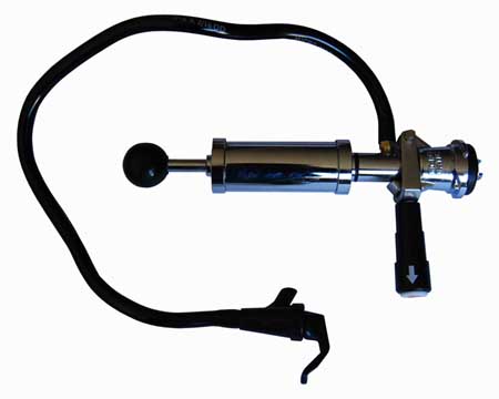
Keg tap
From DDL Wiki
Contents |
Executive Summary
- Describes key findings and recommendations
Major Stakeholders and Product Needs
- Identify major post-production stakeholders and list major product needs for each
Usage
- Document in detail how the product is used, step by step, and summarize findings from your user studies.
Bill of Materials
- Also identify standard purchase parts.
Keg Tap Components
| Part Number | Name | QTY | Weight (oz) | Function | Material | Manufacturing Process | Image |
|---|---|---|---|---|---|---|---|
| 1 | Black Ball | 1 | 1 | Grip for pumping | Plastic | Injection molding | |
| 2 | Plunger | 1 | 4.3 | Forces air into casing | Stainless Steel | Extrusion, machined threads | 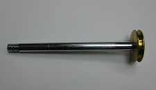
|
| 3.1 | O-ring | 1 | 0.05 | Seal | Rubber | Injection molding | |
| 4 | Cylindrical Plunger Casing | 1 | 6.3 | Pressure for pumping | Stainless Steel | Extrusion, machined threads | 
|
| 5 | Cylindrical Top | 1 | 1.7 | Encloses plunger in casing | Stainless Steel | Extrusion, lathe, machined threads | |
| 6 | Plunger spring | 1 | 0.1 | Prevents plunger from getting stuck | Stainless Steel | Extrusion, bending | Image:KegTap Spring.jpg |
| 7 | Center Cylinder | 1 | 6.8 | Separates air input from beer output | Stainless Steel | Extrusion, mill, lathe, drilled holes, machined threads | |
| 7.1 | O-ring | 1 | 0.05 | Seal | Rubber | Injection molding | |
| 8 | Lever | 1 | 4.1 | Attaches tap to keg | Steel | Cast, machined threads | -- |
| 8.1 | Lever Casing | 1 | 0.5 | Provides grip for user to pull lever up | Plastic | Injection molding | -- |
| 8.2 | White Cap | 1 | 0.1 | Prevents nut from potentially falling off | Plastic | Injection molding | |
| 8.3 | Lever spring | 1 | 0.1 | Provides compression that enables lever to lock in place | Stainless steel | Extrusion, bending | -- |
| 8.4 | Center Rod | 1 | 0.5 | Locks lever into machined groove on base | Brass? | -- | -- |
| 8.5 | Nut | 1 | 0.05 | -- | -- | -- | -- |
| 8.6 | Washer | 1 | 0.05 | -- | -- | -- | -- |
| 9 | Lever Pin | 1 | 0.2 | -- | -- | -- | 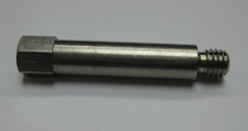
|
| 10 | Base | 1 | 7.2 | Attaches to keg | -- | -- | 
|
| 10.1 | O-ring | 1 | 0.1 | Seal | -- | -- | |
| 11 | Hose | 1 | 2.7 | Transfers beer from keg to cup | -- | -- | -- |
| 12 | Nozzle | 1 | 0.4 | Releases beer from hose | -- | -- | -- |
| 12.1 | Handle | 1 | -- | -- | -- | -- | -- |
| 12.2 | White Plastic Center | 1 | -- | -- | -- | -- | -- |
| 12.3 | Spring | 1 | -- | -- | -- | -- | -- |
| 12.4 | Cap Seal | 1 | -- | -- | -- | -- | |
| 12.5 | Hard Plastic Cap | 1 | -- | -- | -- | -- | -- |
Assembly Diagrams
- Include pictures of the assembly with all components labeled
Mechanical Function
- Document how the system functions mechanically
Design for Manufacturing and Assembly (DFMA)
- Highlight findings and opportunities for improvement, identifying where our competitor has followed guidelines and made good choices.
- In particular, are there opportunities to improve manufacturability and make a competing product cheaper? Identify where material and process choices are appropriate or inappropriate for expected production volume.
This particular keg tap consists of 26 distinct parts. The majority of the metal pieces are made from stainless steel, with the exception of three that are made from brass. All three of the brass pieces are interior components. The non-metal components are made from plastic and rubber.
This keg tap was manufactured with a low to medium volume production in mind. For a larger production volume, the manufacturing would need a complete overhaul. Sand casting is suitable for medium volume production.
All of the metal components are shaped using a deformation process except for the base, which is sand cast. Sand casting is a logical manufacturing choice for this piece because of its relatively complex shape. The other metal parts are extruded
Stainless steel parts extruded, then subtractive manufacturing processes applied. Lots of machining involved, making it a more expensive product. More expensive because it takes more time and wastes material (drilling holes, shaping).
All parts are joined by threads or snapped on (o-rings). This saves machine cost in manufacturing, but may take more time (most likely assembled by hand in an assembly line). Joining method good for the consumer because you can take the tap apart to clean it; also replace parts if need be. A common failure mode may be o-ring fatigue; these parts could easily be replaced instead of buying a new tap.
DFM minimize part count standardize components standardize design features keep design simple multifunctional parts ease of fabrication avoid tight tolerances minimize secondary & finishing operations
DFA minimize part count minimize assembly surfaces mistake-proof minimize fasteners
Failure Modes and Effects Analysis (FMEA)
- Highlight findings and opportunities for improvement, indentifying where our competitor has followed guidelines and made good choices.
- In particular, are there important failure modes that should be considered in a redesign or a new design? Focus on use phase, rather than manufacturing.
| Part # | Item | Function | Failure Mode | Effects of Failure | S | Cause of Failure | O | Design Controls | D | RPN | Recommended Actions |
|---|---|---|---|---|---|---|---|---|---|---|---|
| 1 | Black Ball | Grip for Pumping | Could be Unscrewed and Lost | Uncomfortable Pumping | Unaware Users | Make sure the ball is screwed on tightly | Apply Loctite | ||||
| 2 | Plunger | Forces Air into Keg | This part is very robust. Cannot foresee any failure modes. | ||||||||
| 3 | Plunger Disc | Air Tight | This part is very robust. Cannot foresee any failure modes. | ||||||||
| 3.1 | O-Ring | Seal | O-ring becomes hardened | Loss of air tight seal for pressurizing keg | Repeated use and time | Oil the o-ring to keep it moist | Sell spare parts | ||||
| 4 | Cylindrical Plunger Casing | Supply Keg with Pressure | Dent in the casing, burs, scratches, rust on the inside of the casing | Plunger cannot be moved inside the case, o-ring gets torn up | Misuse, Dropping the tap | All these pieces are robust | None | ||||
| 5 | Cylindrical Top | Encloses Plunger in Casing | Top comes unscrewed | Cannot pressurize keg | Human tampering | Screwed on tightly | None, gluing these threads makes disassembly harder | ||||
| 6 | Spring | Prevents Plunger from Getting Stuck | Breaks | Plunger, though unlikely, may get stuck at top of casing | Misuse or fatigue | Robust spring | Sell spare parts | ||||
| 7 | Center Cylinder | Separates Air Input from Beer Output | 1)Leaks beer at the connection point with hose
2)Creates turbulence in beer flow | 1)Loss of beer
2)Foamy beer | 1)Sealant on threads is old
2)Manufacturing | 1)Sealant is used
2)Their Design | 1)None
2)Look into smoother way to transition into tubing | ||||
| 7.1 | O-Ring | Seal | O-ring becomes hardened | Loss of air tight seal for pressurizing keg | Repeated use and time | Oil the o-ring to keep it moist | Sell spare parts | ||||
| 8 | Lever | Attaches Tap and Keg allowing the flow of beer | This part is very robust. Cannot foresee any failure modes. | ||||||||
| 8.1 | Plastic Casing | Grip for user | Breaks | Unable to attach tap to keg | Ridiculous Misuse | Very strong part | None | ||||
| 8.2 | White Cap | Aesthetics | Could break or get lost | None | Misuse or overuse | Tight fit keeps it in place | None | ||||
| 8.3 | Spring | Helps lock tap in two certain positions | Impact fatigue | Unable to lock tap into open position on keg | User misuse | Robust spring | Brainstorm new ways to lock tap | ||||
| 8.4 | Center Rod | Helps hold handle together | This part is very robust. Cannot foresee any failure modes. | ||||||||
| 8.5 | Nut | Helps hold handle together | Could come unscrewed | Unable to use tap | Repeated use | Make sure it is screwed on the whole way | None | ||||
| 8.6 | Washer | Helps hold handle together | Cannot foresee any failure modes | ||||||||
| 9 | Lever Pin | Attaches the lever to the base and acts as a pivot point for the lever | No foreseen failure modes. | ||||||||
| 10 | Base | Attaches to Keg | Threads become crooked | Unable to connect tap to keg | Terrible misuse | Threads are robust | Sell spare parts | ||||
| 10.1 | O-Ring | Seal | O-ring becomes hardened | Loss of air tight seal for pressurizing keg | Repeated use and time | Oil the o-ring to keep it moist | Sell spare parts | ||||
| 11 | Hose | Transfers Beer from Tap to Cup/Mouth | 1)Hole
2)Kink | 1)Beer is lost
2)Beer cannot reach its destination | 1)Not taking care of tap
2)Jokes | Thick tubing | None | ||||
| 12 | Nozzle | Releases Beer from Hose | cell 3 | cell 4 | cell 6 | cell 8 | cell 9 | cell 10 | cell 11 | ||
| 12.1 | Handle | cell 2 | cell 3 | cell 4 | cell 6 | cell 8 | cell 9 | cell 10 | cell 11 | ||
| 12.2 | White Plastic Center | cell 2 | cell 3 | cell 4 | cell 6 | cell 8 | cell 9 | cell 10 | cell 11 | ||
| 12.3 | Spring | cell 2 | cell 3 | cell 4 | cell 6 | cell 8 | cell 9 | cell 10 | cell 11 | ||
| 12.4 | Cap Seal | cell 2 | cell 3 | cell 4 | cell 6 | cell 8 | cell 9 | cell 10 | cell 11 | ||
| 12.5 | Hard Plastic Cap | cell 2 | cell 3 | cell 4 | cell 6 | cell 8 | cell 9 | cell 10 | cell 11
|
Design for Environment (DFE)
- Highlight findings and opportunities for improvement, indentifying where our competitor has followed guidelines and made good choices.
- In particular, if Congress were to pass a tax on CO2, would this have a significant impact on the cost of production or use of the product?
Manufacturing
- Greenhouse Gas Emissions
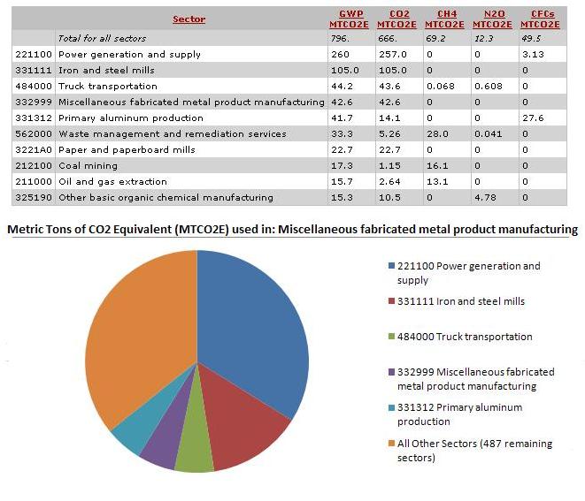
When an additional $1 million dollars is spent in the Miscellaneous fabricated metal product manufacturing sector, greenhouse gas emissions rise by approximately 796 metric tons of CO2 Equivalent (MTCO2E). The data shows that the majority of the gases are produced by power generation and supply, iron and steel mills, and transportation. The actual sector that produces the tap only produces 42.6 MTCO2E, which is small considering the amount released in other sectors.
- Toxic Releases
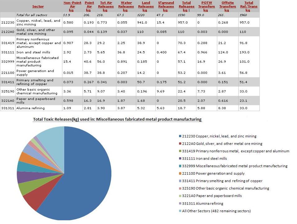
An additional $1 million dollars spent in the sector for keg taps results in a rise in total toxic releases of 1590kg. The primary contributors to these releases are mining of: copper, nickel, lead, and zinc gold, silver, and other metal ore mining. The Miscellaneous fabricated metal product manufacturing sector only amounts to a 57.1 kg increase in toxic releases.
Use
End of life
DFE Conclusions
Mechanical Analysis
- Include mechanical analysis to support quantitative understanding of the product's most critical mechanical aspects. Indluce a free body diagram, and be sure to define all symbols and explain all equations used.
Team Member Roles
- Identify team member roles during this phase and summarize your process. Submit individual peer evaluations to Prof.
