Lead-screw post hole digger
From DDL Wiki
(→Failure Modes and Effects Analysis) |
(→Failure Modes and Effects Analysis) |
||
| Line 200: | Line 200: | ||
|- valign="top" | |- valign="top" | ||
| rowspan="1" | All metal design | | rowspan="1" | All metal design | ||
| - | + | ||
| Transmission of electricity || | | Transmission of electricity || | ||
*User electrocuted, causing severe injury or death | *User electrocuted, causing severe injury or death | ||
Revision as of 23:03, 7 December 2008
Contents |
Overview
Background
The post hole digger is a common piece of landscaping equipment used to dig holes to erect posts and fences. Most common post hole diggers consists of two handles attached to metal shovel blades and joined via a hinge. Other, more complex designs involve an additional hinge that compounds the action of the handles, allowing the handles to be pulled apart at a smaller distance, supposedly easing the use of operation. To properly operate a post hole digger, the tool is thrust into the ground, the handles pulled apart to grasp the soil, and the entire apparatus lifted out of the soil, leaving a hole in the ground. The average post hole digger must be cheap, effective, reliable, and relatively lightweight.
Market Research
The post hole digger is a very essential, popular, and instrumental tool used in landscaping, therefore the team feels that improvements to the product will provide a great benefit to the general public. In further understanding the impact of creating an improved design, extensive market research has been conducted in determining the opportunity and cost-effectiveness of such improvements.
In summary, the team has taken a multi-pronged approach in its market research by
- Studying current existing post hole digging products
- Conducted actual usability studies on the most common brands
- Consulted with experts in the field
After identifying the areas for improvement, the team has developed a working prototype, the lead-screw post hole digger design. While the lead-screw design does address the market demands for an improved post hole digger, additional analysis had to be conducted to determine the feasibility of large scale production as well as the profitability of such an improved design. Thus the final, and possibly the most important step in our market analysis was conducted:
- Utilized general production volume and cost estimates along with Discounted Cash Flow analyses to understand the profitability of our proposed design.
It was found that all existing products in the market carry a two-handle design. We felt that the biggest demands related to improving this design is to reduce the weight as well as improve the quality of the overall digging experience. In other words, it was found that the current designs are all rather heavy (due to having two handles). In addition, operation of such two-handle designs also exhibit alot of physical strain on the user's arms, shoulders, and back as users repeatedly needed to open and close the handles while simultaneously lifting the digger while digging. We found through our usability studies as well as consulting with experts that a single handle design would greatly simplify the operation as well as reducing the weight of the design. These findings provide the inspiration for our single handle lead-screw post hole digger design .
Current Major Models and Designs
To begin, the team initially conducted a study in identifying the most common state-of-the-art existing post-hole digging products, while identifying pros and cons of each design. In addition, previous patents were also researched to identify and prevent any potential copyright infringements. A very thourough analysis has been conducted in Report 2. The following is an abridged version that highlight the top 2 most common post hole digger designs, which are also the subject of our usability studies to identify potential improvements.
Standard Post Hole Digger

The most common design for the post hole digger consists of a pair of simple wooden handles bolted onto two identical stamped steel shovel blades. These blades are connected via a single bolt with a sleeve that protects the bolt from soil and other foreign objects encountered during use. This design is identical to the simple post hole digger purchased and analyzed in Report 1, where the handles are pulled apart in a side-to-side motion while digging. This is a relatively sturdy design that utilizes the mechanical advantage of the pivot point to ampify the force applied by the user on the handles. For a more detailed analysis please consult Report 1.
Pros: Durable, high gripping force
Cons: Heavy, rounded shovel blades do not penetrate soil effectively, awkward to carry, no protection for knuckles
Complex Post Hole Digger

The complex post hole digger is a slight upgrade from the standard post hole digger, and is the other design in focus highlighted in our usability studies and in Report 1. This design utilizes an additional linkage that causes a compound action that reduces the distanced needed to pull apart the handles during operation. The design also has an additional add-on embedded between the handles to prevent the users from hitting their knuckles while digging. For a more detailed analysis on this design, please consult Report 1.
Pros: Durable, protection for knuckles, minimial pulling distance needed to grasp soil, sharp shovel blades to improve soil penetration ability
Cons: Heavy, loss of mechanical advantage from multiple pivot points, awkward to carry
Usability and Field Studies on Existing Products
After identifying the two most popular post hole diggers currently in the market. The team ventured out to a local Home Depot retailer and purchased the two post hole diggers and conducted a series of usability studies, first by ourselves and second with one male and one female test subject. For clarification, the two post hole diggers that were purchased are the simple and complex post hole diggers (illustrated in the section above).
First Study - Personal Field Testing
The first study involved our own group members physically dig holes with the post hole diggers on both hard and soft soil. A detailed analysis of this study can be seen in Report 1. In summary, after conducting this initial study of field tests with both post hole diggers, the most important areas for improvement we found were:
Sharper Shovel Blades - The complex post hole digger had a good shovel blade design in that the blades were pointed, allowing the post hole digger to penetrate deeper into hard soil. This is an advantage that should be adapted into future designs.
Weight Reduction - After repeatedly digging holes using both post hole diggers, the weight of the tool became a big issue as the user becomes fatigued. Possible weight reductions could involve shortening the handles or using less material in the shovel blades.
Second Study - Controlled Usability Study With Subjects
The second major usability test conducted was with two main subjects: one male and one female. The reason we did this additional test was to have a broader idea of how different users with different capabilities performed with the simple and complex post hole diggers, and to increase our exposure to a wider demographic of different end users. The extensive overview of the study is highlighted in Report 2.
From this usability test, it was verified with the subjects that that the sharper digging heads would be beneficial in the digging process, as it allows better penetration and a firmer grasp of the soil. In addition, one of the biggest findings was more aesthetic than functional, in that the test subjects preferred the complex post hole digger due to its flashier design with a painted finish. In addition, the subjects also noted that when initially presented with both post hole diggers, the subjects would purchase the complex post hole digger simply because it looks as if it was more effective, even if it does not necessarily perform better. This finding is important in creating a post hole digger that was not only functionally superior, but also had to look superior in order to be a profitable investment.
Consultation with Experts in the Field
Profitability Analysis of Improved Design - The Lead-screw Post Hole Digger
The Lead-Screw Post Hole Digger
List of Parts
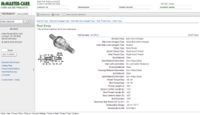
Table 1, located in the appendix of this report, is a comprehensive list of parts included in our design. Any applicable information regarding each component, such as part number, CAD images, fully dimensioned manufacturing drawings, vendor information for part or material orders, etc. can be found in this TABLE.
Assembly drawings
Also included in the appendix are several useful assembly drawings that verbally and pictorially explain how the design comes together. These include images of several subassemblies before and after being built, such as the aluminum shaft with the shaft handles and shaft pegs welded on, the central rod with guide bushings, shovel links, inline ball joint, and lead screw attached and ready for assembly, and the set up of the shovels and how they're attached to the shaft and shovel links. To view these exploded views of the CAD model for our design, with each component labeled by part number, click HERE.
Design For Manufacturing and Assembly
Design for manufacturing and assembly (DFMA) is a set of guidelines and processes that engineers and designers can implement to reduce the complexity and cost of manufacture of a product. Our new post hole digger design is analyzed below, considering Design for Manufacture (DFM) and Design for Assembly (DFA) guidelines. This analysis shows the strengths and weaknesses of the design in manufacturing and assembly processes, as well as a general guidelines on the types of processes used to make various components.
DFM
Our new post hole digger design exhibits both good and bad DFM characteristics. It is made from a total of 19 unique components, which is the same amount of unique parts in complex post hole digger examined in Report 1. This is a high number of parts is not a good DFM practice, but is necessary for our design, given the additional features it offers over traditional post hole diggers.
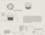
The part of this design that exhibits the worst DFM is the lead screw nut. Its complicated internal thread requires the use of a CNC lathe for cutting its helical pattern. Since there are 8 individual threads, the manufacturing time of this part is much longer than for a similar part with only one longer internal thread. The nut is also made of brass, which is a relatively expensive metal compared to steel or aluminum. This drives up the per part cost of the nut, which we estimate to be about $15 if the manufacturer makes it in-house. This nut is an integral part of our design, so it cannot be elimnated, regardless of its DFM qualities. We justify for two main reasons: the high number of threads gives a large linear travel per turn, which is important in reducing the number of turns needed to close the shovels, an imortant aspect of our design. Also, brass, with its low friction and high wear resistance, is the ideal material to interface with the steel lead screw. It is a very tough material that will last for the life of the tool, which is very important since the nut is so critical to the mechanism of our design.
Despite the high part count, our design does have several good DFM attributes. Most of the post hole digger is made from aluminum, and all of these aluminum parts are made from some sort of extruded shape. The initial capital for purchasing an extrusion machine would be high, but the costs to maintain the machine and tooling would be low. With an in-house extrusion setup, the manufacturer would only have to purchase aluminum billets for extrusion, rather than paying another supplier more money for the variety of extrusions used in this design. The in-house extrusion machine(s) also gives the manufacturer tight control over the amount of extrusion produced for each manufacturing run, helping to eliminate waste. Additionally, the extrusion machine make a variety of shapes by simply changing dies, so is could be used to make components for other products that the manufacturer makes.
The extruded aluminum parts have addtional features that are added by processes by machining, turning and bending. All of these processes can be automated, which will help speed production. The parts requiring machining and drilling can be put into a jig in a CNC machine (with multiple parts in a jig) to perform the operations very quickly and efficiently. Turning can be performed in an CNC lathe with a stock feeder, which allows for continous production parts of at high rates.
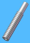
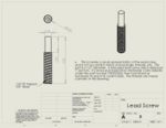
The shovels of our post hole digger are made from stamped steel, just like in other digger designs. Stamping is a proven process in the industry and capable of both accuracy and high production rates. The steel lead screw is also easy to produce; it can be made quickly on a CNC lathe with stock feeder. The lead screw does have 8 individual threads like the lead screw nut, but, unlike the nut, these threads are external, which are much easier to cut in a turning operation.
Good DFM practice dictates that secondary finishing operations be minimized, and we have tried to do so in our design. There are two operations that need to be performed. The steel in the shovels and crank is susceptible to rusting, and it must be protected against rust since this tool is used in a typically moist environment. Simply painting the shovels and crank will help prevent this corrosion and prolong their life. The other finishing operation that must be performed is anodizing of the aluminum shaft assembly. Unfinished extruded and machined aluminum is susceptible to oxidation. Oxidation would be accelerated in the abusive environment that a post hole digger is used in, so anodizing, which protects aluminum from oxidation, is necessary.
DFA
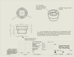
The DFA characteristics of our new post hole digger design are relatively good. This design manages to minimze the number of fasters used. There are a total of four bolts in the assembly, and each is relatively easy to orient and place, along with their individual lock nuts. Fastner count is also reduced by the use of other joining processes. The lead screw nut bushing uses a heat shrink fit to be secured in the shaft, which requires no additional fasteners and creates a joint that is much stronger than a joint being secured by set screws. The lead screw nut also has integral external threads that tighten into the lead screw nut bushing, so no extra fasteners are needed.
Our design is also broken into two sub assemblies, which aids in production since these sub assemblies can be put together indepently before the final assembly steps. Having sub assemlbies also allows for unrestricted access to fastners and parts which could potentially be obstructed if the assembly was performed in one single process.
There are several welding operations that must be peformed on our design which increase the time and cost of production. The handles and foot pegs, which are necessary components to the design, must be welded to the shaft. Since these components are made from aluminum, they must be TIG welded. Aluminum MIG processes exist, but they are suited for large scale welds, not the smaller, more delicate welds that we require. While TIG welding creates clean, controlled welds, it is a time consuming process. Also, the foot pegs and handles must be placed in a jig with the shaft so that all the parts are held in proper alignment while they are welded. The welds must also be solid beads along the interface between the shaft and the parts, so the shaft may require reorientation to complete the welds after parts have been tacked in place. Obviously, this will be the most time comsuming part of the assembly operation. In order to make this process faster, we plan to implement robotic TIG welders, which will also be capable of creating high quality welds consistently.
Despite the challenges presented by welding, our design still has some additional quality DFA characteristics. Much of the assembly process is mistake proof. The parts that require specific orientation when being assembled (the lead screw, for example) have features that allow the part to be placed or joined in one way (the lead screw only has a threaded hole in one end for mating with the inline ball joint.) Also, parts that do not require highly specific orientation, like the guide bushing of shovel links, have symmetry about one or more axes to minimize the manipulation required to place the part.
DFMA Conclusions
The lead screw post hole digger design exhibits fair DFMA characteristics. The large number of individual parts does not benefit DFM of DFA. The brass lead screw nut, an essential component of the design, is difficult to manufacture and made of a costly material, which makes it the most expensive part of the design. The use of extruded components and in-house extruding machines create an efficient manufacturing process, minimizing costs and waste. The processing of these extruded components, made from aluminum, can be done quickly using automated CNC milling and turning processes. Like other post hole diggers, this design utilizes stamped steel digging heads, which are easily manufactured. Secondary finishing operations are minimized, with only simple painting and anodizing needing performed.
The lead screw post hole digger has several compoments requiring TIG welding, which is a time consuming process. Robotic welders would be implemented to expedite this process while still maintaining high quality weld joints. This design minimizes fastners and utilizes sub assemblies to simplify the assembly process. Also, many parts have characteristics that make the assembly process clear and unambiguous.
Design for Environment
Failure Modes and Effects Analysis
| Item & Function | Failure Mode | Effects of Failure | S | Cause of Failure | O | Design Controls | D | RPN | Recommended Actions | Responsibility & Deadline | S* | O* | D* | RPN* |
|---|---|---|---|---|---|---|---|---|---|---|---|---|---|---|
Digging Head
| Bends |
| 7 | Improper use, impact into rock, applying excessive force | 6 | Strength test metal to ensure quality and durability | 2 | 84 |
| Manufacturer, Designer | 7 | 4 | 2 | 56 |
| Rusts |
| 4 | Storage in a moist environment | 4 | Ensure adequate coating of paint applied, test durability | 2 | 32 |
| Manufacturer, Designer | 4 | 2 | 3 | 24 | |
Central Rod Bolt
| Shears or bends |
| 8 | Corrosion of bolt, high impact force transmitted from digging heads | 3 | Ensure no defects in bolt material and coating | 7 | 168 |
| Designer, Manufacturer | 8 | 2 | 5 | 80 |
Foot Peg
| Detaches from shaft |
| 4 | Failure of weld, application of excessive force | 4 | Inspect Welds | 2 | 32 |
| Designer, Manufacturer | 4 | 3 | 2 | 24 |
Lead Screw Nut Bushing
| Detaches from shaft |
| 7 | Extreme force application to handle, lead screw nut pulls on bushing, pulls out nut | 6 | Ensure proper heat shrink | 2 | 84 |
| Designer | 7 | 4 | 2 | 56 |
Inline ball joint
| Seizing, wear |
| 5 | Wear and tear | 5 | Ensure lubrication of ball joint | 3 | 75 |
| Designer, Manufacturer | 5 | 3 | 3 | 45 |
Shaft handle
| Detaches from shaft |
| 4 | Failure of weld, application of excessive force | 4 | Inspect Welds | 2 | 32 |
| Designer | 4 | 3 | 2 | 24 |
Crank
| Detaches from lead screw, bending |
| 6 | Failure of weld joint between lead screw and crank, application of excessive force | 5 | Inspect welds, strength test steel crank | 2 | 60 |
| Designer, Manufacturer | 6 | 4 | 2 | 48 |
Central Rod
| Bending |
| 4 | Application of excessive force | 5 | Perform bending analysis on design, ensure proper placement of guide bushings | 4 | 80 |
| Designer | 4 | 4 | 4 | 64 |
Pivot connection bolt
| Rusts, breaks |
| 8 | Moisture causing rust and corrosion of bolt | 2 | Use rust-resistant bolt | 6 | 96 |
| Designer | 8 | 2 | 4 | 64 |
| All metal design | Transmission of electricity |
| 10 | Striking underground power line | 3 | User warned of electrocution hazard | 6 | 180 |
| Designer | 10 | 1 | 5 | 50 |
FMEA Conclusions
Quality Function Deployment
For additional information on our QFD analysis, please see Post Hole Digger: Additional Information.
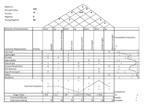
In our analysis of post hole diggers, we used Quality function deployment, or QFD, as a means of ensuring that the needs or 'voice' of the customer were considered when designing our product and also for comparing ourselves to current competitors and product specifications. Essentially, the QFD is a matrix that relates the needs of the customer to the product specifications and helps to ensure the creation of a high quality product. The most common type of QFD and the one we have used in our analysis is a product planning matrix or a 'house of quality'.
Conclusions
The Quality Function Deployment for our product is shown on the right in Figure 1; as noted above, we chose to use a Product Planning Matrix or 'House of Quality'. Our QFD helped to reinforce initial thoughts on customer desires, place targets for a number of quantitative goals, and determine how we compared to the competition. Most of the results of this were somewhat expected, namely that consumers are most interested in ease of use(mechanical advantage), light weight, and high shovel volume, all factors that contribute to the speed at which digging can occur. As a result, we set goals for ourselves in a number of these categories that we sought to achieve when designing and building our post hole digger. Our final design meets or exceeds our initial goals in nearly all areas, and consistently places us on pace with or ahead of the competition; this leads to our belief that our product is of high quality and will be successful in the marketplace. However, it should be noted that not all results from our QFD were taken verbatim. For example, although tool and handle length were considerations of ours in designing our product, our target values were never taken as exact goals to be reached regardless of the cost; instead we attempted to create the best overall product that emphasized the main values discussed above.
Mechanical Analysis
Details from our Mechanical Analysis can be found at Post Hole Digger: Additional Information
Our mechanical analysis of our product was carried out in two main phases. The goal of our first analysis was to optimize the design of our post hole digger by determining an appropriate lead screw design to purchase and then use in the development of our product. In order to do this, we did a simple mechanical analysis by hand that developed several formulas for use in Microsoft Excel Solver. The result of this analysis was a set of parameters describing the ideal lead screw for our design, and the selection of a screw that most closely matched these parameters for use in our prototypes (and eventually our final product). Our second analysis focused mainly on the durability associated with our product and whether or not the design would be sufficiently strong to withstand the rigors of post hole digger use. This analysis focused on the strength of the threads of the lead screw and the shear stresses on a number of the bolts used in our design. We determined that all of these components had high factors of safety and would thus be suitable for their intended use.
Prototypes
Prototype I
Prototype II
Prototype III
Appendix
Table 1: List of parts
Exploded views for assembly
Aluminum shaft assembly:
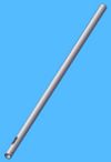
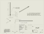
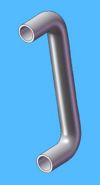
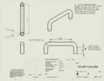
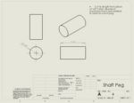
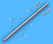
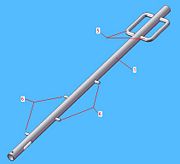
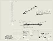
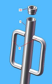
The following images (E1 through E3) depict the assembly of the entire aluminum shaft and its components. Figure E1 shows each of the components prior to assembly, including the shaft, two shaft handles, and four shaft pegs. To reach the final state shown in Figure E2, the two handles and four pegs are welded to the shaft in the appropriate locations as specified by the manufacturing drawing shown in Figure E3.
Lead screw nut bushing assembly:
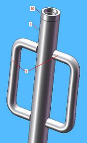
After having completed the assembly of the aluminum shaft, the lead screw nut bushing must be placed in the open end of the shaft (end nearest the handles). Figures E4 and E5 show this process both before and after completion. To secure the bushing in place, a heat shrink fit will be used by heating the end of the shaft, placing the bushing accordingly, then allowing the assembly to cool. This thermal connection should be very strong and last for ages if done correctly.
Central rod assembly:
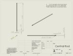
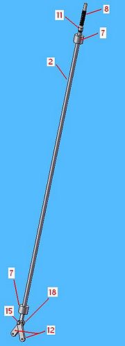
The following three images (E6 through E8) show the assembly process of the central rod before it is fed upwards through the completed aluminum shaft assembly.
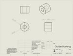
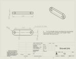
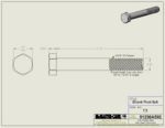
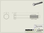
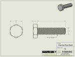
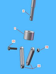
In Figure E6, the bottom end of the central rod assembly is shown before completion, including the tip of the central rod, a guide bushing, the two shovel links, and the central rod bolt along with the appropriate 1/4"-20 nylon lock nut. To assemble, the guide bushing is first pressed onto the central rod such that the bottom face of the bushing is flush with the rod where the machined flats begin. After this, the two shovel links are attached by placing one on each side of the machined flats, aligning their holes with the hole in the central rod, then placing the central rod bolt through the completed hole and threading on the 1/4" nylon lock nut.
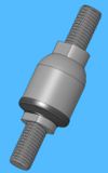
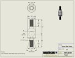
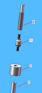
Figure E7 depicts the components comprising the top end of the central rod assembly, including the top tip of the central rod, the last guide bushing, the inline ball joint, and finally, the lead screw. To begin the assembly, the guide bushing is pressed onto the top end of the central rod such that the top face of the bushing is located approximately 1" from the top face of rod (near the threaded hole). Next, the male shank on the ball-end of the inline ball joint is threaded into the tapped hole located on the end of the central rod. Lastly, the lead screw is threaded onto the male shank of the socket-end of the inline ball joint, much like a nut would be tightened onto a bolt. The threaded connections of the ball joint will then be tightened using the appropriate sized wrench on the flats of the ball joint shanks.
After having completed all of this the central rod assembly is now complete and should look like image shown in Figure E8.
Placing central rod assembly into the completed aluminum shaft assembly:
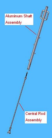
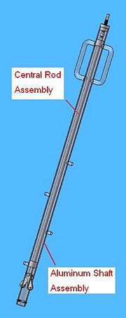
Following the completion of the central rod assembly, we are now ready to place it in the aluminum shaft and feed it up through the top. To do this, the lead-screw-end of the central rod assembly is fed up through the bottom of the completed aluminum shaft assembly (end near foot pegs and machined slots) until approximately half of the lead screw can be seen protruding from the top end of the shaft near the lead screw nut bushing. Figure E9 shows the two assemblies just before putting them together. After feeding the central rod assembly up through, the two guide bushings will be completely contained within the shaft, the lead screw will be exposed at the top, and the two shovel links will be ready to be pulled through the machined slots near the bottom in order to attach the shovels. Figure E10 shows the new assembly after completing this step, and the tool is now read to have the lead screw nut put into place. The aluminum shaft assembly has been made transparent to enable you to see the central rod assembly within.
Lead screw nut assembly:
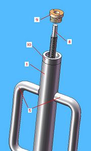
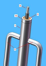
At its current state, the entire assembly is ready to include the lead screw nut. This is done by firmly holding the lead screw in place and threading the nut on with the flanged end up. Figure E11, below, shows the components just prior to being assembled. After this, the nut and lead screw are pushed downward so that the external threads of the lead screw nut can be threaded into the tapped hole of the secured lead screw nut bushing. This can then be tightened using a spanner wrench and the two pin holes located in the top flange of the lead screw nut. The completed portion of the tool assembly is shown in Figure E12 below.
Shovel assembly:
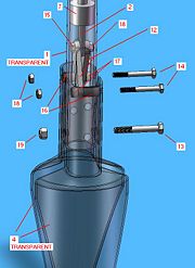
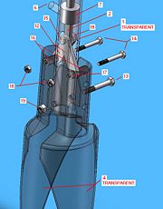
With the central rod assembly, and other main components now in place, the shovels must be attached to the shaft and shovel links. Figures E13 and E14 show transparent images of the various components needed to do this just before being assembled. In Figure E13, a side view is taken so that all of the components can be seen, while Figure E14 is an isometric view to give a visual of where the parts are with respect to one another before assembly.
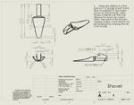
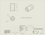
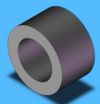
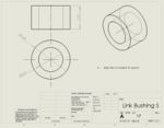
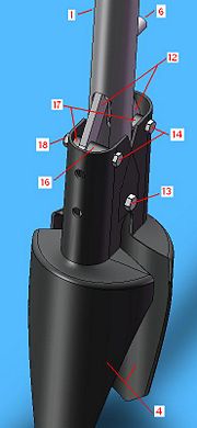
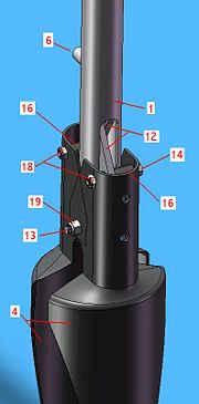
First, the holes near the middle of the shovels, which houses the main pivot bolt, must be aligned by slightly squeezing one shovel and placing it within the confines of the other. The shovels must then be slipped over the bottom end of the shaft, aligning them with the hole for the main pivot bolt. Once everything is aligned the bolt can be slipped all the way through, and the 5/16"-18 Nylon lock nut can be threaded on to secure the pivoting connection. Next, the shovel links must be secured to the shovels. Before doing so, the correct link bushings must be placed between the respective link and shovel on either side. These bushings help keep the shovel links from flopping around and maintain the correct spacing between the shovels and links. For each link-to-shovel connection, Link bushing L will be placed in the larger gap between the shovel and link, while Link bushing S will occupy the smaller gap on the other side of the link. Once the holes and bushings are aligned, the shovel link bolts can be pushed through and attached using a 1/4"-20 Nylon lock nut. This completes the shovel assembly, as depicted in the two opaque isometric views of the tool in Figures E15 and E16.
Crank assembly:
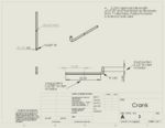
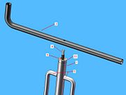
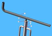
At this point the tool is all most completely assembled, only lacking the steel crank used to turn the lead screw and close the shovels. The long leg of the L-shaped crank should be perpendicular to the shaft such that the hole in the middle is aligned with the top end of the lead screw, and the short leg of the crank is facing upward, parallel with the shaft. Figure E17 shows the crank in the correct location just before being attached to the lead screw. The crank is then lowered onto the machined end of the lead screw until it's bottom edge butts up against the top face of the lead screw's threads. Also, the top tip of the lead screw should now be flush with the hole in the crank. The crank should now be secured by fully welding it to the lead screw near both of its holes which interface with the screw. The completed crank assembly is depicted in Figure E18, below.
Complete tool:
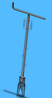
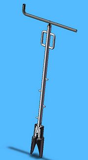
The following two Figures, E19 and E20, show the completed design with all components in place. The first image, Figure E19, uses a transparent shaft and shovels to allow viewing of the inner workings of the tool. Figure E20, then, is an opaque image of the tool in its complete state, much like what the user would see when using the tool.
