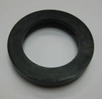
Low-foam keg tap
From DDL Wiki
(→Design Documentation) |
(→Design Analysis) |
||
| Line 636: | Line 636: | ||
| align="center"|21 | | align="center"|21 | ||
| - | | align="center"| | + | | align="center"|Main Block |
Sub-assembly | Sub-assembly | ||
| align="center"|Releases Beer from Hose | | align="center"|Releases Beer from Hose | ||
| Line 651: | Line 651: | ||
|- | |- | ||
| - | |||
| - | |||
| - | |||
| - | |||
| - | |||
| - | |||
| - | |||
| - | |||
| - | |||
| - | |||
| - | |||
| - | |||
| - | |||
| - | |||
| - | |||
| - | |||
| - | |||
| - | |||
| - | |||
| - | |||
| - | |||
| - | |||
| - | |||
| - | |||
| - | |||
| - | |||
| - | |||
| - | |||
| - | |||
| - | |||
| - | |||
| - | |||
| - | |||
| - | |||
| - | |||
| - | |||
| - | |||
| - | |||
| - | |||
| - | |||
| - | |||
| - | |||
| - | |||
| - | |||
| - | |||
| - | |||
| - | |||
| - | |||
| - | |||
| - | |||
| - | |||
| - | |||
| - | |||
| - | |||
| - | |||
| - | |||
| - | |||
| - | |||
| - | |||
| - | |||
| - | |||
| - | |||
| - | |||
| - | |||
| - | |||
| - | |||
| - | |||
| - | |||
| - | |||
| - | |||
| - | |||
| - | |||
| - | |||
| - | |||
| - | |||
| - | |||
| - | |||
| - | |||
| - | |||
|} | |} | ||
Revision as of 14:15, 5 December 2009
Contents |
Executive Summary
Provide a brief executive summary summarizing your findings and conclusions. In particular, summarize
- Findings from market research justifying need for the new product: Survey distributed; found that users desire a lower foam output, easier pumping mechanism, and more intuitive tap design
- The product's main features, advantages over competitors, and target market: center cylinder redesigned to eliminate 90 degree bend in liquid output (straight tube means less foam), final product will include pressure gauge to prevent overpumping; competing products create more foam; target market is beer distributors and college students
- The most important findings from your product analyses that justify design choices and support your case for the new product.
Market Analysis
Make the case that there exists a market need for your product using market research findings, illustrative pictures, benchmarking against competitors, and identifying your target market. Estimate a ballpark expected price and production volume for the product and compare against expected cost. Determine if the product has high likelihood to be profitable or unprofitable or if more information is needed to determine. Is there enough potential to justify investment in further market research and testing?
Design Documentation
Include assembly drawings with all components labeled as well as a bill of materials defining each component with quantity, material, etc. Include a fully dimensioned CAD drawing for each custom component and a company and part number for each purchased component.
Whether or not the base is cast or bought depends on the production volume. As of now, the assumption is that the number of taps produced will not make it worth it to make the part. The individual component can be purchased at ____ for $xx.
House of Quality
Provide a complete house of quality table to summarize your design choices, targets, relationships, and benchmarking against the competition. Highlight major findings and conclusions.
Design Analysis
Report on conclusions and recommendations from your DFMA, FMEA, and DFE findings for your product, and benchmark against the competition. Highlight major findings in the report and provide data in the appendix.
- DFE
Our DFE conclusions from the tap design in use currently, showed that our group should work to reduce the amount of foam created. The foam was the largest component of greenhouse gas emissions associated with our product. Therefore reducing the foam created would be a great way to reduce the impact our product has on the environment. See Keg tap Section 8.
Due to the number and types of changes we have made to the original tap to create our foam-reducing tap, the DFE for our product would be identical to the original tap, with one major change: the amount of foam created by our product is less. The reduced foam creation in our tap means our product will have a reduced impact on the environment.
- FMEA
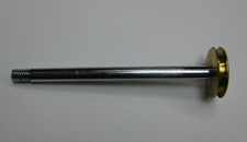
The following FMEA is very identical to the FMEA done on the current tap design due to multiple parts being the same. The key differences that should be highlighted are the changes in the handle, the changes in the center cylinder. and the addition of the main block.
The new handle may cause a few new problems, such as improper taping and binding. The old tap design inadvertently forced the user to tap the keg the proper way by grabbing the plastic handle near the base and twisting. Now that our handle for pumping is larger the user may try taping the keg with that part, which may tighten/loosen some of the threaded parts instead of taping the keg. The other problem of binding was cause for concern before the prototype was actually completed. It was thought that having the double barrel may cause the plungers to bind, no allowing the user to pump the tap easily. After completing the prototype and testing multiple times this does not seem to be a problem.
The FMEA done on the original tap led our group to make changes on the center cylinder. It was this part that received the highest RPN (49) the first time around. It received that number due to the flow path it made the beer follow. The testing and mechanical analysis we have done shows that more foam is created when the beer has to go around a 90 degree bend. With that in mind our group decided to redesign this piece so that there were no bends in it, allowing for the least amount of foam to be created in it, ultimately lowering its RPN.
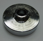
Lastly the main block is a new part added to our re-design. Just as the new handle is a place to tap the keg improperly, the main block could give the user a place to make the same mistake. If tapped by twisting the main block, threaded parts may be tightened or loosened instead of the keg being properly tapped. One way to combat this problem would be to put warning signs on the tap, or to make the handle by the base bigger so the user will want to use that to tap the keg.
| Part # | Item | Function | Failure Mode | Effects of Failure | S | Cause of Failure | O | Design Controls | D | RPN | Recommended Actions |
|---|---|---|---|---|---|---|---|---|---|---|---|
| 1 | Handle | Grip for Pumping | Could bind while trying to pump | Rough pumping | 7 | Poor Design | 1 | Design it to function smoothly | 1 | 7 | Had no trouble with this in prototype |
| 2 | Plungers | Force Air into Keg | Could be snapped off while locked into keg | Unusable | 7 | Unaware Users | 1 | Increase diameter | 1 | 7 | Even more less likely now |
| 2.1 | Plunger Disc | Air Tight | This part is very robust. Cannot foresee any failure modes. | --- | - | --- | - | --- | - | - | --- |
| 3 | Plunger O-Ring | Seal | O-ring becomes hardened | Loss of air tight seal for pressurizing keg | 3 | Repeated use and time | 2 | Oil the o-ring | 5 | 30 | Sell spare parts |
| 4 | Cylindrical Plunger Casing | Supply Keg with Pressure | Dent in the casing, burs, scratches, rust on the inside of the casing | Plunger cannot be moved inside the case, o-ring gets torn up | 7 | Misuse, Dropping the tap | 1 | All these pieces are robust enough | 1 | 7 | None |
| 5 | Cylindrical Casing O-Ring | Seal | O-ring becomes hardened | Loss of air tight seal for pressurizing keg | 3 | Repeated use and time | 2 | Oil the o-ring | 5 | 30 | Sell spare parts |
| 6 | Cylindrical Top | Encloses Plunger in Casing | Top comes unscrewed | Cannot pressurize keg | 1 | Human tampering | 4 | Check that it is screwed on tightly | 2 | 8 | None, gluing these threads makes disassembly harder |
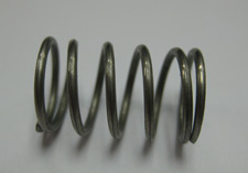
| 7 | Plunger Spring | Prevents Plunger from Getting Stuck | Breaks | Plunger, though unlikely, may get stuck at top of casing | 7 | Misuse or fatigue | 1 | Make sure spring can handle forces | 1 | 7 | Sell spare parts |
| 8 | Center Cylinder | Separates Air Input from Beer Output | 1)Leaks beer at the connection point with hose
2)Creates turbulence in beer flow | 1)Loss of beer
2)Foamy beer | 7 | 1)Sealant on threads is old
2)Manufacturing | 7 | 1)Check that their are no leaks
2)Their Design | 1 | 49 | 1)None
2)Look into some other way to transition into tubing |
| 9 | Center Cylinder O-Ring | Seal | O-ring becomes hardened | Loss of air tight seal for pressurizing keg | 3 | Repeated use and time | 2 | Oil the o-ring | 5 | 30 | Sell spare parts |
| 10 | Lever | Attaches Tap and Keg allowing the flow of beer | This part is very robust. Cannot foresee any failure modes. | --- | - | --- | - | --- | - | - | --- |
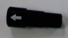
| 11 | Lever Casing | Grip for user | Breaks | Unable to attach tap to keg | 7 | Ridiculous Misuse | 2 | Make sure the part is strong enough | 1 | 14 | None |
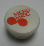
| 12 | White Cap | Aesthetics | Could break or get lost | None | 1 | Misuse or overuse | 2 | Check this fit | 1 | 2 | None |
| 13 | Lever Spring | Helps lock tap in two certain positions | Impact fatigue | Unable to lock tap into open position on keg | 7 | User misuse | 1 | Make sure spring can handle forces | 2 | 14 | Brainstorm new ways to lock tap |
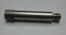
| 14 | Center Rod | Helps hold handle together | This part is very robust. Cannot foresee any failure modes. | --- | - | --- | - | --- | - | - | --- |
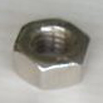
| 15 | Nut | Helps hold handle together | Could come unscrewed | Unable to use tap | 7 | Repeated use | 1 | Make sure it is screwed on the whole way | 1 | 7 | None |
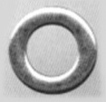
| 16 | Washer | Helps hold handle together | Cannot foresee any failure modes | --- | - | --- | - | --- | - | - | --- |
| 17 | Lever Pin | Attaches the lever to the base and acts as a pivot point for the lever | No foreseen failure modes. | --- | - | --- | - | --- | - | - | --- |
| 18 | Base | Attaches to Keg | Threads become crooked | Unable to connect tap to keg | 7 | Terrible misuse | 1 | Threads are very robust | 2 | 14 | Sell spare parts |
| 19 | Base O-Ring | Seal | O-ring becomes hardened | Loss of air tight seal for pressurizing keg | 3 | Repeated use and time | 2 | Oil the o-ring | 5 | 30 | Sell spare parts |
| 20 | Hose | Transfers Beer from Tap to Cup | 1)Hole
2)Kink | 1)Beer is lost
2)Beer cannot reach its destination | 7 | 1)Not taking care of tap
2)Jokes | 1 | Make sure the tubing is the right kind | 2 | 14 | None |
| 21 | Main Block
Sub-assembly | Releases Beer from Hose | Failures will follow from individual parts | --- | - | --- | - | --- | - | - | --- |
- DFMA
Mechanical Analysis
Clearly state the purpose of the analysis, methods and assumptions. Define all symbols, and provide a free body diagram, if applicable. Summarize conclusions and implications for you design, and explain how the analysis serves to justify your design choices.
Prototype Documentation
Document your final prototype, explain what it demonstrates about your design, and clearly identify differences between your prototype and final design intended for mass production. Summarize findings from user testing and user feedback.
Design Process
Include a short section documenting your team design process for scheduling, coordinating, and completing tasks. Identify individual team member roles, responsibilities, and contributions. Assess the state of the product. Is the design ready for production? If not, what are the next steps (eg. more testing, quantitative market research)?
Appendix
Include Design analysis data here.
