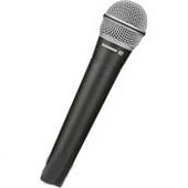
Microphone
From DDL Wiki
(Difference between revisions)
(→Design for Environment) |
(→Parts List) |
||
| Line 29: | Line 29: | ||
|- | |- | ||
!1 | !1 | ||
| - | | ||Ring ||2 ||attaches to mic end of boom shaft ||Steel ||Machining | + | |[[Image:ring.jpg]] ||Ring (2x) ||2 ||attaches to mic end of boom shaft ||Steel ||Machining |
|- | |- | ||
!2 | !2 | ||
| - | | ||Boom shaft ||493 || || | + | | ||Boom shaft ||493 ||Steel Pipe(mass includes counterweight) ||Steel||Extrusion |
|- | |- | ||
!3 | !3 | ||
| - | | || | + | | ||Counterweight || ||Solid||Steel ||Casting |
|- | |- | ||
!4 | !4 | ||
| - | | ||Mic holder ||10 ||'' ||Casting and machining || | + | | ||Mic holder ||10 ||''|| ||Casting and machining || |
|- | |- | ||
!5 | !5 | ||
| Line 53: | Line 53: | ||
|- | |- | ||
!9 | !9 | ||
| - | | ||Rubber pad ( | + | | ||Rubber pad (2x) ||8 ||goes inside #8 to hold #11 in place||Rubber||Molding |
|- | |- | ||
!10 | !10 | ||
| Line 65: | Line 65: | ||
|- | |- | ||
!13 | !13 | ||
| - | | || | + | | ||Handle || ||Has a threaded hole in which the end of #10 is inserted||Steel||Casting and machining |
|- | |- | ||
!14 | !14 | ||
| - | | || | + | | ||Thumbscrew ||3 ||Holds boom in place. Goeas through hole in #11. Has plastic nub so as not to scratch the boom ||Two kinds of plastic (head and nub) and steel (screw) ||Molding (plastic) and machining (steel) |
|- | |- | ||
!15 | !15 | ||
| - | |||
| - | |||
| - | |||
| ||Wire clip ||2 ||Attaches to mic stand, used to hold wire in place ||Plastic ||Molding | | ||Wire clip ||2 ||Attaches to mic stand, used to hold wire in place ||Plastic ||Molding | ||
|} | |} | ||
| Line 137: | Line 134: | ||
| cell 2,1 || Metal screen ||49 ||Made of a wire mesh attached to metal rings ||Steel ||Extrusion, weaving, ??(Don't know how rings are attached) | | cell 2,1 || Metal screen ||49 ||Made of a wire mesh attached to metal rings ||Steel ||Extrusion, weaving, ??(Don't know how rings are attached) | ||
|} | |} | ||
| - | |||
| - | |||
| - | |||
| - | |||
| - | |||
== Design for Manufacturing and Assembly (DFMA) == | == Design for Manufacturing and Assembly (DFMA) == | ||
Revision as of 17:15, 20 September 2009
Contents |
Executive Summary
-Dan
Stakeholders
-Luo
User Study
-Nakul
Assembly
-Justin
Function of the System
Mechanical Analysis
-Nakul
Parts List
-Dan
| Part Number | Photo | Part name | Masss(g) | Notes | Material | Manufacturing Method |
|---|---|---|---|---|---|---|
| M1 | cell 1,1 | Switch slider | <1 | cell 1,2 | Plastic | Molding |
| M2 | cell 2,1 | Sticker A | <1 | Goes on M1 | Plastic | Stamped out of a thin sheet |
| M3 | cell 2,1 | Screw A (2X) | <1 | Holds switch electronics to the microphone body | Steel | Machining |
| M4 | cell 2,1 | Screw B | <1 | Atttaches gground pin to the back of the microphone body | Machining | |
| M5 | cell 2,1 | Body | 187 | Large, machined | Metal | Casting and machining, sandblasted finish |
| M6 | cell 2,1 | Rubber disc | 2 | Holds three pins in place | Rubber | Molding |
| M7 | cell 2,1 | Pin | 1 | Transmits signal from the microphone to the wire | Metal | ????? |
| M8 | cell 2,1 | Switch electronics | 3 | Use physical user input from switch to affect electrical circuit | Plastic housing, metal wire | Molding (housing), extrusion (wire) |
| M9 | cell 2,1 | Foam cover | <1 | Covers the magnet and diaphragm | Polymer foam | ???? |
| M10 | cell 2,1 | Plastic cover | 2 | Protects diaphragm and magnet | Plastic | Molding |
| M11 | cell 2,1 | Chip | <1 | Takes signal from coil (M13) and transmits it to the the pins. Is glued to a slot on M16 | Silicon chip, copper conductors | Chemical etching |
| M12 | cell 2,1 | Diaphragm | <1 | Made from a thin piece of plastic with a spiral stamped into it to give it better elastic properties | Plastic | Stamping |
| M13 | cell 2,1 | Coil | <1 | Thin insulated copper wire | Copper | Extrusion |
| M14 | cell 2,1 | Magnet | 5 | Attached to diaphragm | Magnetic metal | Casting |
| M15 | cell 2,1 | Sticker B | <1 | Covers cavity in the housing, below where the magnet sits | Plastic | Stamping |
| M16 | cell 2,1 | Housing | 10 | Holds parts M11-M15, the parts that actually convert sound into an electrical signal | Plastic | Molding |
| M17 | cell 2,1 | Wind screen | <1 | Made of a hollow foam ball. Inserted into the metal screen. Used to soften sounds of users' voices | Polymer foam | ???? |
| M18 | cell 2,1 | Metal screen | 49 | Made of a wire mesh attached to metal rings | Steel | Extrusion, weaving, ??(Don't know how rings are attached) |
Design for Manufacturing and Assembly (DFMA)
-Dan and Justin
-Improve ease of disassembly for repair
Failure Modes and Effects Analysis
Considering ways in which a product could potentially fail is a crucial part of the design process. All products must be designed such that they are both safe and reliable for use and any potential dangers must be addressed in the design phase.
| Assembly/Parts | Failure Mode | Consequence of Failure | S | Causes of Failure | O | Prevention | D | RPN | Recommendations | Responsibility |
|---|---|---|---|---|---|---|---|---|---|---|
| On/Off Switch | Soldering Becomes Loose | Microphone will not turn on | 7 | Bad soldering | 2 | N/A | 2 | 28 | Check soldering before assembly | Controls engineer |
| Diaphragm | Torn Diaphragm | Inoperable | 7 | Misuse or Outside particles gets inside microphone | 1 | Foam Cover | 2 | 14 | None | N/A |
| Extending Stand | Grip fails | Stand does not stay extended | 5 | Wear from lots of use | 1 | Exploded end | 1 | 5 | Add rubber stoppers or grips | Design Engineer |
| Microphone Clip | Loose Joint | Unable to orient to desired location | 4 | Loose Screws, wear from use | 6 | N/A | 1 | 24 | Tighten Screws constantly, add friction to joint | Controls Engineer |


