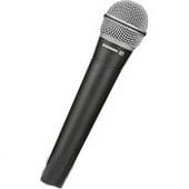
Microphone
From DDL Wiki
Contents |
Executive Summary
-Dan
this page needs a fricking backlink!
Engineering_Design_II_-_Conceptualization_and_Realization_Course
Stakeholders
-Luo
yes i am a stakeholder
User Study
-Nakul
Assembly
-Justin
Function of the System
Mechanical Analysis
-Nakul
Parts List
-Dan & Justin
| Part Number | Photo | Part name | Masss(g) | Notes | Material | Manufacturing Method |
|---|---|---|---|---|---|---|
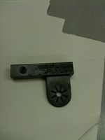
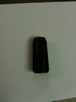
| M1 | cell 1,1 | Switch slider | <1 | cell 1,2 | Plastic | Molding |
| M2 | cell 2,1 | Sticker A | <1 | Goes on M1 | Plastic | Stamped out of a thin sheet |
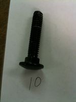
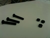
| M3 | cell 2,1 | Screw A (2X) | <1 | Holds switch electronics to the microphone body | Steel | Machining |
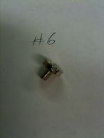
| M4 | cell 2,1 | Screw B | <1 | Atttaches gground pin to the back of the microphone body | Steel | Machining |
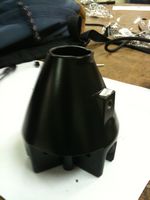
| M5 | cell 2,1 | Body | 187 | Large, machined | Metal | Casting and machining, sandblasted finish |
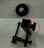
| M6 | cell 2,1 | Rubber disc | 2 | Holds three pins in place | Rubber | Molding |
| M7 | cell 2,1 | Pin | 1 | Transmits signal from the microphone to the wire | Metal | ????? |
| M8 | cell 2,1 | Switch electronics | 3 | Use physical user input from switch to affect electrical circuit | Plastic housing, metal wire | Molding (housing), extrusion (wire) |
| M9 | cell 2,1 | Foam cover | <1 | Covers the magnet and diaphragm | Polymer foam | ???? |
| M10 | cell 2,1 | Plastic cover | 2 | Protects diaphragm and magnet | Plastic | Molding |
| M11 | cell 2,1 | Chip | <1 | Takes signal from coil (M13) and transmits it to the the pins. Is glued to a slot on M16 | Silicon chip, copper conductors | Chemical etching |
| M12 | cell 2,1 | Diaphragm | <1 | Made from a thin piece of plastic with a spiral stamped into it to give it better elastic properties | Plastic | Stamping |
| M13 | cell 2,1 | Coil | <1 | Thin insulated copper wire | Copper | Extrusion |
| M14 | cell 2,1 | Magnet | 5 | Attached to diaphragm | Magnetic metal | Casting |
| M15 | cell 2,1 | Sticker B | <1 | Covers cavity in the housing, below where the magnet sits | Plastic | Stamping |
| M16 | cell 2,1 | Housing | 10 | Holds parts M11-M15, the parts that actually convert sound into an electrical signal | Plastic | Molding |
| M17 | cell 2,1 | Wind screen | <1 | Made of a hollow foam ball. Inserted into the metal screen. Used to soften sounds of users' voices | Polymer foam | ???? |
| M18 | cell 2,1 | Metal screen | 49 | Made of a wire mesh attached to metal rings | Steel | Extrusion, weaving, ??(Don't know how rings are attached) |
Design for Manufacturing and Assembly (DFMA)
Microphone:
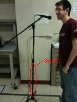
Boom Stand:
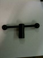
The parts that construct the boom stand are mainly constructed of either plastic or steel. Most of these parts are mass produced since stands are very common and high in demand. The few parts that plastic (handle and end of thumbscrews) along with the rubber ends on the bottom are most likely made through injection molding. Injection molding provides a high volume mass production of identical parts with very low tolerance. The initial tooling costs are very high but the unit costs are low (meaning a high initial fixed cost but in exchange the marginal cost per unit is sufficiently low), thus when a large quantity of identical parts are produced injection molding will save money in comparison to other processes.
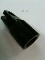
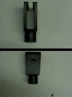
The counter weight on the end of the boom shaft and the microphone holder are both solid pieces of metal made through the casting process. The counter weight is then glued onto the end of the boom shaft. The casting process (my guess is die casting) has a similar manufacturing feature as injection molding cost-wise. They are generally a high volume production with high initial tooling costs but low unit costs.
Thing on bottom…..casting, plastic thing that was press fit into pipe
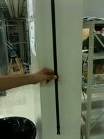
All the steel tube components have identical thicknesses and diameter, meaning that they can all be produced by the same machinery while each part is cut into the desired length. The raw steel is cast then made into a pipe by stretching the steel out into a tube. The steel tubes are seamless, which are suitable for the job as the shafts for being strong, durable, and light weight. The exterior of all steel components are sprayed on a metta-black finish for a good look to appeal to the consumers.
DFA:
The assembly of the parts can be either by man or machine. To our surprise, the after the stand was dissected and analyzed it took less than 5 minutes for a single person to reassemble everything part together.
Failure Modes and Effects Analysis
Considering ways in which a product could potentially fail is a crucial part of the design process. All products must be designed such that they are both safe and reliable for use and any potential dangers must be addressed in the design phase.
| Assembly/Parts | Failure Mode | Consequence of Failure | S | Causes of Failure | O | Prevention | D | RPN | Recommendations | Responsibility |
|---|---|---|---|---|---|---|---|---|---|---|
| On/Off Switch | Soldering Becomes Loose | Microphone will not turn on | 7 | Bad soldering | 2 | N/A | 2 | 28 | Check soldering before assembly | Controls engineer |
| Diaphragm | Torn Diaphragm | Inoperable | 7 | Misuse or Outside particles gets inside microphone | 1 | Foam Cover | 2 | 14 | None | N/A |
| Extending Stand | Grip fails | Stand does not stay extended | 5 | Wear from lots of use | 1 | Exploded end | 1 | 5 | Add rubber stoppers or grips | Design Engineer |
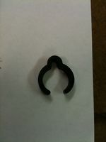
| Microphone Clip | Loose Joint | Unable to orient to desired location | 4 | Loose Screws, wear from use | 6 | N/A | 1 | 24 | Tighten Screws constantly, add friction to joint | Controls Engineer |
| Rubber Pads | Worn down thickness | Boom shaft is unstable, gravity overcomes friction force | 5 | Worn pads | 1 | N/A | 1 | 5 | Do not pivot shaft aggressively or unnecessarily | N/A |
| Rubber Ends | Torn or lost | Stand may slide | 2 | Worn down ends | 1 | N/A | 1 | 2 | None | N/A |
Design for Environment
In designing a product, it is important to consider the environmental effects along with the consumer. Conducting a Life Cycle Assessment (LCA) can improve the product's environmental-friendliness and reduce costs in the long run.
Toxic Release
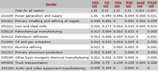
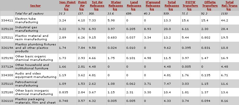
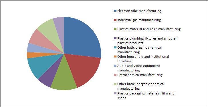
This table and graph show the amount of toxic release into the environment. Note that the amount released by specifically the manufacture of audio-video equipment is minuscule compared to the other sectors involved.
Greenhouse Gas Emissions
Greenhouse gases, such as carbon dioxide and chlorofluorocarbons, contribute to the prevalent problem of global warming. With a $1 million injection into the Audio-Video Manufacturing sector, the overall global warming potential (GWP) increase by 574 metric tons of CO2 equivalent.
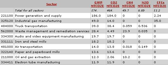
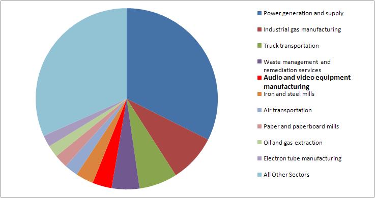 As we can see from the graph above, the actual audio-video manufacturing process only contributes 19.7 MTCO2E, less than 4% of the total. Most of the emissions come from power supply. If a CO2 tax was passed, the manufacture of audio-video might take a hit, but not as hard as most of the other sectors.
Air Pollutants
Conventional air pollutants such as carbon monoxide largely affect weather patterns like causing smog which in turn can cause respiratory and other health problem in affected areas. Most of the problem comes from power generation and the manufacture of petroleum. Audio-video manufacturing was not even in the top 10.
