Paintball gun
From DDL Wiki
(→How Product is Used) |
(→How Product is Used) |
||
| Line 160: | Line 160: | ||
While operating the markers, and trying to mark opponents without being marked themselves, users may perform intense physical activity such as running, jumping, diving and crawling. Some of this may include dirt, when done in an open forest-like area. This aspect of the product usage requires the most out of the marker. The marker must be durable enough to not get damaged, while having a constant supply of air and paintballs to fire in any orientation. | While operating the markers, and trying to mark opponents without being marked themselves, users may perform intense physical activity such as running, jumping, diving and crawling. Some of this may include dirt, when done in an open forest-like area. This aspect of the product usage requires the most out of the marker. The marker must be durable enough to not get damaged, while having a constant supply of air and paintballs to fire in any orientation. | ||
| - | The SPYDER MR1 Manual recommends the following official usage steps: | + | The SPYDER MR1 Manual recommends the following official usage steps and precautions: |
| - | + | http://www.spyder.tv/section/support/manuals/mr1.pdf | |
| - | + | ||
| - | + | ||
| - | + | ||
| - | + | ||
| - | + | ||
| - | + | ||
| - | + | ||
| - | + | ||
| - | + | ||
| - | + | ||
| - | + | ||
| - | + | ||
| - | + | ||
| - | + | ||
| - | + | ||
| - | + | ||
| - | + | ||
| - | + | ||
| - | + | ||
| - | + | ||
| - | + | ||
| - | + | ||
= Mechanical Analysis = | = Mechanical Analysis = | ||
Revision as of 23:45, 23 September 2007
Contents |
Executive Summary
Customer Needs
Most paintball players use their guns in tournament play at parks designed specifically for this purpose. On occasion, teams may play in uncharted forests or abandoned buildings to provide a new thrill and lower playing costs. The object of most games is to successfully shoot a paintball (the projectile) at an opposing team’s player to mark them with the paint inside the projectile. Speeds can reach up to 300 feet per second, over which the sport or play can become unsafe. Certain arenas measure and limit the users’ guns to a lower value. The first and foremost requirement is reliability and durability from a gun. There is nothing more frustrating than a gun malfunction in the middle of a game, when the user travels a significant distance to play. This quality can easily be found due to the strong correlation between price and durability. Having a good line of sight is paramount for aiming. Certain hopper and feeder designs go straight up from the gun housing, making it difficult to look at one’s target. For this reason, most designs incorporate an elbow feeder to offset the hopper towards the user. Barrel lengths will vary from 3 to 48 inches, and are usually interchangeable for a given gun. However studies have shown that no increased accuracy can be gained from a barrel longer than 8 inches. Lightness is a requirement for all levels of play, but again it is merely a question of price. Certain parts can be high strength plastics, sometimes even carbon, which would otherwise be of common metal alloys. The compressed air tank is perhaps one of the heaviest single parts on the marker. Carbon fiber is a popular alternative material for a tank, which may need to stand up to pressures of 5 ksi. More advanced users want quick adjustability of their projectile speeds. Bottom end markers require some tooling to change this setting, but more advanced markers, or aftermarket parts allow for on-the-fly adjustability even in the field. Typical low end markers use compressed CO2 (carbon dioxide), but this may cause inconsistent muzzle velocities. Advanced users will sometimes switched to compressed nitrogen, which eliminates this problem.
How System Functions
The paintball gun (or paintball marker) fires a 0.68 inch diameter paintball at speeds of around 280 fps using compressed air in a semi-automatic firing style. This means that after cocking the marker once, when you pull the trigger it will fire a paintball and also recock the marker for you. This allows the user to rapidly fire paintballs.
Before you can fire the gun, the bolt must be in the cocked position. This is accomplished by pulling the cocking pin back until you hear a click. This is only done once at the beginning of use. When the bolt is pulled back, the Venturi Bolt slides back in the marker barrel (shown in red) which allows a paintball to fall through the feed neck and into the marker barrel. The cocking pin is also connected to the striker bolt, which slides back in the striker chamber (shown in yellow) engaging the trigger mechanism (the trigger mechanism will be described separately in the next section). When the striker bolt engages the trigger mechanism, it is locked in the back position. This causes the striker spring to apply a force to the back of the striker bolt.
In this cocked position, the air reservoir (shown in blue) is filled with compressed air. This chamber is sealed off from the rest of the gun by the cup seal and valve pin assembly. This assembly is being pressed against the valve body (shown in green) by the valve spring. The valve body has three holes, one into the the air reservoir, another into the striker chamber, and a final leading up into the marker barrel. The valve pin extends through the valve body and into the striker chamber.
When the trigger is pulled, the striker spring pushes the striker bolt forward. The striker bolt strikes the valve pin, which opens the seal the valve pin and cap seal were creating with the valve body. Since the striker bolt and venturi bolt are connected, the venturi bolt also moves forward. Before the venturi bolt reaches the front position, it comes in contact with the paintball and pushes the paintball forward toward the barrel. Since the seal in the air reservior was opened, compressed air flows through the valve body into the striker chamber and the marker barrel. The compressed air that flows into the marker barrel accelerates the paintball out of the barrel, firing the paintball marker. The air entering the striker chamber forces the striker bolt back into the cocked position. At this point the valve spring pushes the cap seal and valve pin back against the valve body, sealing the air resevior again. With everything returned to the cocked position, another paintball falls into the marker barrel and the gun is ready to be fired again. The whole process from trigger pull until the gun cocks itself again occurs in less than a second.
Trigger Mechanism Function
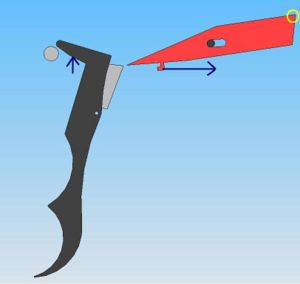
Since the trigger mechanism could not be disassembled, a CAD model of the system was created to allow a full understanding of the function of the system.
The trigger mechanism allows the user to control when the paintball is fired by controlling the release of the striker bolt. When the paintball marker is not cocked, the parts of the mechanism are in the configuration shown in Figure 1. The blue arrows show forces on different component applied by springs. The spring against the trigger (black component) forces this trigger back into this position when no other forces are applied. The spring against the striker lock (red component) forces the pin to be on the far left part of the slot (cut through the center of the striker lock). As you can see, when the trigger is pulled the trigger does not touch the striker lock.
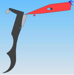
As said in the previous section, when the paintball marker is cocked the striker bolt "engages the trigger mechanism". This configuration of the trigger mechanism is shown in Figure 2. What this means is that the knotch on the bottom of the striker bolt "catches" the corner of the striker lock, outlined in yellow, applying a force to the left against the corner. This forces the striker lock to the left, sliding the pin to the right most position of the slot. This positions the left tip of the striker lock above the trigger.
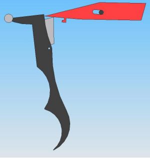
When the trigger is pulled, it rotates the striker lock. As you can see in Figure 3, the striker lock's right corner no longer points up out of the trigger mechanism. This rotations moves the striker lock out of the way, allowing the striker bolt to move forward and fire the paintball gun. Once the trigger is released, there is are no more external forces on the system and it returns to the equilibrium posisiton shown in Figure 1.
Components
**Note: Some assemblies and parts were not disassembled in order to avoid destroying the parts.
DFMA
FMEA
DFE
Opportunities for Improvement
How Product is Used
Markers must be stored in an ‘un-cocked’ position, with the safety switch in the ON position, no compressed air connected to the system, and with the barrel safety plug pressed into the end of the barrel. Most manufacturers require that moving parts be lubricated with the provided or recommended lubricants before each use. Caring users will disassemble several parts of their guns internals, to go through the lubricating steps. This will ensure longevity of the marker. Next, the user will check to have proper pressure in their gas canister, and an abundance of ammunition for the upcoming usage session. When users arrive to the arena, or playing area, overalls or certain special outer wear is put on by the users to attenuate the impact of the projectiles. A mask is the most important piece of protective equipment, guarding the eyes, face and sometimes ears from impact. Welt and ‘black and blue’ spots are common marks caused by being hit with a projectile. Most right handed users will hold the handle with their right hand, use their middle and/or index fingers to operate the trigger, and look down the length of the barrel with their right eye, with the left eye closed. While operating the markers, and trying to mark opponents without being marked themselves, users may perform intense physical activity such as running, jumping, diving and crawling. Some of this may include dirt, when done in an open forest-like area. This aspect of the product usage requires the most out of the marker. The marker must be durable enough to not get damaged, while having a constant supply of air and paintballs to fire in any orientation.
The SPYDER MR1 Manual recommends the following official usage steps and precautions: http://www.spyder.tv/section/support/manuals/mr1.pdf

