Talk:Toaster
From DDL Wiki
Client Response to Report 1
We received your report. From your summary, it seems that the most important finding is the opportunity to reduce part count to reduce complexity and assembly costs. Do you have specific ideas about which parts could be eliminated? Were there any other major findings or recommendations?
Specific comments follow:
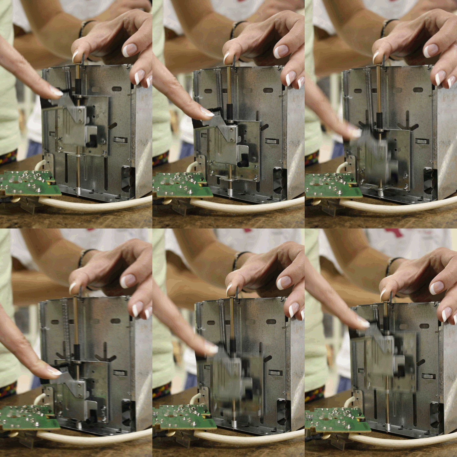
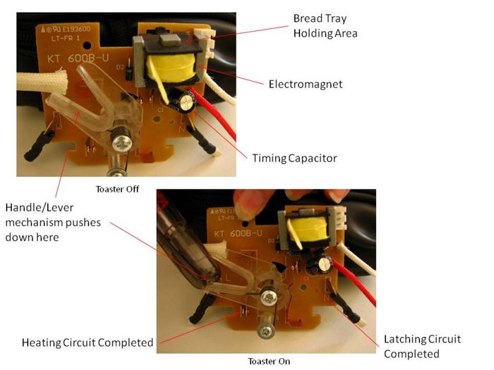
- Your description of the toaster function is interesting, but it is difficult to see all the details from the pictures you provided. Where does the handle interact with the switch mechanism? How are the circuits completed? What triggers the capacitor to discharge once its maximum voltage is reached?
- On the handle assembly, there is located a small trigger switch (19; refer to BOM). When the user presses on the handle to begin the toasting process, the trigger switch meshes with the slot in the switch mechanism (21), and pivots the switch around its spring loaded pivot point. The two copper contact points complete the circuit that powers the electromagnet, and this in turn holds the handle assembly down. The capacitor is the circuit breaker in this case. In the beginning, it is completely discharged. After the circuit is completed using the trigger switch, a current passes through the capacitor and begins to charge it. It takes a finite amount of time to become charged, after which, the voltage across the capacitor becomes constant. As the voltage is increasing over time, the current is decreasing, and finally becomes zero. Here is an equation which shows the voltage across a capacitor over time 't'.
This breaks the circuit, and thus deactivates the electromagnet, which in turn releases the handle assembly. The handle assembly, assisted by the restoring spring (15), returns to its original starting position. A few pictures explaining the whole process are posted below.
- Nice pictures in the user study. Are there any non-ideal use scenarios you did not consider (such as thick slices getting jammed, toasting bread that is too short, toasting crumbly bread, or loose pieces falling against the coils and burning)?
- We addressed the mechanical failure modes in our FMEA analysis. As far as non-ideal use scenarios go, these were addressed in Report 2 of this project. There we surveyed users in order to identify design problems and non-ideal uses associated with toaster use.
- Your stakeholder and user needs list seems incomplete. Please consider special users, like children, and examine additional important needs such as safety, ease of cleaning, adjustability, and ability to know what setting to use to obtain desired outcomes. Finally, please compile your list of needs into a bullet list.
- The stakeholders section of Report 1 has been updated as suggested. More specific stakeholders have been added, and the format has been changed to that of a bulleted list.
- Please include a picture of the assembly with parts labeled to help interpret the bill of materials.
- The Assembly section of Report 1 has been updated as suggested. Several pictures depicting key assemblies have been added and labeled.
- Why was aluminum chosen for part #2 if other parts are steel?
- Part #2 (the crumb tray) is not a structural component and, therefore, does not need to be able to endure the same kinds of stresses the other components do. The crumb tray is rarely moved and its failure will not effect the primary function of the device. The manufacturer probably decided that aluminum was fine for this application since it is not critical.
- Your DFM describes how parts were made, but do you have any conclusions about whether good DFM practices were followed? Your DFA observations about tabs for quick assembly without fasteners is interesting. Were other DFA practices followed well - e.g.: does all assembly take place from the same direction onto a base without obstruction where possible? It seems that it would be difficult to thread the bread shelves through the holes in the plates and secure them. What is the most difficult step?
- The DFM has been updated to include conclusions on DFM practices. The DFA section has also been updated to answer questions and suggestions. Not everything was assembled from the same direction, but the reason that there was very little obstructions was due to the step-by-step assembly process which carefully allowed certain pieces to be assembled before others.
- Your FMEA identifies fatigue as a failure mode. Is this from cyclic mechanical loading or thermal loading? Why did you assume a four year lifespan? What scale was used for your FMEA table?
- The FMEA has been updated to address these issues you pointed out. Basically, the fatigue failure mode refers to cyclic mechanical loading. The four year lifespan is explained briefly in the following comment. The scale used for the FMEA table can be found in the Engineering Design textbook by Dieter and Schmidt.
- Your DFE analysis is insightful, and the sectors you found seem representative. It looks like the dominance of the use phase will depend on frequency of use. How did you come upon the numbers you used? Also, you seem to have a mismatch in total GHGs from power generation and supply (you are considering only primary emissions and ignoring those from, for example, mining).
- The numbers used were all estimated based on moderate, regular usage of the toaster. Since the first report, we have reevaluated our estimate of usage per day. Previously, it was estimated that the usage would be about six minutes per day. However, after further user research, it appears that toasters are often used only one cycle per day. Cycle times range from a little over a minute to almost four, so our new estimate is three minutes per day. The four year toaster life was a collective estimate generated amongst our group. The consumer using a toaster frequently would likely purchase a new one before too long, either due to mechanical failure or simply a desire for something newer.
- The mismatch in GHG emissions and the change in usage per day, noted above, have been corrected (and the emissions recalculated) under the DFE section in Report 1. It did not change our conclusions from the DFE study.
- Why did you choose the question you did for the mechanical analysis? Isn't it obvious ahead of time that the shelf will not yield to the force of the weight of a slice of bread? What is the worst case force the shelf would encounter? What assumptions were made in your model? You provide only FEA pictures, but we cannot tell what assumptions were made on boundary conditions and why these are representative of the scenario. Why is this analysis useful - what do you conclude?
- The Mechanical Analysis has been updated as suggested. A more thorough and complete analysis of the shelf was conducted and discussed.
- Please comment on your process.
- A process description has been added under the Team Members and Process page.
We are looking forward to seeing your research findings and product ideas in the next report.
Client Comments on the Mechanical Analysis
In this report, the toast shelf is selected as the major component for an finite element stress analysis. The report pointed out that the failed toast shelf would make the toaster become a potentially dangerous appliance. However, I would like to see more explanations about why the toast shelf failure can cause such serious a problem because it is not included in your FMEA.
As a client, I would like to see more professional details in your analysis. The following information should be included:
- The finite element software and version you used for the analysis.
- The material property settings: for example, the values of tensile strength, Young’s modulus and poisson’s ratio.
- Please describe more about your boundary condition settings.
- The maximum applied force to cause the toast shelf failed.
- Plus, if the toast shelf material is aluminum, you may want to consider the offset effect on elastic limits if necessary.
- The report indicated that the long recess helps improve lateral stiffness. In order to demonstrate the difference, please provide the analysis results for the similar design without the recess.


