Umbrella
From DDL Wiki
(→DFM) |
(→Auto Open Close) |
||
| Line 213: | Line 213: | ||
| align="center" style="background:#f0f0f0;"|'''Picture''' | | align="center" style="background:#f0f0f0;"|'''Picture''' | ||
|- | |- | ||
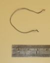
| - | | 1||Shaft||1|| | + | | 1||Shaft Spring||1||17.2||Causes the shaft to extend ||Coiled||Steel||[[Image:Umbrella_part1_shaft.jpg|100px]] |
|- | |- | ||
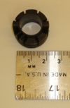
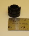
| - | | 2|| | + | | 2||Button||1||1.1||Releases umbrella mechanisms||Injection Molded||Plastic||[[Image:Umbrella_part2_handle.jpg|100px]] |
|- | |- | ||
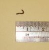
| - | | 3|| | + | | 3||Button Spring||2||0.1||Returns the Button to its original position||Coiled||Steel||[[Image:Umbrella_part3_tip.jpg|100px]] |
|- | |- | ||
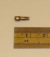
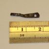
| - | | 4|| | + | | 4||Button Tab||1||0.4||Releases the String Bulb||Stamped||Steel||[[Image:Umbrella_part4_topCap.jpg|100px]] |
|- | |- | ||
| - | | 5|| | + | | 5||Button Tab Shaft||1||.3||Attaches Button Tab to Button||Formed||Steel||[[Image:Umbrella_part5_topCapRetentionPin.jpg|100px]] |
|- | |- | ||
| - | | 6|| | + | | 6||Button Tab Spring||1||1||Return the Button Tab to its original position||Coiled||Steel||[[Image:Umbrella_part6_topCapSkirt.jpg|100px]] |
|- | |- | ||
| - | | 7|| | + | | 7||Shaft Clip||1||1.2||Locks shaft in the collapsed position||Stamped||Steel||[[Image:Umbrella_part7_riderLimitPin.jpg|100px]] |
|- | |- | ||
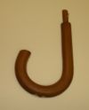
| - | | 8|| | + | | 8||Handle Frame||1||10||Houses and locates all of the handle mechanical parts||Injection Molded||Plastic||[[Image:Umbrella_part8_riderLatch.jpg|100px]] |
|- | |- | ||
| - | | 9|| | + | | 9||||2||<.1||Attaches rider latch to shaft||Extruded||Steel||[[Image:Umbrella_part9_riderLatchPin.jpg|100px]] |
|- | |- | ||
| 10||Canopy section||8||7.1||Keeps water from entering area below umbrella||Woven||Nylon||[[Image:Umbrella_part10_canopySection.jpg|100px]] | | 10||Canopy section||8||7.1||Keeps water from entering area below umbrella||Woven||Nylon||[[Image:Umbrella_part10_canopySection.jpg|100px]] | ||
Revision as of 16:34, 21 September 2008
Contents |
Umbrella
Basic introduction information. 'Contents' box is created automatically. To skip directly to a section, use Umbrella#FMEA to create a link.
Usage and Usability
An umbrella's primary purpose is to protect the user from rain, although they are also used in some cases to protect against sun or snow. To do this, an umbrella has a long, slender shaft with a handle on one end and a collapsible canopy on the other, coming to a point at the umbrella's tip.
The umbrella's protective canopy is extended as a rider, initially located near the handle, travels up the shaft towards the tip. In a standard non-collapsible umbrella such as ours, the rider's motion is started by releasing the rider latch on the handle end of the shaft and manually moving the rider upwards until the rider engages a second latch on the tip end of the shaft, locking the rider and canopy in place.
Some improvements on the standard umbrella design have been made to overcome some of the standard umbrella's flaws.
The rider mechanism in many umbrellas, such as the golf umbrella, is spring loaded to provide one-handed automatic opening. This is an improvement over the two-handed opening that the standard umbrella offers. The canopy must be forced closed and the spring must be manually reset after use.
Because an umbrella has a very specific intended usage - outside during rain - there are times when the umbrella will not be in use but must be carried for later use, such as indoors. It is beneficial to the user for the umbrella to be lightweight and have a small footprint when not in use. One popular variation on the standard umbrella is the purse umbrella. This umbrella has a hollow telescoping shaft that extends with a button press as the spring-loaded canopy is extended. The footprint of the umbrella and its weight are reduced substantially, enough that the umbrella fits conveniently into a purse or backpack and can be carried at all times. This decrease in size comes with an increase in component complexity, as the shaft cannot be a single piece of material and the arms must be folded as well. Additional joints are needed, and the overall strength of the umbrella is reduced. Like the golf umbrella, the purse umbrella must be manually closed to reset the spring.
The most complex variant on the classic umbrella is an automatically opening and closing umbrella. This extends the functionality of the purse umbrella by using an additional mechanism to automatically close the canopy with a button press. While the canopy is automatically closed, the spring must still be manually reset.
Even with these improvements over the standard umbrella, some issues remain unaddressed. All of the umbrellas designed for personal use must be carried by hand, and even the most complex umbrellas must be forced closed manually after use. This can be a difficult task for people with motor disabilities, such as Parkinson's disease.
Parts List
Major Stakeholders and Needs
DFA
Umbrellas are a high production part and as a result a great deal of effort has been put into design for assembly. With respect to assembly, the umbrella is broken into three sub assembles: the shaft, the arms and the canopy. By breaking it into these individual sub sections this arms can be assembled independently of the shaft which can be assembled independently of the canopy, saving assembly time. Design for assembly has been considered within each sub assembly by designing the joints and parts such that there are generous tolerances with respect to part location and by designing the joints such that they are easy to make. With respect to the arms, all of the joints except that connecting the Arm Support Rod to the Arm Joint Connector are crimped connectors to reduce assembly time and part count. Additionally, all of the 8 umbrella arms are identical which improves the ease of assembly and reduces the part count of the umbrella. With respect to the shaft, design for assembly has been considered in the use of identical components for the Upper and Lower Rider Latches. Making these components identical prevents confusion during assembly and the parts are designed such that they are simply hammered onto the shaft to reduce assembly time. Also, assembly tolerances were considered with respect to attaching the Handle to the Shaft. While glue is required for this joint, there is a large tolerance with respect to how deep the shaft has to be placed inside the handle, reducing the time that is required to assembly this joint. Along with being easy to assemble individually, the umbrella sections are designed to be easy to assemble to one another, with the arms attaching to the shaft using two pieces of wire. This attachment method makes it easy for the umbrella to be assembled quickly and simply.
DFM
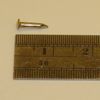
In order to reduce the manufacturing cost and effort the individual components of the umbrella have been designed with Design for Manufacture in mind. The majority of the metal parts on the umbrella are made through stamping premanufactured flat or round stock into the desired shape. This process is fast, efficient and removes the need for time intensive machining thereby dramatically reducing the associated manufacturing costs. Additionally by replicating components such as the Rider Latches and the arm components manufacturing costs are reduced. Similarly all of the plastic parts on the umbrella are injection molded for quick manufacturing time and reduced material cost. The umbrella also uses “off the shelf” fasteners where possible such as in attaching the top cap and upper hub to the shaft. Both of the fasteners involved in this assembly are standard brad nails which, because they do not need to be manufactured, reduce the cost of manufacturing the umbrella.
Here's an external link.
Here's an external link to a Excel to Wiki converter.
Here's the Wikipedia editing page. DDWiki and Wikipedia both run on MediaWiki software.
Here's an internal link back to the Main_Page. Using piping | lets you rename a link to, for example, the main page.
If you don't want something formatted, try using these HTML tags. Then you can put things like [[Main_Page]] into the document.
DFE
DFE analysis goes here.
EIO-LCA
This is for the EIO-LCA subsection of DFE.
FMEA
| Item or Function | Failure Mode | Effects of Failure | S | Causes of Failure | O | Design Controls | D | RPN | Recommended Actions | Responsibility |
| Shaft | Splintering | Decreased shaft strength | 5 | Wear | 3 | Coating or finish on shaft | 4 | 60 | ||
| Potential safety hazard to user | Material choice | |||||||||
| Durability testing | ||||||||||
| Breakage | Product is inoperable | 8 | Inappropriate stresses on shaft | 1 | Material Quality | 5 | 40 | |||
| Impact | Robust Design | |||||||||
| Rot | Reduced Strength | 3 | Poor Protective Coating | 1 | Coating Process Control | 5 | 15 | |||
| Handle | Splintering | Decreased handle strength | 7 | Wear | 4 | Coating or finish on handle | 4 | 112 | ||
| Potential safety hazard to user | Material choice | |||||||||
| Durability testing | ||||||||||
| Breakage | Product is inoperable | 7 | Impact | 1 | Material Quality | 5 | 35 | |||
| Robust Design | ||||||||||
| Rot | Reduced Strength | 3 | Poor Protective Coating | 1 | Coating Process Control | 5 | 15 | |||
| Tip | Loss of Protection | Degredation of Shaft | 2 | Wear | 4 | Material choice | 7 | 56 | ||
| Part Design | ||||||||||
| Top Cap | Corrosion | Decrease In Aesthetics | 2 | Oxidation | 2 | Material choice/Coating | 5 | 20 | ||
| Top Cap Retention Pin | ||||||||||
| Top Cap Skirt | ||||||||||
| Rider Limit Pin | ||||||||||
| Rider Latch | Bending | Latch fails to operate | 8 | Inappropriate Loading | 1 | Part Design | 2 | 16 | ||
| Jamming | Latch fails to operate | 8 | Corrosion/Foreign Debris/Poor Assembly | 2 | Tolerance control | 4 | 64 | |||
| Rider Latch Pin | Loss | Potential Loss of Latch | 5 | Vibration/Poor Assembly | 1 | Proper Assembly | 2 | 10 | ||
| Canopy section | Tear | Leak in Umbrella | 7 | Improper Manufacturing/Improper Storage by Consumer | 5 | Material Selection/Manufacturing Control | 4 | 140 | ||
| Seam Failure | Leak in Umbrella | 7 | Improper Manufacturing | 3 | Manufacturing Controls | 6 | 126 | |||
| Canopy Latch Strap | Seam Failure | Inability to strap umbrella | 5 | Improper Manufacturing | 3 | Manufacturing Controls | 6 | 90 | ||
| Canopy Latch Strap Velcro | ||||||||||
| Upper Hub | ||||||||||
| Hub Pin | Loss | Upper Hub not longer attached to shaft | 8 | Improper Tolerancing/Manufacturing | 1 | Proper Tolerancing/Manufacturing | 2 | 16 | ||
| Bumper | ||||||||||
| Connecting wire | Breakage | Arms disconnect from shaft | 8 | Wear | 1 | Coating/Material Selection | 6 | 48 | ||
| Rider | Button Breakage | Latch more difficult to operate | 6 | Fatigue | 2 | Proper Tolerancing/Manufacturing | 3 | 36 | ||
| Arm Mainshaft | Plastic Yielding | Deformed umbrella shape/trouble closing | 7 | Excessive Loading | 6 | Part Design/Material Selection | 4 | 168 | ||
| Arm Support Rod | Plastic Yielding | Deformed umbrella shape/trouble closing | 8 | Excessive Loading/Impact | 6 | Part Design/Material Selection/Manufacturing | 4 | 192 | ||
| Arm Support Rod Insert | ||||||||||
| Arm Endcap | Disassociation from Arm | Partial Canopy Detatchment/Exposed Rod | 7 | Insufficient Crimping/Tolerances | 5 | Manufacturing and Assembly Controls | 3 | 105 | ||
| Short string | Snap | Partial Canopy Detatchment | 7 | Excessive Loading/Defective Materials/Poor Manufacturing | 3 | Material Quality/Manufacturing | 5 | 105 | ||
| Arm Joint Connector | Plastic Yielding | Non-smooth operation | 2 | Excessive Loading | 2 | Part Design/Material Selection/Manufacturing | 2 | 8 | ||
| Seperation from Arm | Impaired operation of umbrella | 8 | Improper Manufacturing | 3 | Manufacturing and Assembly Controls | 3 | 72 | |||
| Arm Joint Connector Pin |
Here's a horizontal line
And another
They come free with section headings
Mechanical Analysis
Design Variants
Golf Umbrella
Purse Umbrella
Auto Open Close
The Auto Open Close umbrella is a double fold collapsible shaft variant of the standard umbrella which has additional mechanisms in order to allow it to both open and collapse with the touch of a button. The opening of the umbrella is achieved through a large spring which is compressed inside the shaft. When the open close button is pressed a latch releases the upper shaft, causing the spring to extend the shaft. At the same time the umbrella canopy is opened by a string which is latched inside the handle of umbrella. This string passes through the shaft, around a pulley at the top of the umbrella and is anchored inside the lower hub of the umbrella. By this means when the umbrella shaft is extended it causes the string to pull the lower hub upwards, extending the arms and opening the umbrella canopy. The collapsing of the umbrella canopy is achieved through tension springs located in each arm. When the open close button is pressed a latch attached to the button releases the string from inside the handle, this frees the lower hub, causing the tension springs in the arm to compress, collapsing the umbrella canopy.
