Umbrella 2
From DDL Wiki
(→FMEA) |
|||
| Line 282: | Line 282: | ||
====DFE Conclusion==== | ====DFE Conclusion==== | ||
Based on the results of the Life Cycle Assessment, | Based on the results of the Life Cycle Assessment, | ||
| - | |||
| - | |||
| - | |||
| - | |||
| - | |||
| - | |||
| - | |||
| - | |||
| - | |||
| - | |||
| - | |||
| - | |||
| - | |||
| - | |||
| - | |||
| - | |||
| - | |||
| - | |||
| - | |||
| - | |||
| - | |||
| - | |||
| - | |||
| - | |||
| - | |||
| - | |||
| - | |||
| - | |||
| - | |||
| - | |||
| - | |||
| - | |||
| - | |||
| - | |||
| - | |||
| - | |||
| - | |||
| - | |||
| - | |||
| - | |||
| - | |||
| - | |||
| - | |||
| - | |||
| - | |||
| - | |||
| - | |||
| - | |||
| - | |||
| - | |||
| - | |||
| - | |||
| - | |||
| - | |||
| - | |||
| - | |||
| - | |||
| - | |||
| - | |||
| - | |||
| - | |||
| - | |||
| - | |||
| - | |||
| - | |||
| - | |||
| - | |||
| - | |||
| - | |||
| - | |||
| - | |||
| - | |||
| - | |||
| - | |||
| - | |||
| - | |||
| - | |||
| - | |||
| - | |||
| - | |||
| - | |||
| - | |||
| - | |||
| - | |||
| - | |||
| - | |||
| - | |||
| - | |||
| - | |||
| - | |||
| - | |||
| - | |||
| - | |||
| - | |||
| - | |||
| - | |||
| - | |||
| - | |||
| - | |||
| - | |||
| - | |||
| - | |||
| - | |||
| - | |||
| - | |||
| - | |||
| - | |||
| - | |||
| - | |||
| - | |||
| - | |||
| - | |||
| - | |||
| - | |||
| - | |||
| - | |||
| - | |||
| - | |||
| - | |||
| - | |||
| - | |||
| - | |||
| - | |||
| - | |||
| - | |||
| - | |||
| - | |||
| - | |||
| - | |||
| - | |||
==FMEA== | ==FMEA== | ||
Revision as of 15:36, 6 February 2011
Contents |
Executive Summary
Major Stakeholders and Product Needs
Consumers
- Appealing
- Durable
- Lightweight
- Effective
- Safe
- Easy to use
- Portable
- Inexpensive
- Comfortable to hold
- Easy to clean/dry
Retailers
- Ease of storage
- Cost/Profit
- Durability
- Customer Satisfaction
Product Function
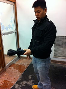
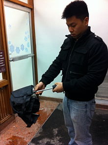
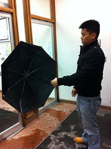
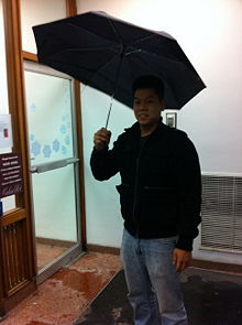
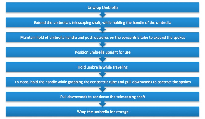
The operation of this particular umbrella was very simple. The pictures below depict the general use of an umbrella.
The umbrella consists of a handle which is connected to a telescoping shaft. The telescoping shaft is a mechanism that extends in order to expand several mechanical arms, or spokes, outward when the umbrella is in use. The extension of these spokes serves to expand the canopy, made of polyester, producing a dome shape. This dome shape deflects rain and snow from reaching the user. The concentric tube is located at the top of the shaft. It holds the spokes firmly together and is used to extend the telescoping shaft. There is a locking mechanism also located at the top of the telescoping shaft so that the canopy does not close when the user is holding the umbrella. To collapse the umbrella, the concentric tube is pulled downwards to shorten the telescoping shaft and contract the spokes. The umbrella is then stored.
To use an umbrella the following steps are taken:
Usability Study
After using this particular umbrella, numerous issues have been encountered. The polyester material is very loosely connected to the spokes. This results in an ineffective umbrella where the area of coverage from preciptation is decreased. Furthermore, the spokes of the umbrella was observed to have many moving parts. The outcome is a sacrifice in strength. A common outcome is bending of the spokes due to excessive winds. We noted that a stronger mechanical design for the spokes was needed for the umbrella. Additionally, precipitation contacted the user during use when high winds was present. During our study, snow reached the user in a direction perpendicular to the position of the umbrella. This also diminished the effectiveness of the umbrella. Finally, storing and cleaning the product was a major issue. It was observed that after use, many users commonly shake off the excess water from the umbrella onto the floor of the location they enter.
Bill of Materials
Assembly Diagram
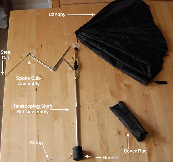
The image below depicts the major components of the product.
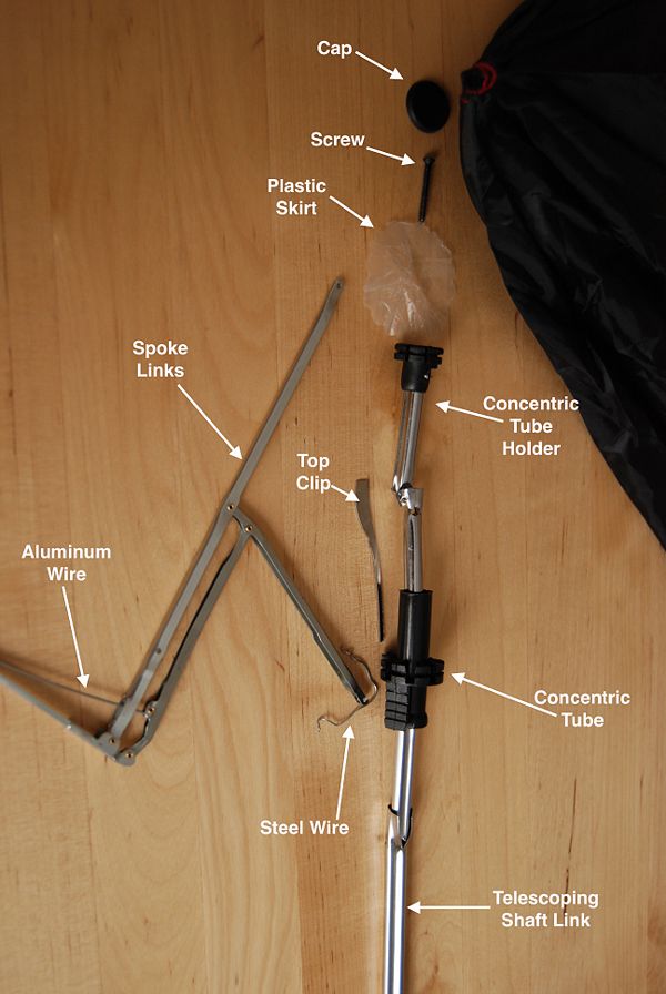
The image below shows a more detailed look at the more intricate portion of our product.
Design for Environment (DFE) Analysis
When creating a product, engineers must address the potential impact on the environment during the development process. A Design for Environment, DFE, analysis was conducted by our group. We aimed to identify the environemental impacts by utilizing an Economic Input-Output Life Cycle Assessment (EIO-LCA) of an umbrella. Furthermore, we also strive to determine the impact on the cost of production if Congress were to pass a tax on the CO2. This was accomplished using Carnegie Mellon’s EIO-LCA website. We calculated the greenhouse gases and toxic releases associated with our product, assuming $1 million dollars of ecnomic activity was used in the sector: #33299C: Other fabricated metal manufacturing. We have decided that this sector best contains our product as it includes the main material used in life cycle of the product: aluminum. Although our product contains textile components, we have chosen not to consider the textile manufacturing sector as our product contains mostly aluminum by weight. During our analysis, we concluded that there were no known energy inputs during the use phase of the life cycle assessment. Therefore, we have chosen to disregard an examination on the potential impacts on the enviornment from umbrella usage. The results from using the EIO-LCA website are summarized in the following tables. The energy in Tera Joules (TJ), emission of greenhouse gases, in metric tons of CO2 equivalent (MTCO2E), and toxic releases from the top 5 contributors of the production phase of the product are shown below.
Energy
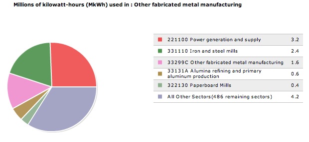
The table below shows that when an additional 1 million dollars is spent in the sector, Other fabricated metal manufacturing, there is an increase of 12.5 TJ of energy.
The results show that the majority of this increased energy is produced by Power Generation & Supply. Approximately 25% of the increased energy is derived from this sector.
Greenhouse Gases
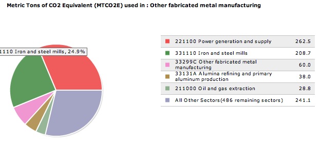
The table below shows that an additional 1 million dollars spent will result in an increase of 839 metric tons of CO2 Equivalent (MTCO2E).
The results indicate once again, the large role of the Power Generation & Supply sector. This sector is responsible for nearly 31% of the increased emissions. However, the sector that contains our product has a smaller role. The Other fabricated metal manufacturing sector contributes about 7% of the increased emissions.
Toxic Releases
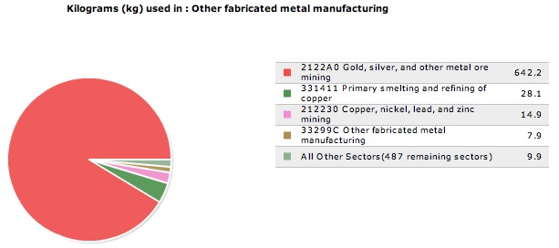
An additional 1 million dollars spent in the sector, Other fabricated metal manufacturing, will also result in an increase in toxic releases by 703 kg.
Results of our analysis indicate that the Gold, silver, and other metal mining sector is responsible for an overwhelming 91% of the increase in amount of toxic releases. The sector, Other fabricated metal manufacturing, is only responsible for approximately 1% of the increased toxic releases.
Life Cycle Assessment (LCA)
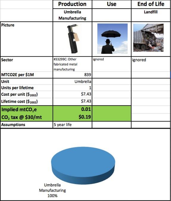
The emissions associated with umbrella manufacturing from the sector: #33299C: Other fabricated metal manufacturing are presented in the table below. The table also shows what the implied CO2 tax will be assuming Congress passes a tax of $30 per metric ton equivalent of CO2. Again, we concluded that there are no known energy inputs during the use phase of the life cycle assessment, aside from that of the user. Therefore, we have chosen to disregard umbrella usage from the life cycle assessment.
DFE Conclusion
Based on the results of the Life Cycle Assessment,
FMEA
| Item and Function | Failure Mode | Effects of Failure | Causes of Failure | Design Controls | S | O | D | RPN | Recommended Actions |
|---|---|---|---|---|---|---|---|---|---|
| Handle - Allows for user to hold umbrella | Fracture | Cannot hold product and potential danger | Impact | Material Strength | 7 | 2 | 1 | 14 | Use stronger material |
| Telescoping Shaft Sub-assembly - Extends and contracts the umbrella for portability | Fracture | Product inoperable and potential danger | Impact | Material strength | 9 | 4 | 1 | 36 | Use stronger material |
| Rust | Poor Aesthetics | Corrosion of material | Material Coating | 3 | 3 | 3 | 27 | Use better coating | |
| Concentric Tube - Holds the spokes and ribs in a circle and opens/closes umbrella | Fracture | Product inoperable - Spokes cannot be held in place | Impact | Material Quality | 7 | 2 | 2 | 28 | Use different material |
| Spokes Sub-assembly - Holds the canopy in a dome shape | Bend/Twist | Cannot hold canopy in place properly | Impact and wind resistance | Manufacturing | 9 | 8 | 1 | 72 | Redesign linkage and use stronger material |
| Cap - Holds canopy in place and prevents water from leaking | Fracture | Water will leak from top | Impact from dropping | Material Strength | 3 | 5 | 4 | 60 | Use metal instead of plastic |
| Steel Connecting Wire - Holds the Spokes and conenctric tube together | Fracture | Umbrella will be ineffective | Fatigue and wear | Durability Testing | 7 | 2 | 3 | 42 | Use stronger material |
| Top Clip - Prevents the concentric tube from falling down the shaft | Bent/Fracture | Will not be able keep the umbrella open | Impact | Material Strength | 6 | 3 | 3 | 54 | None |
| Canopy - Covers the user from rain | Rip/Tear | Water will leak onto user | Impact/extended use | Durability Testing | 8 | 9 | 1 | 72 | Use stronger textile |
| Steel Cap - Holds Spokes sub-assembly and canop together | Fracture/Bend | Will not be able to extend canopy | Extended Use | Durability Testing | 5 | 2 | 3 | 30 | Redesign steel cap |
