Water pump
From DDL Wiki
| Line 105: | Line 105: | ||
http://www.greatriverenergy.com/aboutus/pressroom/doc101349.pdf | http://www.greatriverenergy.com/aboutus/pressroom/doc101349.pdf | ||
http://www.eia.gov | http://www.eia.gov | ||
| - | |||
| - | |||
| - | |||
| - | |||
| - | |||
| - | |||
| - | |||
| - | |||
| - | |||
Revision as of 22:31, 24 September 2012
Contents |
Executive Summary
Primary Stakeholders and Product Needs
The major stakeholders are the customer and the shipper. In the typical American urban household, the main use of this type of pump is to pump water out of basements or to water grass. To meet these needs the product has to be able to pump water from a lower source, the basement, to a higher final place, such as through a window and outside into the grass. It has to be durable and simple to use which means that anyone can use it. The shipper needs the product to be as light and small as possible to cut down on weight, which cuts fuel costs. Also smaller products mean that more can fit in the same space and also reduce shipping costs. These two groups are the main stakeholders of the post production section.
Product Use
How the Product Functions Mechanically
First plug in the motor with the appropriate voltage selected. The electricity runs through the pressure sensor and then to the motor. The motor turns an internal shaft which is connected to a buffer spring. The spring is connected to the impeller which is connected to an nozzle that goes to the inlet. So the motor shaft, spring, impeller, and nozzle are all connected into one shaft driven by the motor.
When the motor turns it creates a suction which draws the water through the inlet and nozzle to the impeller. The spinning impeller then throws the water out into the iron chamber causing a vortex to develop. This vortex then causes the pressure to increase inside the iron chamber and forces the water through the outlet. It is the pressure created from the spinning water that is actually pumping the water.
The pressure sensor is connected to the iron chamber and when the pressure reaches a certain threshold, it causes a mechanical switch to cut the power to the motor. The pressure sensor threshold can be adjusted by setting a spring to a predetermined compression. Then when the pressure increases it compresses the spring more, which will cause the circuit to break through various mechanical linkages.
Bill of Materials
Design for Manufacture and Assembly (DFMA)
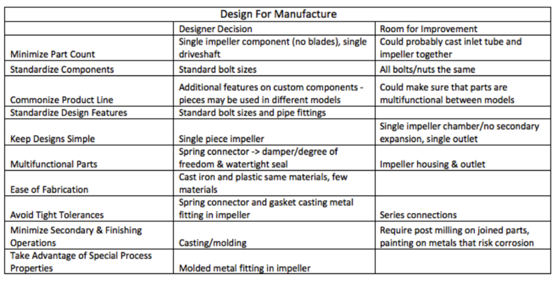
Design for Manufacture
The pump features a simple design with a single impeller, which enables the pump to accomplish the task at hand in the least number of parts for simplest manufacture. Cast iron and plastic are the primary materials in the device, as use of fancy materials is not necessary for the pump. The table below outlines in more detail the designers’ decisions to make the manufacturing process simpler, and areas where the process could be improved.
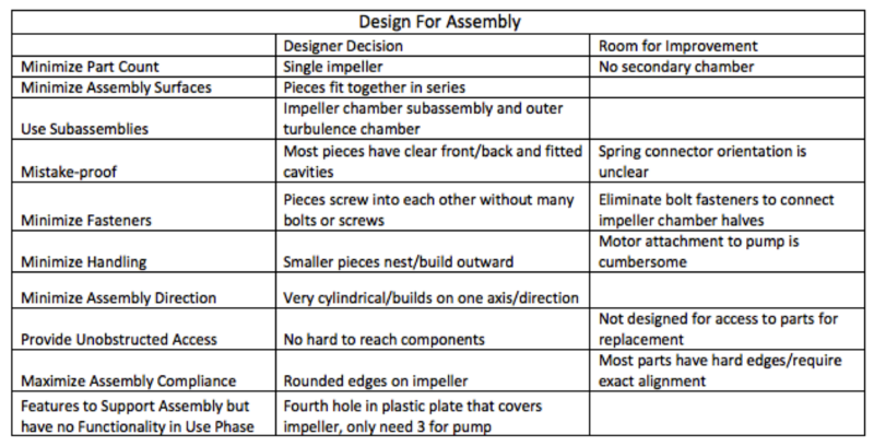
Design for Assembly
The parts of the pump assemble in series, and most pieces screw into each other with excess fasteners. The components have obvious front/backs for easier assembly. Standard bolt sizes and pipe fittings are a wise choice because it eliminates any need to acquire specialized fasteners. The table below outlines in more detail the designers’ decisions to make the assembly process simpler, and areas where the process could be improved.
Failure Mode and Effects Analysis (FMEA)
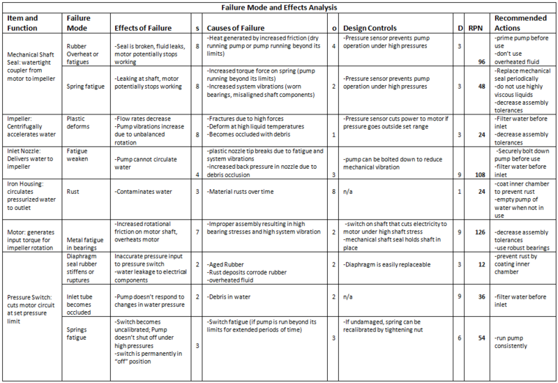
Because of the number and complexity of system components, a typical single-stage, mechanically coupled centrifugal pump can fail in approximately 600 ways (Mechanisms). To narrow pump failure modes to the most likely component failures, it was assumed that the most likely causes of pump failure would take place in the moving parts of the system, located along the shaft. The stationary components were assumed to be less susceptible to fatigue and stress failure, unless noted in the dissection and use study as in the case of the inlet nozzle and pump casing.
The inlet nozzle, the motor, the pressure switch and the mechanical shaft seal were determined to have the highest combined RPN value. The inlet nozzle is crucial for pump function and was observed to fail under long term use. The motor is the most complicated assembly and can be dangerous if it fails due to overheating or if water leaks in. The pressure switch and the mechanical shaft coupling both have multiple modes of failure and can easily become fatigued or broken with pump misuse.
It was noted during the dissection and use study that the tip of the inlet nozzle was broken off inside the housing, indicating fatigue as a mechanism of failure for the nozzle. The inside of the pump housing chamber was extremely rusted and the water circulated through the pump became contaminated, which is a system failure for intended use as a well pump.
To prevent overall component failure, it is most important to properly assemble the pump and have narrow tolerances, particularly on the shaft components because a misaligned component will be subjected to high stresses and causes vibrations in the system. It is also important to prime the pump before use because mechanical seals will overheat and permanently fail due to increased friction. Debris in the water is a cause of multi-component failure because an occlusion in any part of the pump will result in high system pressure. The addition of a filter and rust-prevention measures, such as internal coating or an easy way to empty the pump of water would be beneficial to include in redesign. It would also be beneficial to redesign the pump such that it is easy to disassemble and replace fatigable parts, such as the shaft seal. However there are trade-offs because the addition of these design changes would increase system cost.
Design For Environment (DFE)
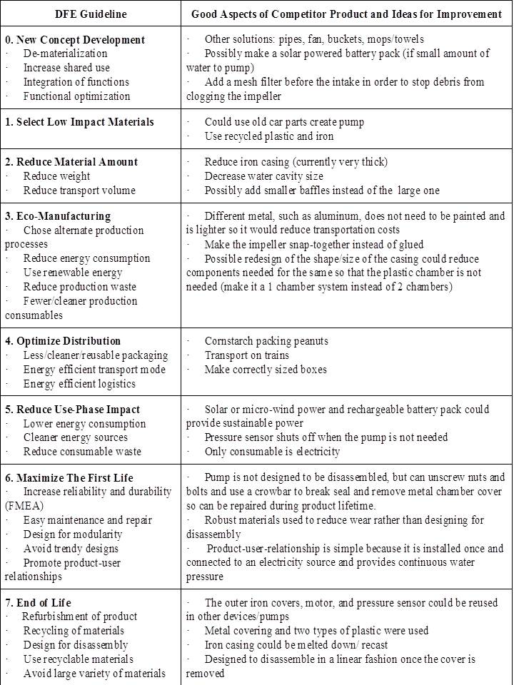
The DFE analysis showed that the pump system can easily be recycled and does not waste many materials. The motor and pressure sensor do not appear to be specifically designed for this system and so they could potentially be used in other products. The pump’s iron casing can be recast and the plastic parts can be recycled. The entire system was not built to be disassembled because it is difficult to take apart and a seal has to be broken in order to fix any internal parts. The chosen materials are robust, therefore it seems that it was meant to last a long time without failure, but not be fixed after breaking. There are several suggestions for improving the design. Possibly make the pump solar powered or have a battery pack that could be charged using solar power. The iron casing could be made thinner as the current component could withstand extraordinary pressures. Also instead of using iron, aluminum would still be strong enough and since its lighter, would cut down on shipping costs. The pump could be redesigned to only have one chamber, which would cut down on materials, assembly time, and shipping costs.
EIO-LCA
The pump we dissected is no longer on the market. However similar pumps cost approximately $200.00 - $300.00 and have an average warranty of 1-3 years.
Great River Energy, a Minnesota and Wisconsin Energy Cooperative, estimates that farm house well pumps draw between 7 and 108 kwh/month. Since a half-horsepower shallow-well pump is at the low end of the power spectrum, we assume that the average power use is under 10kwh/month.
The year to date national average residential electricity cost per kwh is $0.1179 as of June 2012 according to the US Energy Information Administration.
From this, we estimate the total energy use cost of this pump over a conservative lifetime of 3 years to be $42.44.
When the pump is installed, it is necessary to dig a well, install a holding/pressure tank and plumb the associated farmhouse. However, these expenses are not dependent on the type of pump used and are therefore neglected in this analysis. The pump is drawing ground water from the land of the pump owner, so there are no significant ongoing costs during the lifetime of the pump.
The two main industries the pump falls into are therefore “Pump and Pumping Equipment Manufacturing” (Sector # 333911) and “Power Generation and Supply” (Sector # 221100).
Using the EIO-LCA analysis tool we found that 530 Tons of CO2 are generated per million dollars of goods purchased in sector 333911 and 9370 Tons of CO2 are generated per million dollars spent in sector 221100. With our inputs of about $300.00 and $42.44 respectively, that amounts to CO2 outputs of 0.159 Tons and 0.398 Tons respectively. This ratio of production emissions to use emissions is rather high for electricity intensive appliances and indicates that increasing the pump’s useful lifetime and improving the efficiency of production could produce a significant percent reduction in the CO2 emissions associated with the lifecycle of the product.
A $30.00 / Ton tax on CO2 emissions would increase the purchase price by 4.77 and the use-cost by 11.92 over three years for a product lifetime cost increase of $16.70 or 4.9%. This is not expected to have a significant impact on consumer choices.
Since a carbon tax would raise electricity prices significantly, consumers may justify purchasing more efficient appliances across the board, but the increased use-cost of this pump is actually not that large.
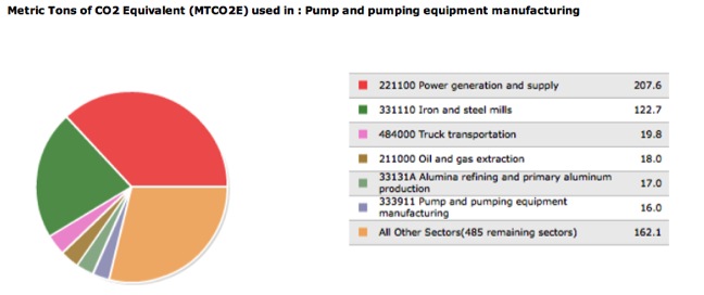
For the production section of the pump lifecycle, the primary contributing sectors to GHG emissions are Power Generation and Supply, Iron and steel Mills, and Truck Transportation, which are all indirect emissions sources. Pump and pumping equipment manufacturing is only the sixth highest contributor to GHG emissions with 13.4 tons CO2 emitted per million dollars purchaser input.
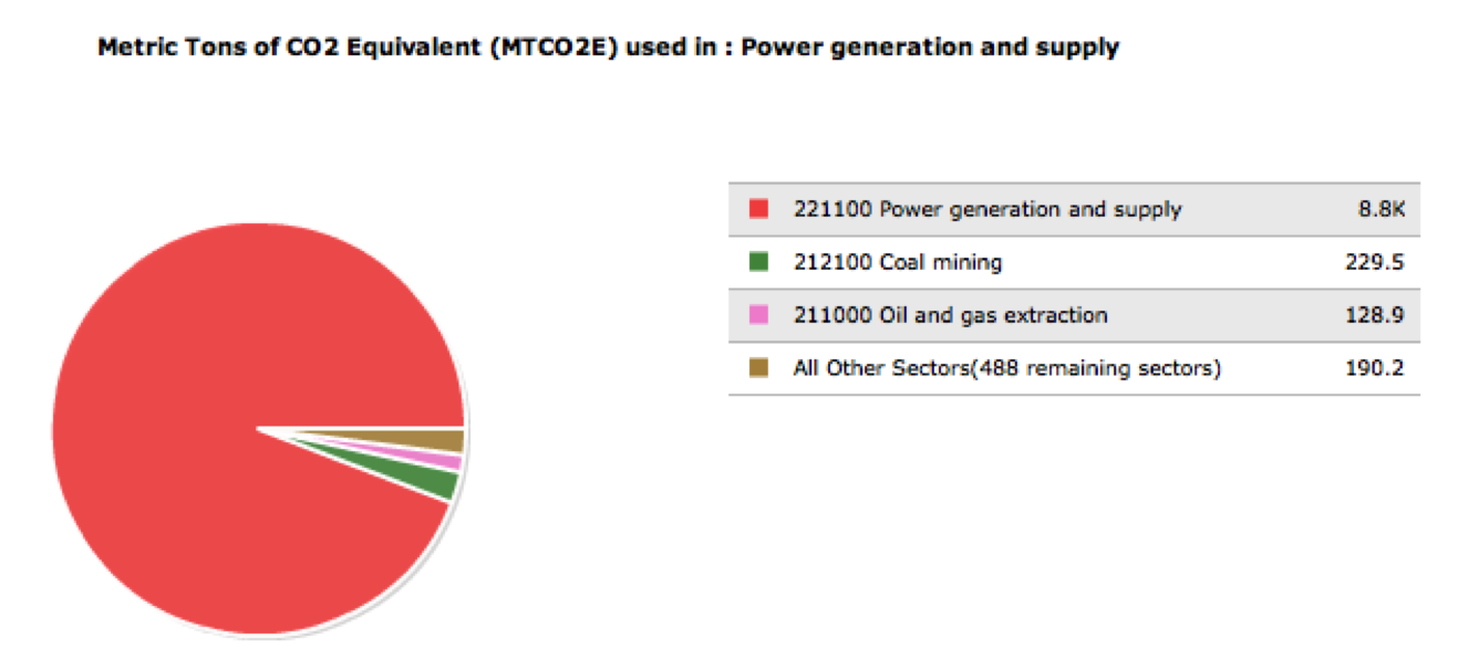
In contrast, during the pump’s use the vast majority of GHG emissions are directly from power generation and supply, the sector that provides electricity to run the pump.
The two selected economic input sectors are assumed to be a very good representation of the costs associated with our product because both are narrow (do not represent significant aggregation uncertainty) and effectively describe the product and lifetime use-input. In both power generation and supply, and pump and pumping equipment manufacturing, the product falls in at least half of the sub-sectors of the aggregate sector.
Team
Team Leader: Jerry
DFMA Leader: Kyra
FMEA Leader: Jenny
DFE Leader: Christina
Life Cycle Analysis Leader: Eva
The use study and dissection were collaborative as well as the slide presentation, executive summary and conclusion articles. Christina wrote the stakeholders article, how the system functions mechanically section, part of the DFE summary and DFE table. Kyra wrote the step-by-step instructions, DFMA summary and the DFMA table. Jerry wrote the bill of materials and labeled the components. Eva added, cropped and labeled the product pictures, conducted the life cycle analysis, and wrote part of the DFE summary. Jenny took the product pictures, wrote the FMEA summary and the FMEA table. To coordinate with each other, we met frequently and used google.docs to compile the final report. The process started with researching pumps, how they work and their uses. We then conducted a use study, then the dissection, division of the various engineering tables/guidelines, wrote the slides, and compiled the report.
References
List of 600+ Mechanisms of Pump Failure. http://www.lifetime-reliability.com/free-articles/reliability-improvement/pump-failure-modes-list.html
How to Adjust Water Pump Pressure Control Switch. http://inspectapedia.com/water/WaterPumpAdjust.htm
Mechanical Shaft Seals for Pumps: http://net.grundfos.com/doc/webnet/waterutility/_assets/downloads/shaft_seals.pdf
Electric Motor Failure Modes. http://blog.machineryhealthcare.com/bid/47114/Electric-motor-failure-modes
Household Uses: http://www.plumbers-inpittsburgh.com/uses-of-a-water-pump-that-you-should-to-know
LCA: http://www.eiolca.net http://www.greatriverenergy.com/aboutus/pressroom/doc101349.pdf http://www.eia.gov
