Ceiling-mounted storage lift
From DDL Wiki
This article was contributed as part of a design project for the course 24-441 Engineering Design in the spring semester of 2007 at Carnegie Mellon University.
Team 1 - Report 1: Ceiling-mounted bicycle lift
Team 1 - Report 2: Ceiling-mounted bicycle lift redesign
Contents |
Executive Summary
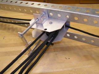
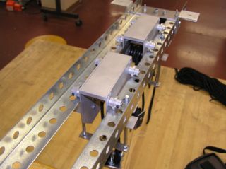
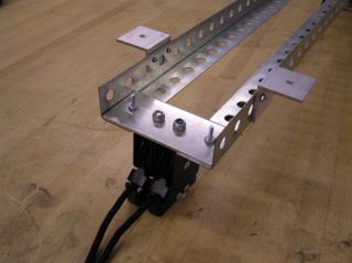
This design for the ceiling-mounted storage lift is the product of our work from January 2007 to May 2007. We performed market research to recognize opportunities to improve upon the ceiling-mounted bicycle lift. Our market research exposed a need by consumers to store a wide array of items besides a bicycle. After several brainstorming sessions and initial design concepts, we chose to design a product that increases the functionality of the lift to fulfill this consumer need. The ceiling-mounted storage lift exhibits several features that improve upon the bicycle lift. Our new design features ceiling brackets that move along a track and lock into place rather than being screwed into a single permanent location. This allows the user to adjust the length between the upper pulleys to account for different sized objects. The new design also features interchangeable attachments that will be specifically made for different types of objects. Packages will be sold separately from the generic hooks and straps and will include a sports package, a clothing package, a garage package and a universal package.
The ceiling-mounted storage lift is designed very effectively for manufacture and assembly. The number of custom parts is very low and most of these parts are manufactured by stamping and bending of steel sheet metal. Many of the parts we used in our design are already in production and may simply be purchased rather than building new machines to manufacture them. The minimization and duplication of parts in our design also aids in assembly of the product.
With safety as a primary concern, we designed the ceiling-mounted storage lift to have a non-catastrophic primary failure mode. Primary failure occurs as slippage of the rope through the locking mechanism at an unlikely high load of 480 pounds. All other components of the product are designed to withstand much higher loads to ensure that the primary failure mode is slippage of the rope.
User testing of our final prototype showed some promising results but also exposed a few usability issues. We believe that our product should be pursued for production and we conclude that the remaining issues can be resolved with more user-testing on a further refined prototype.
Project Background
For our senior capstone design project, we were to work in groups to analyze a current product on the market with some engineering involved in the design. Our group of four decided to analyze a ceiling mounted bike lift. For the project, we were to fully understand the functionality of the product and dissect it. Then we were to find opportunities by brainstorming where we could enhance the product or its functionality. Finally, we were to build several prototypes demonstrating our ideas and improvements to the current design.
With our selection of the ceiling mounted bike lift, we found several opportunities where we could improve and change the current design. These improvements include increasing the functionality of the lift, allowing the user more flexibility in the usage of the lift, increasing the maximum lift load and diversifying the product from its competitors on the market. This project has allowed our group to work across several business lines from engineering to marketing to production. The project concluded with our presentation of our final prototype. The details of our opportunity, findings, analysis, design and conclusions will follow.
Opportunity & Market Research
We believe that a universal, efficient ceiling-mounted storage system would be extremely helpful to the general public. The system that we designed can dramatically decrease the amount of clutter and disorganization that so often fills closets, garages and basements. Fortunately, the general public agreed with our assertions. From a survey that we conducted on the campus of Carnegie Mellon University, an overwhelming 85% of those surveyed expressed a desire or interest in a product like ours. Also, 57% surveyed said that they would be willing to spend between $10-25 on a lift, while 27% said that they would be willing to spend between $26-50. These results are very important because they are right inline with our price point. We are prepared to market our base product for around $25-35. Additionally since most of the users surveyed were college students, the average customer most likely would be willing to spend more because they have significantly greater income than most college students. This leads into an interesting marketing approach that we plan to take.
Most of the users surveyed expressed an extreme interest in using the lift to store clothes and shoes out of the way. Also, users were interested in seasonal objects, sports equipment and typical garage items such as gardening equipment. This provides us with the opportunity to market several product families under a single brand name. First, we plan to offer the ceiling-mounted storage lift equipped with hooks and clips to store bikes as the lift was traditionally meant for, as well as the wide array of items that can be stored with the hooks. Most importantly however, we are prepared to offer the user several packages that can be purchased along with the lift to satisfy every user's needs. This allows us to price the base unit lower, around $20, and charge more for our additional packages. These packages include:
-A sports package that incorporates hooks for various equipment (baseball bats, hockey sticks, etc), straps for kayaks and skis, loops for different sized sports balls and more.
-A clothing package that consists of fabric shelves for clothes and shoes as well as a rack from which clothes can be hung.
-A garage package that allows the user to place hooks on a peg board to fit garden tools, shovels, rakes, and other tools. The user can then hoist the peg board to the ceiling so that a car can easily be parked in the garage.
-A universal system of buckets and bins so that users can throw anything they want off the ground into them and clean up the clutter that haunts many peoples houses and lives.
Product Description
Components
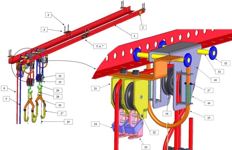
The Ceiling-mounted storage lift BOM contains the quantity of each component in this product, the weight of that component, its function, the material it's made of and its most likely manufacturing process. It also contains both a CAD image and a dimensioned drawing of each custom part and a catalog reference for each purchased part. The design is comprised of 121 total parts with 29 unique parts. The total weight is 4.1 kilograms or approximately 9 pounds. The ceiling mounted storage lift has been designed to use a minimal number of parts while still being capable of its desired functionality. The DFMA section of this report includes further detail on some of the considerations that were made in designing many of these parts.
Pre-Packaging Assembly
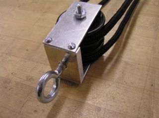
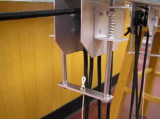
There are three major sub-assemblies that need to be assembled prior to packaging and shipping of the product. The remainder of the assembly process is to be completed by the consumer. These major assemblies can be seen below: the sliding bracket(1), the lower bracket(2), and the rope locking bracket(3). Please follow the link next to each image for a detailed description on how these components are to be assembled.
1: Storage Lift Sliding Bracket Assembly
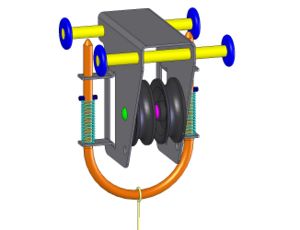
2: Storage Lift Lower Bracket Assembly
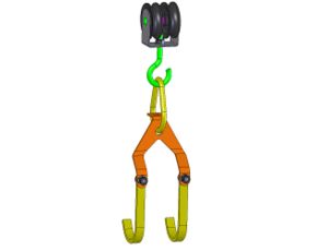
3: Storage Lift Locking Bracket Assembly
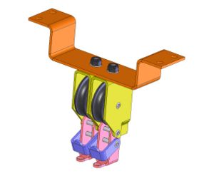
Consumer Assembly
Please refer to the Storage Lift Consumer Assembly page for a detailed description of the steps the consumer will need to follow to properly install the product. We put a considerable amount of thought into our design to make this process as simple as possible, while not diminishing any of the product's features. Our DFMA section dissuses these design considerations in greater detail.
Engineering Analysis
Design for Manufacture and Assembly (DFMA)
Summary
Our DFMA analysis concluded that this product is designed very effectively for manufacture and assembly. The number of unique parts is very low and very simple techniques are used to make these parts, almost exclusively from the same material. There does exist a few areas in which the design could be considered sub-par, specifically with regards to assembly, however when aspects such as functionality and cost are brought into play, it becomes apparent that this design is well optimized.
- Please refer to the DFMA page for a more detailed description of tools, methods and proccesses used in analyzing a product in terms of design for manufacture and assembly.
Manufacture
In designing the ceiling-mounted storage lift, we employed many of the same DFM techniques that were used to design the ceiling-mounted bicycle lift. Minimizing the number of unique parts lowers production costs by reducing the amount of new machines and tooling to create those parts. Minimizing the total number of parts also reduces costs for raw materials as well as reduces weight and keeps transportation costs low. The ceiling-mounted bicycle lift minimized parts well with only 19 unique parts and 66 total parts. We greatly increased the functionality and complexity in our design while only increasing the number of unique parts to 29. The total number of parts in our design is 121. When possible, we incorporated duplicate parts and subassemblies in our design. For example, the upper and lower bracket assemblies appear twice and are identical. The ceiling mounts are also identical with one mount having two identical locking mechanisms attached. The only non-duplicated part in the design is the single wall rope tie.
In addition to keeping the number of unique parts to a minimum, it is also cost effective to use parts that are already in production for other products and may be purchased. This eliminates the cost of creating new machines. Of our 29 unique parts, 18 are parts that are already in production and may be purchased. Of the 11 parts that must be custom built, there are only 4 parts that are not already custom built for the ceiling-mounted bicycle lift. Ten of the eleven custom parts are stamped and bent from steel sheet metal. The remaining custom built part is the aluminum U-rod that is manufactured using the common manufacturing process of extrusion and then bent into shape. The only post machining for the U-rod is to cut a taper on the ends of the rod. By using the manufacturing process of stamping for almost all of our custom parts, we eliminate the need for any post machining. We designed the stamped parts this way to make them very cost effective to be produced in high volume. Stamping will create some waste material, but this material can be gathered and recycled to create more parts. Overall, we feel that the design for the ceiling-mounted storage lift does not require any costly or complex manufacturing processes and is well suited for mass production at low cost.
Assembly
The reduction of total parts and use of duplicate parts as discussed previously from the fabrication standpoint are also beneficial for assembly, since less steps are needed for both the producer and consumer. Also, with less unique parts to sift through, it makes for a much more effiecient assembly process. Along these same lines, the incorporation of distinct sub-assemblies creates a more modular design adding to the overall ease of assembling the product. Many of the sub-assemblies, such as the sliding bracket and the lower bracket assemblies are also duplicates, further increasing the ease of assembly. Parts such as the ceiling mount, channel mount and lower bracket were made with obvious symmetry to effectively eliminate the oppurtunity for improper installation.
One of the bigger improvements that we made with our design over the existing bike lift design was with regard to the amount of fasteners. We added a significant amount of functionality in our new design but managed to cut the number of unique fasteners by roughly half. The total number remained roughly the same, but we were able to incorporate a design that only required the use of a single type of bolt for the majority of our metal fastening. As with the bike lift one of the biggest shortcomings of the product with respect to assembly is the accessibility of certain parts when attempting to fasten them, for example, the lifting ropes. The double pulley arrangement makes the rope installation slightly more complex and difficult, however we feel it was necessary to allow for the product's increased versatility.
Design for Usability (DFU)
When putting together the details of the design of this product, we found that the increased functionality tended to lead to a product with decreased usability. We are aware of the influence that usability has over the prolonged success of a product and sought to make this product as intuitive as possible.
One of the design decisions with the biggest impact on usability in this product is the various rope locations. We realized that the most common time for the user to want to reposition the sliding brackets is when they are actually attaching the item to be stored. So with this in mind we positioned the rope that controls both sliding and locking/unlocking adjacent to the lifting attachments. We used a unique color for these ropes, so as not to be confused with the lifting ropes. We also sized the springs that control the locking so that a weaker user would have no difficutly operating the lock, yet we sized them strong enough to give a definite feel of being in either the locked or unlocked position.
We incorporated caribiners into our interchangeable attachment design to solve several usability issues. First of all, most people have not only seen a caribiner function, but are fairly familiar with it, having substantial experience using the device. Also the device itself is quite simple to use even for those using it for the first time, thanks to it's extremely intuitive functionality. Lastly, we felt that the caribiners provided a distinct usability edge over a rigid connection setup, since the user can now make minor adjustments to the attachment orientation to effortlessly engage the item to be lifted.
The last area of this product involving user interaction is the lifting rope. These ropes were given different colors allowing the user to easily spot which rope controls which attachment for times when lifting only a single attachment is desired. We also altered the pulley setup to allow for a mechanical advantage of 4 while not using up valuable vertical space. The locking bracket is located to the side of the lifting attachment to force the user to be out of the way when raising and lowering items.
Design for Safety (DFS)
Safety was a primary consideration in the design of the ceiling-mounted storage lift. We took the time to analyze and verify the design of each component so that the failure mode of the product in extreme conditions is one that will not cause major damage or injury. Similar to the ceiling-mounted bicycle lift, the primary mode of failure in an overloaded condition is slippage of the rope through the locking mechanism. We performed tests on the ceiling-mounted bicycle lift to determine the maximum loading that would cause failure. We gradually increased the weight of the object hung from the lift and applied a dynamic load to see if the lift would fail. The results of our testing showed that the lift failed when a dynamic load was applied to an object with a weight of 240 pounds. A video of the testing can be seen at the following link: http://www.youtube.com/watch?v=2OQ_4o4JSPw .
Since the pulley system in the ceiling-mounted bicycle lift has a mechanical advantage of four to one, the tension in the rope is 60 pounds for a maximum load of 240 pounds. In our design, a tension of 60 pounds in each rope corresponds to a load of 480 pounds. To insure that the primary mode of failure in our design is slippage in the rope, we analyzed and verified that the structural components of concern in our design are capable of withstanding a load of 600 pounds. The components we analyzed were the wheel axles and the pulley brackets. The analyses are shown in detail on our Ceiling-mounted storage lift numerical analysis page. From our axle sizing table, we were able to select the appropriate axle diameter once we determined the separation distance between the wheel and the side of the pulley bracket. To minimize torsion on the L-channel track, we decided to place the wheels as close as possible to the vertical wall of the track. This makes the separation distance 1.25 inches. We sized our axles for steel with a yield strength of 40,000 psi and chose a diameter of 5/16 inches. We also performed a finite element analysis using ANSYS to verify the structural integrity of the pulley brackets. We performed the analysis on simplified shapes and concluded that our pulley brackets would not fail under the same load.
Failure Mode and Effects Analysis (FMEA)
The ceiling-mounted storage lift FMEA is somewhat similar to the Ceiling-mounted bicycle lift FMEA. In our first report, we identified two distinct failure modes that we felt needed to be addressed. Both failure modes were due to one component, the locking mechanism. Since we re-use this part in our design, we made the changes that we suggested.
- Please refer to the FMEA page for a more detailed description of the purpose and format of a failure mode and effects analysis.
In the old design, if the user is standing on the side of the locking mechanism that the hanging object is on (not the normal standing position) and were to let the rope go, the locking mechanism would not be able to perform its function of catching the rope and stopping the object from free falling. The cause of this problem comes from the range of rotational motion of the clutches (23, 24) on the locking mechanism. By reducing this range of motion by roughly 2 to 3 degrees, this entire failure mode is eliminated because the locking mechanism will catch the rope in the event of a free fall no matter what angle the user is holding the rope. To reduce the range of motion, we modified the design of the locking bracket (21). The bottom tab was made a few millimeters wider. This does not affect the current 8 degree rope angle needed for immediate engagement of the locking mechanism under proper usage.
The second most severe failure mode of our analysis dealt with the intensity that the locking mechanism engages the rope with when locked. The components of the locking mechanism that pinch the rope make contact over a relatively small area. Thus, repeated latch engagement is fairly harsh on the rope and after just several weeks of normal use, obvious signs of deterioration become apparent on the rope sold with the ceiling-mounted bicycle lift. Our design includes a more durable rope that has better surface wear resistance. The better quality rope should reduce the chances of wear occurring so quickly.
With these design changes, the primary mode of failure on a well maintained ceiling-mounted storage lift is slippage of the rope due to overloading. We do not feel that this is a safety hazard due to the unlikelihood that the lift will be overloaded. From our own testing of the locking mechanism, we determined that our product would fail for a load of 480 pounds. With a mechanical advantage of 4 to 1, the user must pull down on the ropes with a force of 120 pounds. This is extremely difficult for the average person. Thus, the limitation of a person’s strength makes a failure of the ceiling-mounted storage lift highly unlikely.
Quality Function Deployment
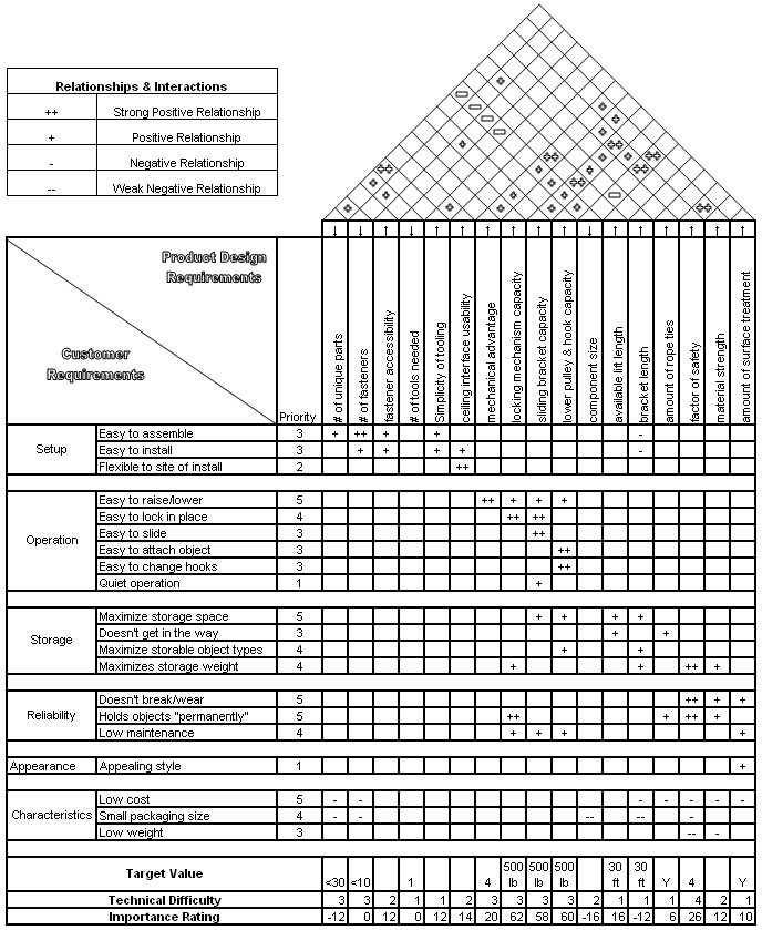
As we designed the ceiling-mounted storage lift, we set up a Quality Function Deployment (QFD) to give us quantifiable engineering targets to strive for. We met, or came acceptably close to most of our goals such as having less than thirty parts and having a maximum load of 480 pounds. By meeting these goals, we feel that our product has an advantage over the ceiling-mounted bicycle lift and similar products on the market. Our product is attractive to many more buyers and is more useful to each of those individual customers. It is rated to carry a heavier load and is adjustable to carry many different items. Other products on the market do not have the capability of easily adjusting the length between the brackets. Thus, their products limit the types of items one can store once the product is installed. The ceiling-mounted storage lift is especially attractive to buyers who will use the product to store seasonal items. The adjustable length between brackets and interchangeable hooks allow users to store different size and shape items at different times of the year using the same lift system. For example, a user is capable of storing a kayak during the winter months and store a rack of winter closing in the same location during the summer months when the kayak is in use. These features combined with the accomplished goals in our QFD give our product an edge over the competition.
- Please refer to the QFD page for a more detailed description of this design tool.
Final Prototype
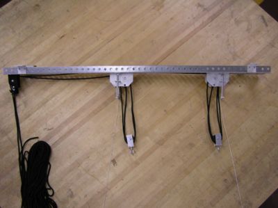
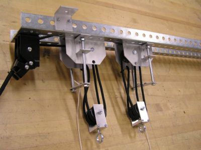
Our second prototype showed what we wanted to do very accurately but was unusable because many of the parts were not very strong or precise. We decided to start our final prototype from scratch and add parts from previous prototypes that we felt were up to the quality that we wanted. The rest of the parts were either bought or machined from aluminum. The parts that we reused from the second prototype were the locking mechanisms, string, hooks, and pulleys, which originally came from the ceiling mounted bike lift, as well as the L-brackets, and carabiners. The parts that we bought were the springs that were used in the lock for the upper brackets and all of the loading devices (the bin, clothes rack, etc.). Everything else we machined out of aluminum and put together ourselves. Building these parts, which consisted of the upper brackets, lower brackets, the u-bolt, and the mounting brackets, took a lot of time but ended up working much better than we originally expected.
The upper brackets were the most complex. The casing was made by first using the shearer to cut the sheet aluminum into the right shape. We then drilled holes for the axles, the U-bolt locks, and the bolts that held everything together. The axles, wheels, and spacers were made using a lathe.
The lower brackets were made almost the same way as the upper brackets. The casing was first made using the shearer. Holes were drilled into the casing to hold the axles and bolts. There was no U-bolt needed for the lower brackets. Then the axles and spacers were made using a lathe. No wheels were needed for the lower brackets.
The U-bolt was made as a square instead of a U. Basically we made a thin piece of metal with the band saw, drilled holes into the ends for screws, added springs to these screws and placed them on the upper bracket so that they were spring loaded.
The mounting brackets were very simple. They were made out of a bent piece of metal in which we drilled holes into so we could screw it into the wood.
The final prototype was fully functional, it just had a much lower loading capacity than our product will have. It demonstrates the pulley system, the movable brackets, the locking mechanisms, and the interchangeable lifting mechanisms very well. After the competition of the final prototype we learned that our strings can be very confusing and that we need to have different colored strings for the different parts that they move. Also, we learned that we needed longer strings for moving the brackets so that the ends of the strings don't get caught in the pulleys. The lock for the moving brackets was made out of three different parts in our prototypes and therefore would occasionally get caught on the L-brackets. In the design this part is made out of one U-bolt and will not have this problem.
User-Testing
Many of the users of our final prototype expressed very positive opinions of it. They were generally surprised with the ease of use and the wide range of items they could lift. One was actually so pleased with our design she offered to buy the actual prototype from us. Our test subjects were predominantly educated college students and were able to pick up on how to use the lift very easily, without any directions. Also, we found that they were able to change the end attachments quickly and without trouble. Our resources to test a wide range of users was somewhat limited, however during our exposition, we were able to get a couple of non-technical as well as non-college students to use the prototype. We found that these subjects did indeed have greater difficulty operating the prototype from pure intuition, but with brief verbal instructions they were able to quickly change this. We feel that adequate yet simple written instructions with parallel diagrams would yield these same results. A couple of minor problems that we found from our user testing are listed below in decreasing frequency of occurence:
1.) Confusion of which rope to pull in order to move the lift in different ways.
2.) Confusion of how to lock the lift at the top.
3.) Inability to lock the brackets in place after moving them.
4.) Tangling the sliding bracket ropes in the pulleys.
From this we were able to make several changes to eliminate these usability issues. We incorporated different colored ropes so that the user could effortlessly follow the path of the rope making the function of the rope essentially intuitive. Secondly we removed the threaded bolt from our sliding bracket locking mechanism. The window for proper function was significantly undersized, even for the experienced user. The tapered U-Rod allows for the lock to engage even if it's not perfectly aligned, and the absence of threading eliminates the catching experienced with the prototype. Lastly we found that making the sliding bracket ropes sufficiently long greatly reduced the oppurtunity for tangling in the pulleys.
Conclusion - Pursue for Production?
We believe that our design should be pursued for production. Our design opens the market of the lift from just bike users to all home owners. It does this at a very minimal cost(less than 10 dollars, for a total around 20-30 dollars), that most people said they would be willing to pay. The product may lose some of its appeal towards bike owners, but with the addition of a much larger market the gain should far out way the losses. The design is also safer than the bike lift in that it can hold more weight because of the dual locking mechanisms being used and is rated at a higher load capacity. The design also encourages many side products that can be offered. Designs of new lifting attachments and L-channel extensions can be produced and sold separately for extra flexibility in the product. Finally, after having several user testing subjects offer to buy our final prototype we know that the need for a product like this in the market is there.
Production Plan
The design is almost completely ready for production. Some cost/revenue research must be done first in order to minimize the cost to produce the product and maximize the revenue received. In order to minimize cost some parts may need to be exchanged for more economical parts that will do the same job. Some user testing on a prototype that completely represents what the product will look like and do will also be necessary. This user testing will have to have a much wider representation of the general population than previous user testing in order to find problems that may have been missed in the past. Market research on packaging also needs to be done. We need to find out whether to package multiple lifting mechanisms with the lift, increasing price of the lift, or to package them separately, lowering the price of the lift and allowing people to buy just the specific lifting mechanism that they want would be more advantageous. Obviously people would want to be able to buy just the lift and the lifting mechanisms that they want, but it may be more profitable to sell everything in the same package and forcing people to buy the lifting mechanisms that they do not need. After this final research is done and nothing comes up that would hinder production, the design will be ready to be produced.
Group Members: Jeff Polack, Kevin Pruzinsky, Davey Quinn, Russel Verbofsky
