Retractable extension cord
From DDL Wiki
Contents |
Executive Summary
Retractable cords are very practical for household purposes because their adjustable length allows users to use electrical appliances in any place they desire. In order to further understand the full functionality scope of retractable cords, our team analyzed and disassembled a Bayco 30 ft. retractable cord reel. In the preliminary stages of our study, we have identified the major stakeholders to be the manufacturer, customer, retailer, and distributor. The product reviews conveyed that customers generally use this product in garages for using power tools and other electrical hardware. The positive reviews show that most users feel satisfied with the length of the cord and its relatively cheap pricing while the negative reviews reveal some reliability and durability issues with the product.
During the product user study our team found the dispensing process of the cord from the casing to be a bit rough as we needed to put a little bit of force into pulling on the cord at times. Upon disassembling the product, we were able to analyze the mechanical and electrical components of the product. The main mechanical function of the product is advocated by a ratcheting mechanism that stops the rotation of the coil reel and by a condensed spring coil that applies a torsional force to retract the cord back into its casing. After careful examination of all the product components, we found that the majority of the parts were made of steel and plastic while only several of them were made of rubber and other metal alloys.
The design for environment analysis of the retractable cord shows that the highest Carbon dioxide emission in the product’s life cycle is caused by electricity usage and copper wire production. Reducing the amount of copper wire and electricity used may solve this problem, but it can also compromise some features of the product. We believe that there are other ways to improve the product for the environment without affecting the product features such as implementing online user manual and using less cardboard for packaging. Using the the Economic Input-Output Life Cycle Assessment (EIO-LCA) our team discovered that the calculated total electrical energy consumed by the device is 128 kWh for a lifetime of 10 years. Design for manufacturing and assembly assessment shows that the retractable cord has a lot of unique components. Using more standardized screws or fasteners for most of the inner components can improve manufacturing processed. For instance, replacing the melted plastic tabs for the rivets with snap fit tabs to minimize operation cost and procedure. Failure modes and effects analysis reveals that the most severe product failure comes from short circuiting the product, which can be caused by poor insulation of the electrical contacts. Deformation of some components such as the spring retainer and the coil reel is another failure mode to consider. These damages can cause product functionality failure, which possibly explains some of the reliability and durability issues we encountered in the product review.
After conducting an extensive product user study, carefully examining the disassembled components, and performing various design analysis on the product, our team believes that there are a lot of improvements that can be made to this product. We will carefully note these improvement ideas as we advance to the next step of our design process.
Major Stakeholder Analysis
Listed below are the major stakeholders for the retractable light, which include the manufacturer, customer, retailer, and distributor. The manufacturer generally would strive for low cost to mass produce the product for profit. The customer generally would need the product to be low cost, durable, and safe to use since they desire the product quality they pay for. The retailer would strive for low bulk pricing so that they can purchase the product in large quantity to sell to the customer. The distributor generally would need the product packaging to be durable and able to protect the product during the shipping process.
Manufacturer
- Low material costs
- Limited number of parts
- Ease to assemble
- Ability to be mass produced
- Environmentally friendly manufacturing processes
- Easy to package and ship
Customer
- Easy to use and install
- Multiple mounting options
- Low cost
- Durability
- Portable or light weight
- Ergonomic design
- Good aesthetics
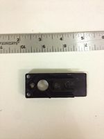
- Multiple length adjustment positions
- Waterproof
- Safe to use
- Ability to customize cord length and reel cover color
- Easy to repair or disassemble
Retailer
- Good aesthetics
- Small packaging size
- Good performance
- Low bulk pricing
Distributor
- Low weight
- Durable product packaging
- Space optimized packaging
- Packaging protects product
Product User Study
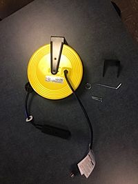
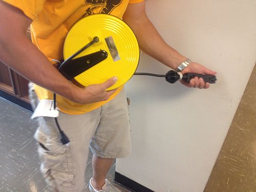
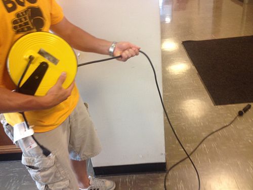
The Bayco Retractable Cord Reel utilizes a spring-loaded, rotational, ratcheting mechanism to provide the user with the functionality of a normal extension cord but with the added benefit of being able to easily retract and store the full length of the cord.
Installation and Daily Use
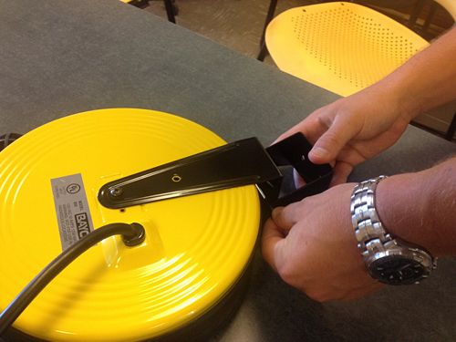
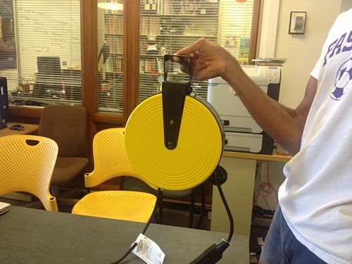
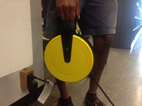
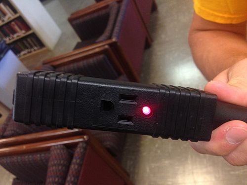
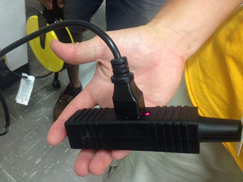
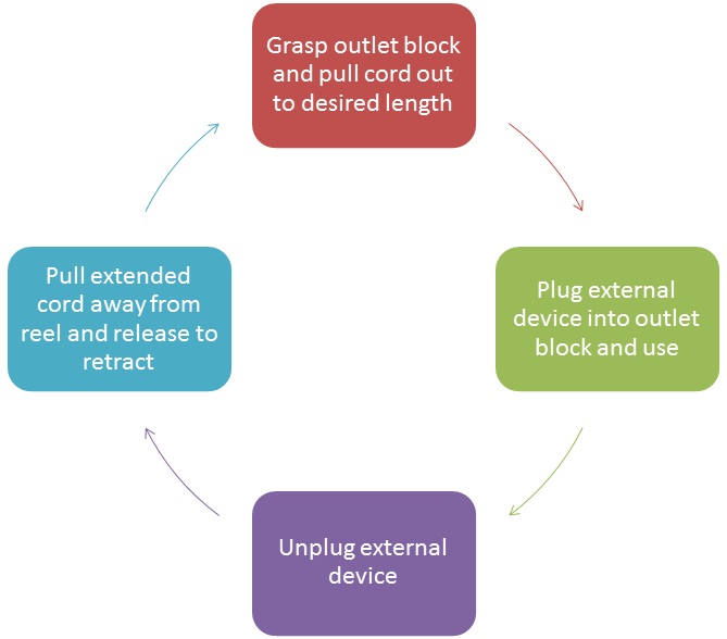
The user should mount the provided bracket to the ceiling or wall using the included hardware. Once mounted use the locking pin and ring to secure the cord reel to the bracket. After plugging the cord reel into a grounded 3-prong outlet the LED power indicator on the outlet block will light up, indicating the reel is ready for use. An included spherical rubber stopper on the extendable cord can be moved by the user to change the length of cord which is not retracted into the reel. The user should continuously pull on the outlet block to the desired length. The user can then plug in their electrical devices into the outlet block. When use is complete the user should unplug their external devices and pull firmly on the outlet block until they feel the reel release and the cord is retracted.
Mechanical Function
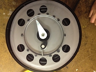
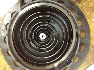
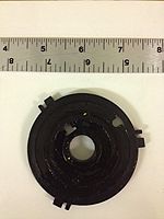
The cord reel contains a steel torsional spring which provides the force to retract the cord. A ratcheting mechanism allows the spool on which the cord is wrapped to lock in different rotational configurations. The ractheting mechanism consists of a spring-loaded pawl and gear. The gear is fabricated with teeth covering approximately two thirds of the circumference. The remaining one third of the circumference has no teeth and a small radius; this results in the pawl slipping on the teeth in only one direction, but when it is in the toothless region it has the ability to switch directions, i.e. allowing the cord to retract freely.
User Study
We determined the retractable cord reel to be ideal for the at home handyman. We have seen use of the retractable cord reel in an automotive garage as well as a machine shop. Users of the retractable cord reel should exhibit caution when mounting the product, particularly at high locations. Precautionary measures should be taken when operating in wet environments as the cord reel does not appear to be waterproof and utilizes electricity in its functionality.
We found it appealing that the installation and use of the cord reel was fairly straightforward. The cord reel appears to be fairly sturdy and the metal external housing was one thing that made us choose this particular reel over other brands. Dissection of the product was not simple but was achievable with a flat head screwdriver, a Philips head screwdriver, hammer, pliers and drill.
Some parts of the cord reel that we felt could be improved were the ratcheting mechanism, the opening of the casing through which the cord retracts, a more ergonomic outlet block, and the size of the cord reel. The current ratcheting mechanism has very specific positions at which the cord will actually retract. We felt that adding bristles to the cord retraction opening on the casing would be useful for keeping the inside of the casing clean from dirt that may become attached to the cord during use. A more ergonomic cord block would be beneficial for pulling the cord effectively during use. Finally we thought the size of the cord reel could potentially be reduced slightly.
Bill of Materials
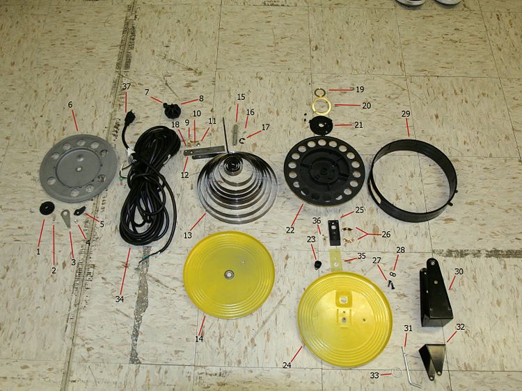
Upon completing the dissection of the product, 37 different components were found within the product. The majority of the materials were made of steel and plastic while a few were made of rubber and other metal alloys. The main parts of the product includes the ratcheting mechanism, the spring coil, the extension cord wrapped around the coil reel and the electrical components.
| Item Number | Description | Quantity | Mass (g) | Function | Material | Manufacturing Process | Image |
|---|---|---|---|---|---|---|---|
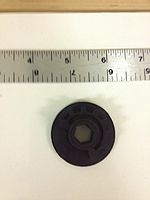
| 1 | Ratchet Gear | 1 | 7 | Stops the coil reel from rotating using its notches and allows the cord to retract using its concave edge | Plastic | Injection molded | |
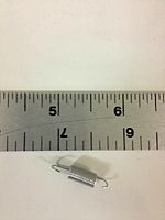
| 2 | Pawl Spring | 1 | <1 | Provides loading to keep the pawl intact to the ratchet gear | Stainless Steel | Extruded, bent & cut | |
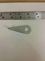
| 3 | Spring Position Retainer | 1 | 11 | Locks the spring mounting rod in place using the outer casing | Steel | Sheet stamped & bent | |
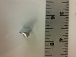
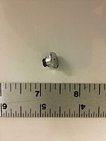
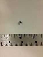
| 4 | Pawl Rivet | 1 | <1 | Fastens the pawl onto the metal coil flange | Aluminum | Extruded & cut | |
| 5 | Pawl | 1 | 2 | Slides into one of the ratchet gear notches to stop coil reel rotation and slides off to let the cord retract | Plastic | Injection molded | |
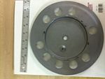
| 6 | Metal Coil Flange | 1 | 220 | Holds the main ratcheting mechanism that controls the coil reel rotation | Steel | Sheet stamped | |
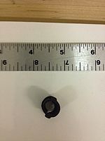
| 7 | Plastic Ball Insert | 1 | 1 | Locks the extension cord into the plastic ball | Plastic | Injection molded | |
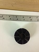
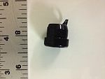
| 8 | Plastic Ball | 1 | 19 | Prevents the wall plug from getting retracted into the casing | Plastic | Injection molded | |
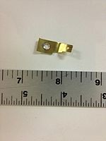
| 9 | Spring Electrical Contact | 1 | 1 | Conducts electricity through the spring coil | Copper | Sheet stamped & bent | |
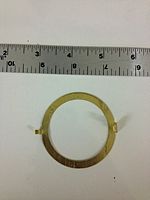
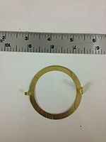
| 10 | Spring Electrical Contact Washer | 1 | 1 | Distributes the load provided by the spring electrical contact rivet | Steel | Sheet stamped & cut | |
| 11 | Spring Coil Rivet | 1 | 2 | Fastens the spring electrical contact and the outer end of the spring coil onto the spring reinforcement plate | Aluminum | Extruded & cut | |
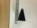
| 12 | Spring Reinforcement Plate | 1 | 10 | Holds the outer end of the spring coil while being attached to the coil reel | Steel | Stamped & cut | |
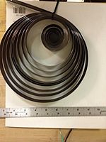
| 13 | Spring Coil | 1 | 516 | Applies torsional force to rotated the coil reel and retract the cord into the casing | Galvanized Steel | Stamped, cut & bent | |
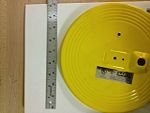
| 14 | Side Casing | 1 | 253 | Encloses the extension cord, spring coil, coil reel, and most components of the retractable cord | Steel | Sheet stamped & bent | |
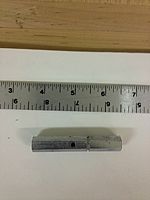
| 15 | Spring Mounting Rod | 1 | 50 | Prevents the inner end of the spring coil from turning while the coil is applying force to retract the cord | Steel | Extruded & cut | |
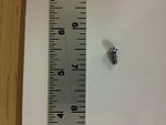
| 16 | Spring Mounting Rod Screw | 1 | <1 | Fastens the inner end of the spring coil onto the spring mounting rod | Steel | Purchased | |
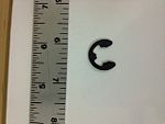
| 17 | Spring Mounting Rod Lock | 1 | <1 | Prevents the spring mounting rod from sliding around the center hole of the coil reel | Steel | Stamped & cut | |
| 18 | Spring Electrical Contact Rivet | 1 | 1 | Fastens the spring electrical contact onto the spring reinforcement plate | Aluminum | Extruded & cut | |
| 19 | Small Circular Electrical Contact | 1 | 2 | Conducts electricity from the copper wires | Copper | Sheet stamped & bent | |
| 20 | Large Circular Electrical Contact | 1 | 3 | Conducts electricity from the copper wires | Copper | Sheet stamped & bent | |
| 21 | Circular Electrical Contact Casing | 1 | 11 | Holds both circular electrical contacts and locks the copper wires onto the coil reel | Plastic | Injection molded | |
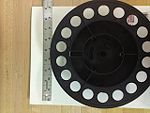
| 22 | Coil Reel | 1 | 161 | Rotates to dispense the cord and provides space for the cord to wrap around | Plastic | Injection molded | |
| 23 | Electrical Wire Casing | 1 | <1 | Holds the copper wires through the coil reel | Plastic | Injection molded | |
| 24 | Side Casing with Plug | 1 | 255 | Encloses most components of the retractable cord and holds the cord end with the wall plug | Steel | Sheet stamped & bent | |
| 25 | Fixed Electrical Contact Casing | 1 | 6 | Holds the fixed electrical contacts | Plastic | Injection molded | |
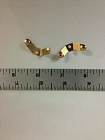
| 26 | Fixed Electrical Contacts | 2 | 0.5 | Conducts electricity from the copper wires | Copper | Sheet stamped & bent | |
| 27-28 | External Clamp Hardware | 4 | 4 | Attaches the external clamp to the side casings | Steel | Purchased | |
| 29 | External Plastic Casing | 1 | 135 | Encloses most components of the retractable cord and lets the cord out of the casing | Plastic | Injection molded | |
| 30 | External Clamp | 1 | 173 | Holds the external casings together and locks them to the mounting bracket | Steel | Sheet stamped & bent | |
| 31 | Mounting Bracket Pin | 1 | 16 | Locks the external clamp to the mounting bracket | Stainless Steel | Extruded & bent | |
| 32 | Mounting Bracket | 1 | 105 | Allows retractable cord to be permanently mounted to a ceiling or wall for easier use | Steel | Sheet stamped & bent | |
| 33 | Pin Locking Ring | 1 | 1 | Holds mounting bracket pin in place | Stainless Steel | Extruded & bent | |
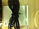
| 34 | Extension Cord | 1 | 1084 | Allows flexible use of electrical hardware within the household | Copper wires & rubber casing | Purchased | |
| 35 | Insulating Sheet | 1 | 1 | Prevents the fixed electrical contacts from touching the metal side casing | Silicone | Purchased | |
| 36 | Fixed Electrical Contact Rivets | 3 | <1 | Fastens the fixed electrical contacts onto the rectangular plastic casing | Copper | Extruded & cut | |
| 37 | Wall Plug | 1 | 85 | Connects the extension cord to electric sockets | Copper & rubber casing | Purchased |
Failure Mode and Effects Analysis (FMEA)
Failure mode and effect analysis, or FMEA, is a guideline to evaluate potential issues regarding a product. FMEA takes into account different parts and functions of a product, the effects of failure from each component and ways to remedie the potential failures. FMEA also quatifies risk by assigning a value to the severity (S), occurrence (O), and detection (D) of the failure, to determine the failure's risk priority number (RPN). By separating and analyzing the different components of the retractable power reel, several failure modes were found as shown in the following table.
From the analysis we concluded that the cord reel is a safe product on its own. The most severe occur during user misgauge such as when water contacts the outlet. However, since the main use for such a product is in a dry environment, chances of such failure to occur are slim. The table instead reveals that the potential of the reel falling from its mount has the highest risk priority number. This is attributed to the weight of the reel, the varying mounting surfaces and the varying pulling forces applied which pose considerable amounts of stress to the screws and surface mounting the reel.
| Item and Function | Failure Mode | Effects of Failure | S | Causes of Failure | O | Design Controls | D | RPN | Recommended Actions |
|---|---|---|---|---|---|---|---|---|---|
| Wiring/Ground | Damage | Short circuit/electric conduction to outer shell | 9 | Physical shock (i.e. fall) | 2 | Silicon insulating tab | 9 | 162 | Additional methods to restrain to ground end |
| Power Cable | Fatigue | Cord unable to reel back | 4 | Over pulling (User) | 4 | Limited length of cord | 3 | 48 | Warning mark when approaching limit |
| Outlet | Water damage | Outlet becomes unusable/electric hazard | 8 | Water/liquid (User) | 3 | N/A | 5 | 120 | Warning sticker discouraging usage near water |
| Wall Mount | Strain | Assembly can fall from mounted location | 6 | Poor adherence to mounted area (User) | 5 | N/A | 7 | 210 | Warning sticker with mounting guides |
| Plastic Cover | Melting damage | Complicate reeling, cause poor appearance and odor | 4 | Excessive heat | 3 | N/A | 2 | 24 | Sticker with limits of operation temperatures |
| Central Pin Retainer | Deformation | Cause reel to disassemble | 7 | Fatigue | 4 | N/A | 6 | 168 | 1/100,000 Fatigue tests |
| Ratchet Spring | Fatigue | Cord unable to reel back | 4 | Loosing or fracture | 4 | N/A | 7 | 112 | 1/100,000 Fatigue tests |
Design For Environment (DFE)
When examining a product, it is important to consider Design for Environment (DFE). Based on our DFE study on this product we are prepared to make the following recommendations to make the product more environmentally friendly:
- Instead of a paper instruction manual one could be provided for the user online. This will lower the amount of GHGs that would be produced in the paper making process.
- The cardboard packaging is not needed. Simply providing some type of hook on the product will allow for it to be hung in the store making the cardboard box obsolete.
- Removal of the LED indicator light will lower the lifetime energy usage of the product by not continuously drawing power.
The use of the product, manufacture of the product, and extraction of raw materials needed to make the product all produce greenhouse gases such as carbon dioxide (CO2). The CO2 production associated with each component of a product life cycle can be analyzed in order to determine the component that produces the most CO2. Then, the product can be redesigned in order to reduce the CO2 production associated with that particular life cycle component. This will result in a more environmentally friendly product that produces less greenhouse gases over its lifetime. Reduction of greenhouse gases will become particularly important if Congress passes a law that fines companies $30 for each metric ton of CO2 that it produces.
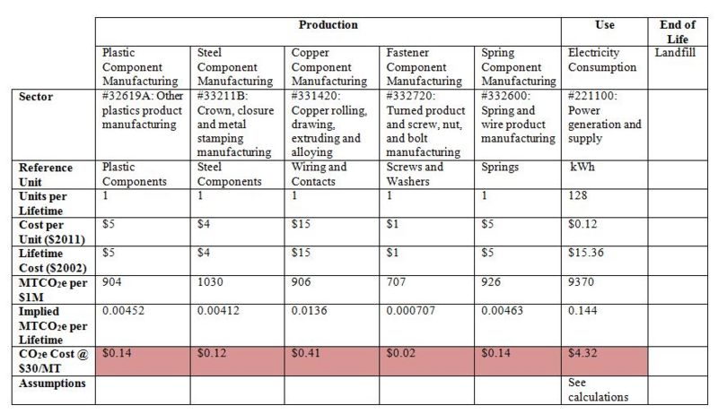
The production aspect of the product life cycle was divided into 5 distinct areas--plastic production, copper drawing, steel stamping, spring manufacture, and fastener production. Almost all of the product's parts fall under one of these 5 categories. The total cost of the product ($30) was divided amongst these 5 material categories based on the amount and cost of each material contained in the product. Copper drawing accounts for half ($15) of the total product cost due to the high price of copper and because the extension cord, which is primarily composed of copper wire, is the main component in the product. Fastener production only accounts for $1 of the total cost because there are only a few small fasteners used in the product. The remaining product cost ($16) is almost evenly divided amongst plastic production, steel stamping, and spring manufacture. Although there is a high number of plastic parts, plastic is a cheaper material than steel, making their respective prices almost equal. The spring manufacture cost ($5) accounts for the large size of the spring and the heat treating needed to make it. The only CO2 producing component of use associated with this product is the electrical energy consumed by the power indicator LED and lost due to resistance in the cord. This electrical energy is calculated using the below procedure.
First, the energy lost due to the LED is calculated. It is assumed that the LED consumes 1 W (0.001 kW) of power. This LED is always on when the extension cord reel is plugged into an outlet. Also, the assumption is made that the cord reel is always plugged in so the LED will be on for the 10 year lifetime of the cord reel. The total energy, ELED, consumed by the LED is calculated below:
Next, the energy lost due to the resistance of the cord is calculated. The extension cord is made from 16 gauge wire, which has a resistance of 4.08 Ω per 1000’ of wire (Lucius). First find resistance, Rcord, of the 30’ cord:
Assume that the extension cord is being used to power both a ½” drill and a portable grinder. The ½” drill uses 750 W of power, Pdrill, while the grinder uses 1380 W of power, Pgrinder ("How Many Watts Do You Need"). Assume that the two devices are used equally so the average power, Paverage, used is:
Next, find average resistance produced by the devices being powered. Assume that the household outlet the reel is plugged into provides a voltage, V, of 110 V:
The current, I, in the system is:
Calculate voltage drop, Vloss, across extension cord:
Calculate power loss, Ploss, due to extension cord:
Assume that tools are powered from the extension cord on an average of 1 hour each day over the 10 year lifetime of the cord reel. Find total amount of energy, Ecord, consumed by the cord due to lost power:
Thus, the total electrical energy, Etotal, consumed by the device is calculated below:
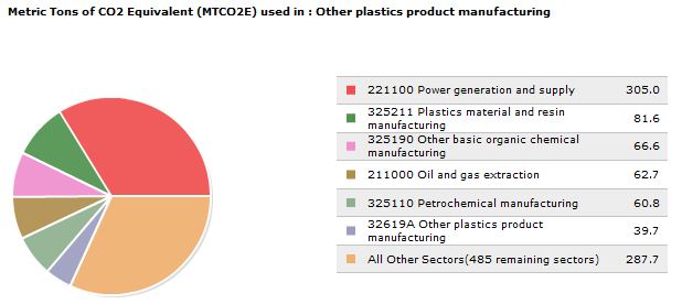
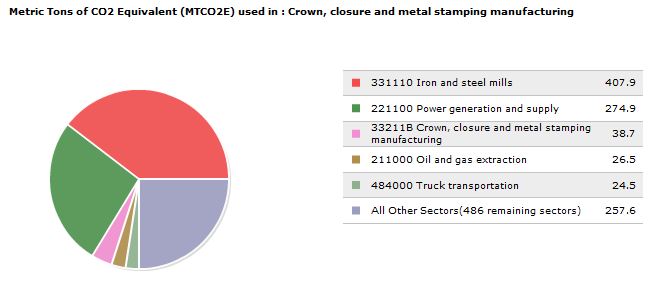
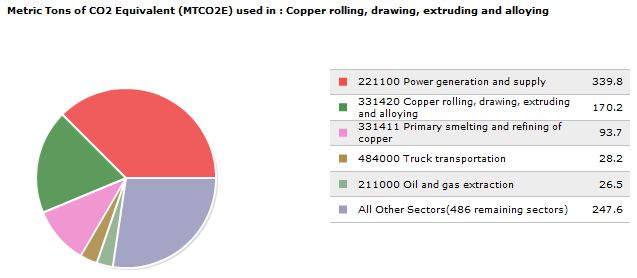
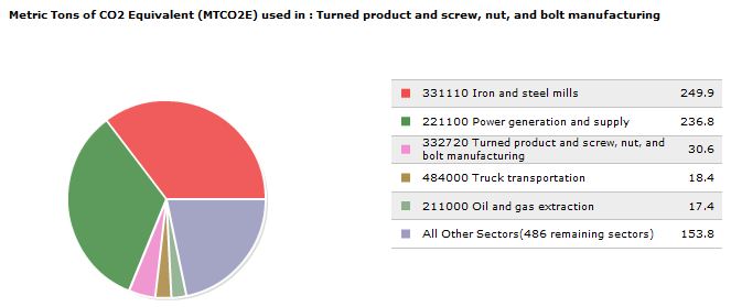
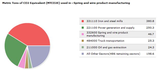
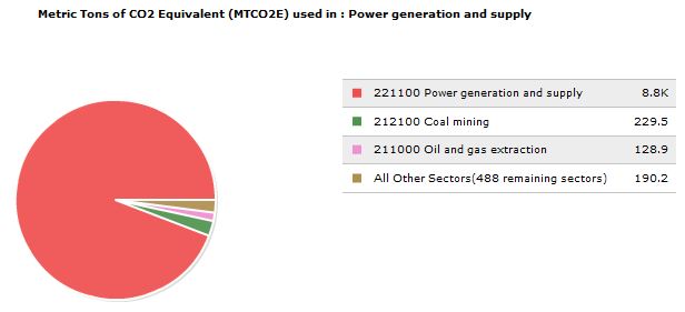
The information presented above was used in conjunction with the Economic Input-Output Life Cycle Assessment (EIO-LCA) to find the total amount of CO2 produced by each component of the product's life cycle. These values are presented in the below table and pie charts. The electricity cost comes from the National Public Radio (NPR) website and is the average US electricity cost for 2011.
As can be observed in the above table, the greatest sources of CO2 production during this product's life cycle are due to electricity use and copper wire production. So, the elimination of the power indicator light and a reduction in the length of the cord represent two ways CO2 production could be reduced during this product's life. However, both of these options would potentially result in a product that is less attractive to the consumer.
The table below summarizes aspects of the product that are already environmentally friendly and identifies ways the product could be changed to render it more environmentally friendly.
| DFE Guideline | Good Aspects of Competitor Product | Ideas for Improvement |
|---|---|---|
New Concept Development
|
|
|
Select Low Impact Materials
|
|
|
Reduce Material Amount
|
|
|
Eco-Manufacturing
|
|
|
Optimize Distribution
|
|
|
Reduce Use-Phase Impact
|
|
|
Maximize the First Life
|
|
|
End of Life
|
|
|
Design For Manufacturing and Assembly (DFMA)
In general, some goals for designing for manufacturing and assembly are: ease of manufacturing and assembly, lower production cost with maintenance of high quality products. These goals can be attained among other ways by making informed decisions in design of part features and in choosing particular classes of manufacturing process, i.e. casting and molding, deformation, subtractive processes, and joining.
The Bayco Cord Reel that we are analyzing made use of the following processes in manufacturing:
- Injection molding for plastic parts
- Deformation:
- Stamping of sheet metal
- Melting of plastic to form joints
- Rolling of steel to form a torsional spring
- Subtractive machining of spring mounting rod for snap ring
The table below lists some specific guidelines that should be followed in manufacturing and assembly as well as how we saw them implemented in the competitor's product and areas that we felt could use improvement.
| DFMA Guideline | Good Aspects of Competitor Product | Ideas for Improvement |
|---|---|---|
Minimize Part Count
|
|
|
Standardize Components
|
|
|
Commonize Product Line
|
|
|
Standardize Design Features
|
|
|
Keep Designs Simple
|
|
|
| Multifunctional Parts |
|
|
Ease of Fabrication
|
|
|
Avoid Tight Tolerances
|
|
|
Minimize Secondary & Finishing Operations
|
|
|
| Take Advantage of Special Process Properties |
|
|
Minimize Assembly Surfaces
|
|
|
Use Subassemblies
|
|
|
Mistake-Proof
|
|
|
Minimize Fasteners
|
|
|
Minimize Handling
|
|
|
Minimize Assembly Direction
|
|
|
Provide Unobstructed Access
|
|
|
Maximize Assembly Compliance
|
|
|
Other
|
|
|
Having analyzed the information in the table we concluded that from a manufacturing and assembly standpoint the competitor's product is already fairly simple, but it could be further improved in the following ways:
- Designing electronics in a way that they can be either sub-assembled and included in a bottom-up assembly process, or redesign their housing in the current design to accommodate a bottom-up assembly to a greater extent
- From what we could tell, apart from the placement of the electrical conducts and wires the assembly of this product can be conducted in a bottom-up fashion
- Instead of using melted plastic tabs, a particularly irreversible process in the sense that the tabs can not be reused after being melted once, use a snap fit type of design.
- The use of melted plastic tabs to join two parts together was novel to us - to clarify, small plastic tabs were designed as part of the plastic coil reel. These tabs were then inserted into metal slots of the metal coil flange, melted and pressed down to form a fixed joint
- We felt that this method of joining was not very useful in the case of having to repair a component contained within the plastic-metal coil reel structure
- Furthermore if the tabs are melted without proper alignment first, the whole plastic coil reel cannot be reused and possibly the metal coil flange depending on whether taking the time to clean melted plastic off of it is cost effective
The competitor's product was well designed for manufacturing and assembly in that it:
- Used minimal secondary operations, such as painting
- Made use of high production volume manufacturing processes, such as injection molding
- Had few extraneous parts or features
- Used materials fairly easy to work with
- For the most part used a bottom-up assembly process
Team Roles
The team member and their role for Phase 1 was:
Team Leader: Brandon Girmus
DFMA Lead: Harsha Alles
FMEA Lead: Jonathon Monthe-Siewe
DFE Lead: Joe Barbish
Executive Summary & Bill of Materials: Albert Yoewono
Our team met on a weekly basis to discuss our progress on each of our assignments. In these meetings we collaborated with one another to complete these sections. Cooperation and communication played key roles in our group's success.
References
Economic Input Output Life Cycle Assessment (EIO-LCA). US 2002 Industry Benchmark model. Carnegie Mellon University Green Design Institute, 2008. Web. 20 Sept. 2012. <http://www.eiolca.net/>
"How Many Watts Do You Need?". DonRowe.com, 2012. Web. 22 Sept. 2012. <http://www.donrowe.com/inverters/usage_chart.html>
Jiang, Jess. "The Price Of Electricity In Your State." NPR, 28 Oct. 2011. Web. 20 Sept. 2012. <http://www.npr.org/blogs/money/2011/10/27/141766341/the-price-of-electricity-in-your-state>
Lucius, Jeff. "Wire Resistance and Voltage Drop Calculator." Stealth 316, 22 July 2012. Web. 22 Sept. 2012. <http://www.stealth316.com/2-wire-resistance.htm>
