Retractable umbrella
From DDL Wiki
Contents |
Executive Summary
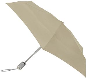
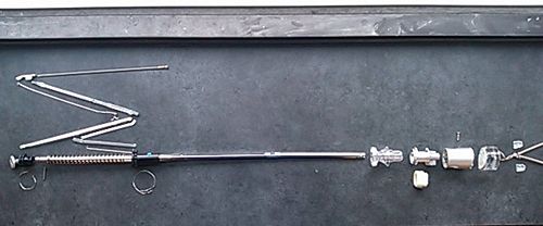
An umbrella is an external accessory that is commonly used by individuals to prevent exposure to weather elements such as sunlight, rain, and snow. Many contemporary umbrellas come with telescoping frames that house an expansion spring and are attached to a second spring via the rider. The springs aid with the compression and the automation of the umbrella’s expansion while structural arms attached to the telescoping frame via the rider help strengthen the over- arching canopy. They also help decrease the force the user must input in order to close the umbrella. During this phase we dissected a competitor’s umbrella (specifically a Totes collapsible umbrella) to identify the components of the product, the mechanisms at work during the expansion and contraction of the umbrella, and to understand the intricacy of its design.
From our dissection study we determined that the umbrella is a complex work of engineering. The competitor’s product incorporates components that ease the manufacturing process. Some these components include stamped links, standardized rivets, multipurpose parts, and materials that are easy to work with (i.e. aluminum and plastic). However it’s use of numerous subassemblies complicate the assembly process and leaves room for improvement of the design. To improve the ease of assembly we recommend consolidating the entire skeletal structure of the umbrella cover into one flexible component; increasing the function of multiple components so as to remove single purpose components, removing the polished portion of the umbrella handle, which seems to serve no purpose, and replacing it with a material that would complete the handle and add another function to it. We also suggest incorporating snap-fits into the umbrella design to eliminate rivets and other fasteners that can be replaced.
Major Stakeholders and Their Needs
Four major stakeholders were identified in the life cycle of the umbrella: the consumer, the retailer, the manufacturer and the distributor. The following table summarizes the needs and desires of each stakeholder. Each of them is described in detail in the following subsections.
| Stakeholder | Needs | Desires |
|---|---|---|
| Consumers |
|
|
| Retailers |
|
|
| Manufacturer |
|
|
| Distributors |
|
|
Consumer
An umbrella is a product commonly used by people to refuge from rain and other environmental phenomena. Most people have had at least one umbrella in their lifetime, therefore consumer diversity was considered during the evaluation of their needs. The requirements of the consumer can be summarized as:
- Rigidity: the product needs to be able to support itself in the hands of the person using it.
- Portability: consumers want a product that they can carry around all day, they need a product that is compact and easy to carry.
- Appearance: the products should appeal the consumer.
- Low cost: as a product that users carry all day, umbrellas tend to be lost or forgotten often. A low cost device could be replaced more often than an expensive one. In addition, many consumers would not want to spend a large amount of money in a commonly used object.
- Safety: umbrellas have many small components and outstanding elements, they need to be safe for people to use.
- Durability: consumers want a product that does not need replacement often.
- Light-weight: commonly, consumers carry umbrellas all day with them, most would opt not to carry or use it if it is too heavy.
Retailer
The fact that umbrellas are commonly used object makes their market a competitive one. Retailers needs are focused on making their product profitable. The following list summarizes their needs:
- Appearance: the product needs to be appealing to the consumer in order to be competitive.
- Price: the product needs to have a reasonable price that will yield revenue.
- Reliability: the product needs to be reliable, since its reputation reflects on the name of the retailer.
- Safety: the product needs to be safe, since the retailer is responsible for accidents that an error in the product could cause.
Manufacturer
Manufacturers want to minimize the cost and time of manufacturing processes. The following list summarizes their needs:
- Simplicity of the design: manufacturers need a simple design with simple geometries.
- Modularity of the design: manufacturers need a modular design that optimizes the processes of manufacture.
- Materials: low cost and non-toxic materials minimize the cost of the manufacture.
- Manufacturing process: fast and low cost processes optimize the price of the manufacture.
- Safety: safe manufacturing procedures are required by the manufacturers in order to minimize employee accidents at work.
- Storage: minimum the weight and overall dimensions make the object easier to store and transport.
Distributor
Distributors want to minimize the cost and time of transportation and distribution of the product. The following list summarizes their needs:
- Compact: the product needs to be easy to pack, and able to survive storage and distribution
- Modularity: the product needs to have modular replacement parts
- Storage: minimum the weight and overall dimensions make the object easier to store and transport.
Product History
The use of the collapsible umbrella dates back to the 1st century A.D. According to wikipedia, “the oldest reference to a collapsible umbrella dates to the year 21 A.D.” (4) The collapsible umbrella is said to have been designed in China “for a ceremonial four-wheeled carriage” under the rule of Wang Mang. Over the years the collapsible umbrella received significant redesigns, each of which helped create the common design present in contemporary collapsible umbrellas. One notable redesign was the incorporation of a telescoping frame, credited to Hans Haupt of Berlin (5). Haupt’s initial purpose for the telescoping umbrella was to have it function as a cane and an umbrella. The telescoping frame allowed him to carry both around at a size that fit into his pocket. Another notable redesign was the incorporation of new materials such as cotton, plastic film, and nylon to replace original silk.
Product Functionality and Use
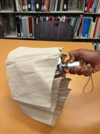
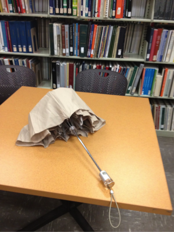
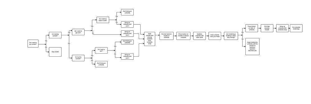
To open the umbrella, the user presses the button on the handle and allows it to extend and then expand fully. Then he or she holds the umbrella over her or his head to prevent rain or sun from reaching her or him. To close the umbrella, the user pushes the button on the rider to free it and then pulls it down until it is locked back into the handle. Figure 2 shows the umbrella in closed form, whereas Figure 3 shows the umbrella in opened form. Below those two figures is a flowchart that demonstrates the decision processes involved in choosing whether to use an umbrella or not. Also, the flowchart includes the actions and procedure required to open and close an umbrella. The exact mechanisms in the umbrella are described in further detail in the Mechanical Function section.
Mechanical Function
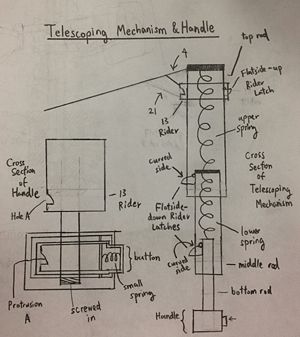
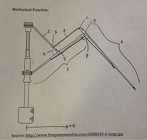
When a retractable umbrella opens, two things happen mechanically: (1) it extend vertically away from the handle and (2) its eight arms expand outward to stretch the polyester cloth and protect the user from the elements. The exact opposite happens when the umbrella is closed. In the descriptions below, specialized terms (shown in italics) are used. Refer to Figures 5 and 6 for illustrations of to what these terms are referring.
Opening the Umbrella:
To open the umbrella, the user presses the release button. This causes protrusion A, located in the rear of the release button, to move out of Hole A, located on the rider. The rider is then free to move away from the base. The rider moves upward, away from the base because it is attached to the top rod (Figure 5). The top rod is attached to the upper spring, which is attached to the middle rod. The middle rod is attached to the lower spring, which is attached to the bottom rod. As a result, the rider springs upwards away from the handle. Because the springs and rods are all interconnected, the whole telescoping mechanism also springs into its full length. During this, the flatside-down rider latches spring out to secure the telescoping mechanism and prevent it from recompression. The flatside-up rider latch also springs out. However, this latch prevents the rider from leaving its final position.
The extension of the telescoping mechanism initiates the the umbrella arm mechanism (Figure 6). As the rider approaches its terminal position near the top of the rod, it pinches the ends of links 1 and 2 close, decreasing angle α. This causes the first four-bar linkage to pivot about pins A, B, C and D and straighten out. The slant of the first four-bar linkages cause the subsequent one to slant and straighten as well. A long rib attached to the end of the second four-bar linkage provides extra length to the umbrella arm.
An alternative way of explaining the mechanism is as follows:
- The rider moves upward, causing angle α to decrease, which in turn causes four-bar linkage ABCD to collapse. The decrease in angle α coupled with the collapse in the four-bar linkage simultaneously straightens and extends the arm outward.
- The combined effort of all the arms extending radially outward from the telescoping rod causes the umbrella to open.
It is important to note that, depending on the manufacturer, different umbrellas have slight variations in the design of the arm mechanism. The arm mechanism found in the dissected Totes umbrella is composed of two four-bar linkages in series. Figure 6 illustrates one such four-bar linkage. The function of the additional four-bar linkage used in the Totes umbrella is to increase the length of the arm while maintaining a compact frame (i.e: more folds, more compact).
Closing the Umbrella:
When closing up, the user needs to push in the flatside-up rider latch to free the rider from being secured. Then user then needs to pull the rider towards the handle. This will require force since the user is going against the compressive force of the spring. As the umbrella moves down the three rods of the telescoping mechanism, it engages with the curved side of the flatside-down rider latches. This pushes the flatside-down rider latches inward and frees the rods of the telescoping mechanism. This allows the umbrella to be retracted. When the rider moves down into the handle, it locks with protrusion A and remains there in the closed state. On the other hand, the umbrella arm mechanism does the same thing as it does when opening the umbrella except it is in reverse.
Bill of Materials
Assembly List
Parts List
| Part Number | Name | Quantity | Mass, g | Function | Material | Manufacturing Process | Image |
|---|---|---|---|---|---|---|---|
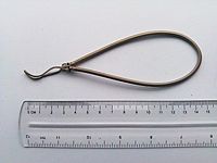
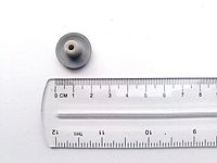
| 01 | Elastic Rope | 1 | 3 | Provides a convenient mode of carrying the umbrella when not in use | Rubber + Polyester | Cut from source rope and tied into loop shape | |
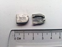
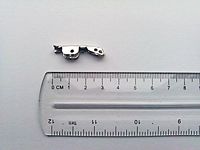
| 02 | Rope Clip | 1 | < 1 | Clips over tied end of elastic rope handle (part #01) to prevent fraying. Also the sight of brand logo | Plastic | Injection Molding | |
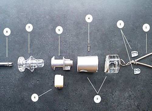
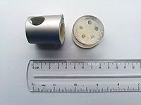
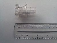
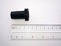
| 03 | Handle Mechanism Casing | 1 | 38 | To house release mechanism. Added weight and rigidity of clear cylindrical block enhances stability and strength | Plastic | Injection Molding | |
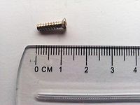
| 04 | Screw | 1 | < 1 | Attaches handle casing (03) to the anchor (05) and to the telescoping rod (08) | Steel | Subtraction & Deformation | |
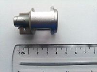
| 05 | Anchor | 1 | 4 | Houses release button (06) and handle spring (25). The rod of the umbrella (08) fits into a slot at the bottom of this part. A small notch at the top of this component keeps the release button (06) and rider (07) in proper alignment. A hole near bottom of component is location where the screw (04) attaches this component to the handle mechanism casing (03) and also to the rod. | Plastic | Injection Molding | |
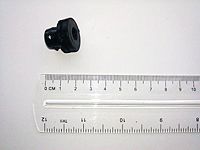
| 06 | Release Button | 1 | 4 | Releases latch inside handle to allow rod extension | Plastic | Injection Molding | |
| 07 | Rider | 1 | 11 | Once pushed upward by user, activates arm mechanism. Also locks umbrella in closed position when not in use | Acrylic | Injection Molding | |
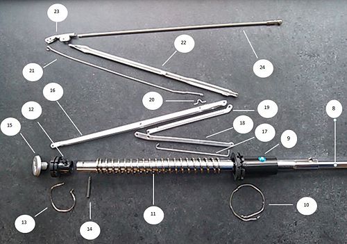
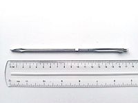
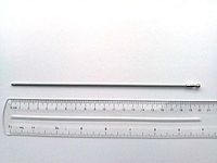
| 08 | Telescoping Rod and Spring | 1 | 46 | Holds the umbrella in place. A spring inside this set of concentric tubes allows umbrella to expand and contract. | Steel | [Insert Manufacturing process] | |
| 09 | Supporting Rider | 1 | 4 | Serves as an additional location to anchor struts (08) (instead of fastening them to the rider along with component 17. | Plastic | Injection Molding | |
| 10 | Supporting Ring 1 | 2 | <1 | Fastens struts (18) to supporting rider (09). Fastens wire connector A to rider (08) | Aluminum | Metal Deformation | |
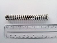
| 11 | External Upper Spring | 1 | 20 | Adds elastic potential energy to compress and release the umbrella. It allows it to contract and expand. | Steel | Deformation | |
| 12 | Top Notch | 1 | 3 | With the help of supporting ring 2 (13), attaches vane A (16) to the top of the telescoping rod (08) | Plastic | Injection Molding | |
| 13 | Supporting Ring 2 | 1 | <1 | Fastens Vane A (18) to the top notch (12). | Aluminum | Metal Deformation | |
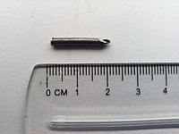
| 14 | Pin | 1 | <1 | Attaches top notch (12) to top of telescoping rod (08) | Steel | Subtraction | |
| 15 | End Cap | 1 | <1 | Seals top end of telescoping rod. Also serves as site of brand logo. | Plastic | Injection Molding | |
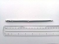
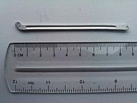
| 16 | Vane A | 8 | <1 | Connects top notch (12) to (22). Acts as part of the first four-bar linkage | Aluminum | Stamping & Deformation | |
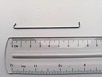
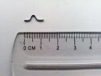
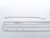
| 17 | Wire Connector A | 8 | <1 | Joins the rider (07) to the strut (18) | Aluminum | Deformation | |
| 18 | Strut | 8 | <1 | Connects supporting rider to vain. Acts as part of the first four-bar linkage | Aluminum | Stamping & Deformation | |
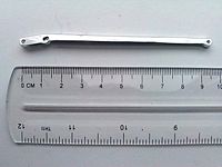
| 19 | Link | 8 | <1 | Acts as part of the first four-bar linkage. | Aluminum | Stamping & Deformation | |
| 20 | Linking Staple | 8 | <1 | Provides a platform for connecting wire 434523423 to link 435342664 | Aluminum | Deformation | |
| 21 | Wire Connector B | 8 | <1 | Part of second four-bar linkage | Aluminum | Deformation | |
| 22 | Vane B | 8 | <1 | Acts as second four-bar linkage | Aluminum | Stamping & Deformation | |
| 23 | Butterfly Connector | 8 | <1 | Joins wire connector B (21), Vane B (22), and rib (24). Acts as part of second four-bar linkage. The cloth (26) is attached to this component via string | Aluminum | Stamping & Deformation | |
| 24 | Rib | 8 | <1 | Provides additional length for the canopy arm. The cloth (26) is attaches to this component via string | Plastic | Injection Molding | |
| 25 | Internal Spring | 1 | 4 | Forces telescoping rod (08) upward when release button (06) is pressed | Steel | Deformation | |
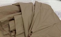
| 26 | Cloth | 1 | 60 | Shields user from the elements | Polyester | Sewing |
Analysis
The umbrella was analyzed following the guidelines taught in class. The following sections contain detailed analysis of the manufacture, the assembly, environmental impact and the failure modes of the umbrella.
Detailed Product Analysis
Design for Manufacturing & Assembly (DFMA)
The manufacturing and assembly practices used in the umbrella were analyzed in order to learn about the design. Each analysis is discussed in detail bellow.
Manufacturing
Overall the umbrella design used good manufacturing processes. Being a product invented centuries ago, its design has been improved over time, but it still has some areas of improvement. Some good design practices used in the design include the use of standardized fasteners through most of the components, the simplicity of the design of individual components and the use of stamped components through the design. Some improvements suggested include the use of one continuous arm that flexes into the desired shapes and the use of snap-fit links instead of links attached via rivets. The following table summarizes the good design practices and areas of improvement for the guidelines provided in class.
| Guideline | Good Design Choices | Areas for Improvement |
|---|---|---|
| Minimize Part Count: Eliminate fasteners, part consolidation |
|
|
| Standardize Components: Take advantage of economies of scale & known component properties |
|
|
| Commonize Product Line: Economies of scale and minimum training and equipment |
|
|
| Standardize Design Features: Common dimensions for fewer tools and setups | None
|
|
| Keep Designs Simple: simplest way to achieve needed functionality |
|
|
| Multifunctional Parts: |
|
|
| Ease of Fabrication: Choose materials easy to work with |
|
|
| Avoid Tight Tolerances: Causes exponential cost increases |
|
|
| Minimize Secondary & Finishing: Only where needed |
|
|
| Taking Advantage of Special Process Properties: | None
|
|
Assembly
Overall the umbrella design used extensive assembly practices. The umbrella dissection was complicated due to the vast amount of parts found in the design. The assembly of the umbrella seemed intuitive. Some good assembly practices include the use of many sub-assemblies to speed the assembly line and that the full assembly was consistent from top to end, all sub-assemblies can be added to the final assembly through the telescoping rod. Some improvements suggested include the use of component specific dimensions and the use of directionality driven components. The following table summarizes the good design assembly practices and areas of improvement for the guidelines provided in class.
| Guideline | Good Design Choices | Areas for Improvement |
|---|---|---|
| Minimize Part Count: Eliminate unnecessary parts | None
|
|
| Minimize Assembly Surfaces: and sequence them | None
|
|
| Use Subassemblies: Can be assembled and tested separately, can be outsource |
| None
|
| Mistake-proof: unambiguous, unique assembly orientation |
|
|
| Minimize Fasteners: snap fits and part consolidation | None
|
|
| Minimize Handling: Position for insertion or joining is easy to achieve |
|
|
| Minimize Assembly Direction: ideal is to add each component from top to base |
|
|
| Provide Unobstructed Access: Consider assembly path |
|
|
| Maximize Assembly Compliance: chamfers and radii help assemble parts with variance |
|
|
| Features that have no functionality but support assembly: |
|
|
Failure Mode Effects and Analysis (FMEA)
The two main issues that need to be dealt with in FMEA are:
- Plasticity of the rib and the umbrella arms (stretchers):
Wind and other external factors cause the umbrella to change shape or flips over. It’s important that a proper load analysis is done so that the 4-link joints that make up the stretcher as well as the arms that make up the rib of the umbrella have room for deformation before the umbrella gives in.
- Fabric Quality:
The quality of the cloth used must be checked and undergo quality assurance before it is manufactured along with the other parts. It is important that the right fabric is used and that the coating and finish provided by the fabric supplier is appropriately applied.
| Item and Function
| Failure Mode
| Effects of Failure
| S
| Cause of Failure
| O
| Design Controls
| D
| RPN
| Recommended Actions
|
|---|---|---|---|---|---|---|---|---|---|
| Handle with release button |
|
| 4 |
| 3 | Unknown | 1 | 12 |
|
| Telescoping Rod |
|
| 6 |
| 3 |
| 1 | 18 |
|
| Connecting wire |
|
| 5 |
| 3 |
| 5 | 75 |
|
| Stretcher |
|
| 6 |
| 6 |
| 5 | 180 |
|
| Rib |
|
| 5 |
| 6 |
| 4 | 120 |
|
| Cloth |
|
| 8 |
| 4 |
| 4 | 128 |
|
| Springs ( Top, center ball, bottom) |
|
| 4 |
| 2 |
| 5 | 32 |
|
| Connectors ( Small anchoring connector and Aluminum stretcher connector) |
|
| 6 |
| 4 |
| 4 | 96 |
|
| Tote's cap |
|
| 2 |
| 3 |
| 5 | 30 |
|
Design for Environment (DFE)
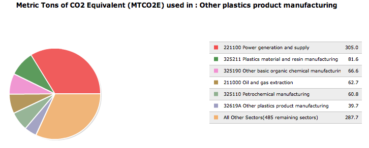
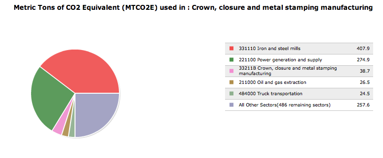
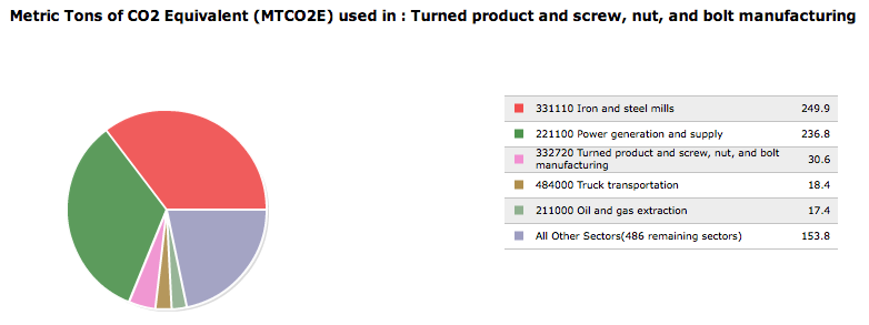
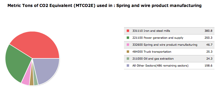
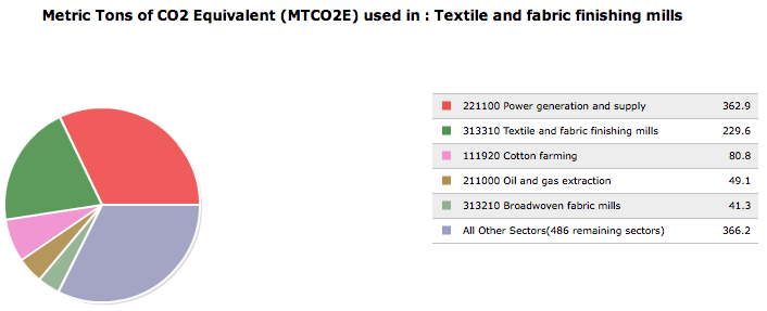
Due to the multiple ways that Umbrellas can made including sheet metal, wood, fiberglass, the Design for Environment Analysis was based solely on the the product we dissected for Phase 1. The sectors included cover the major components of the umbrella. That includes plastic manufacturing, metal manufacturing, spring manufacturing, and cloth fabrication. The analysis is based off of the Carnegie Mellon Green Institue tool: eiolca.net. The following table represents the results obtained.
| Plastic Component Manufacturing | Aluminum Component Manufacturing | Fastener/Screw Component Manufacturing | Spring Component Manufacturing | Fabric Component Manufacturing | |
|---|---|---|---|---|---|
| Item | Plastic Components | Neck and Arms | Fasteners and Screws | Springs | Waterproof Fabric |
| Sector | #32619A: Other plastics product manufacturing | #33211B: Crown, closure and metal stamping manufacturing | #332720: Turned product and screw, nut, and bolt manufacturing | #332600: Spring and wire product manufacturing | #313310: Textile and fabric finishing mills |
| Cost Per Unit | $2 | $10 | $0.50 | $1 | $2 |
| Lifetime Unit | $2 | $10 | $0.50 | $1 | $2 |
| Sector mtCO2e per $1M | 904 | 1030 | 707 | 926 | 1130 |
| Implied mtCO2e per product life | 0.001808 | 0.0103 | 3.535E-4 | 9.26E-4 | 0.00226 |
| CO2e Tax @ $30/mtCO2e | $0.05424 | $0.309 | $0.010605 | $0.02778 | $0.0678 |
- The end of life is not considered in the EIO-LCA analysis*
Assumptions were made regarding the price distribution of each component based on amount of material used and manufacturing complexity. In addition this follows the assumption that each user has one umbrella per lifetime. Under normal circumstances this number may change with unforeseen circumstances such as improper use or calamity.
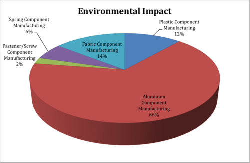
Following the data above, it is seen that the only greenhouse gas emission created is during the manufacturing of the umbrella components, as regular use does not involve any additional consumptions such as electrical use (batteries). Within the total manufacturing process, the aluminum production required for the body/shell of the umbrella produces the most greenhouse gases. While its sector [Crown, closure and metal stamping manufacturing] does not produce the largest amount of Greenhouse gases when evaluating the output per $1Million, the amount of material used in the umbrella is much greater than any other sector, resulting in 2/3 of the overall output.
To summarize, the umbrella can be separated into 5 separate sectors of the industry, with the largest sector contributing 66% (Aluminum). The overall tax placed on the greenhouse gas emmision (rounded up) per umbrella is $0.49, a small 3% of the total $15.50 price.
| DFE Guideline | Good Aspects of Competitor Product and Ideas for Improvement |
|---|---|
| 0. New Concept Development |
|
| 1. Select Low Impact Materials |
Ideas For Improvement:
|
| 2. Reduce Material Amount |
Ideas For Improvement:
|
| 3. Eco-Manufacturing |
|
| 4. Optimize Distribution |
|
| 5. Reduce Use-Phase Impact |
|
| 6. Maximize the First Life |
|
| 7. End of Life |
Room For Improvement
|
Team Member Roles
Conroy Brown: Creative Design Practicality Leader
David Carter: DFMA Leader
Lizmarie Comenencia Ortiz: Team Leader
Dennis Ou: Outreach and Development Leader
Teja Shah: FMEA Leader
Marcus Townsend: DFE Leader
References
1. Carnegie Mellon University Green Design Institute. (2012) Economic Input-Output Life Cycle Assessment (EIO-LCA) US 2002 (428) model [Internet], Available from: <http://www.eiolca.net/> [Accessed 15 September, 2012]
2. Dieter, George E., and Linda C. Schmidt. Engineering Design. 4th Edition. New York, NY: McGraw-Hill, 2009. 707-715. Print.
3. http://en.wikipedia.org/wiki/File:Parts_of_an_Umbrella.svg
4. http://en.wikipedia.org/wiki/Umbrella
5. http://www.knirps.com/en/history