Windshield wiper assembly 2
From DDL Wiki
Contents |
Report 1 - Product Analysis: Competitor Study
Executive Summary
This report details the competitor study of a 1993 Honda Civic Del Sol windshield wiper assembly with the intent of identifying method of use and production as well as opportunities for improvement. We began with a high level consideration of the product by identified key stakeholders and their major concerns. While not done qualitatively, this analysis provided insight into the needs that any redesign would need to consider. The overwhelmingly major stakeholder was the primary user prompting a user study to evaluate how the driver interacts with the product and areas where the driver may potentially misuse the product. Although the primary use of the product was intuitive to all of the users we observed, intermittent maintenance was often neglected by the user.
After these high-order analyses of the product use, we dissected the product down to individual assemblies and performed DFMA, FMEA and DFE analyses. The product dissection provided insight into how the product was manufactured and showed several innovations in the design such as having an adjustable base assembly to minimize the cost of installing similar units on different vehicle models. The DFMA analysis showed that the product had been designed to minimize costs by using only one motor to drive both wipers, but was not designed to be easily assembled into the car since it needed to be accessed from multiple angles to assemble. Additionally, during this stage we generated several ideas to make the product both make the part lest costly to assembly and minimize the number of mistakes during manufacturing. A hypothetical FMEA was conducted with the most likely incident occurring being deformation of the wiper arms that prevented effective cleaning, and the most problematic failure being a broken linkage or mounting assembly that would not only make wiper assembly stop working, but also had the potential to damage the engine. Finally, a DFE was conducted, which showed that the largest impact was the fuel tax it had on the car. From this analysis, any improvements we made would be to decrease the weight and increase the products aerodynamics.
Moving forward, we will conduct more in depth market research that focuses on issues raised through these initial analyses and use the combined results to design and evaluate a better product
Major Post-Production Stakeholders
A list of the major stakeholders of the competitors product was generated as long as a listing of their primary concerns with regard to the product. The benefit of this process is the expansion it has on our own awareness of the product since the redesign will be focused on benefiting these stakeholders and addressing their concerns in the most effective manner. Additional stakeholders or stakeholder concerns, along with a more quantitative understanding of the importance of these concerns, will be generated after more market research has been completed.
- User (Car-owner who used the product to clean their windshields)
- Effective: Effective removal of water, debris, and snow (light and heavy); Wide-cleaning motion; Leaves no streaks; Wide fluid dispersal
- Long-lasting components and structure: Durable and resistant to corrosion
- Easy and cheap replacement
- Safe: No sharp edges, would not injure the user, does not damage windshield
- Aesthetically appealing
- Must work under various climates extreme conditions: Especially - does not ice over or must be easy to de-ice
- Should not obstruct visibility both during operation and during storage
- Option to store replacement blades
- Broad selection of wiper blades – Ability to customize or upgrade
- Transporter (Concerned about the ease and safety of handling)
- Light-weight
- Durable in case of rough handling
- End-assembly automotive plant (Purchases sub-assemblies from separate manufacturer)
- Cheap, light-weight, durable, long-lifetime components and structures
- Simple and quick installation/assembly
- Safety, No VOC
- Efficient packaging within the engine compartment
- Minimize power usage and aerodynamic drag
- Repair mechanic (Concerned with ease of access and failure modes)
- Standardized
- Difficult to replace, but easy to repair
- Modular
- Safe: No sharp edges, would not injure the mechanic
- Other cars on the road (Concerned with other drivers being safe)
- Effectiveness of cleaning: Water, debris, snow, or ice is not flung in a dangerous way
- Does not fail (break) catastrophically
- Safe failure mode in case of collision
- Parking police (Wipers are needed to dispense traffic tickets)
- Wiper is safe and easy to lift so as to slide ticket underneath
Product Usability Study
Early on in our analysis of the competitor product, a usability study was conducted to both learn how the product functioned and how different users interacted with it. The goals of this study were to develop an initial understanding of the wipers use as well as areas where typical users may have difficulty operating the product, fail to operate the product correctly or operate the product in an unsafe manner. Two users were tested during this stage, one of our team members and someone without an engineering background.
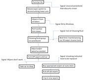
The use of these windshield wipers can be broken into two processes. The first is the process loop that involves turning on and off the wipers to clean the windshield. The second is the typically closed-loop process cycle where the user observers the need for maintenance and then at a later date fixes any observed problems. The significant steps of the each process cycles were combined into the following process flow chart including the materials and signals generated and required during use.
The first process loop is broken into the following steps. First, the driver checks the condition of the windshield for snow or ice. If there is snow he or she uses an ice scraper to clean of the windshield and clean off the wiper blades so that they work. Next, they turn on the car and, for the particular make and model of vehicle tested, shift the master lever down to turn on the wiper system. Next they adjust the speed and delay of the wipers by turning a knob inside the car. If the windshield becomes dirty, the user can use wiper fluid to clean of the windshield by using a switch inside the car. Finally, the user can turn off the wipers when they are no longer needed.
The second process loop involves intermittent maintenance either on a regular basis or as problems arise. For the use of this study we assumed that maintenance was done as needed since this was felt to be more representative of the general user and encompassed the worst case scenario. First, if the user sees that no wiper fluid is dispensed when they try to wash the windshield, they can fill up the wiper fluid tank in the engine compartment. Second, if the wiper streaks or fails to clean the windshield adequately, the user can replace the blade by pulling up the wiper blade, pulling the old blade off the clips holding it in place and pressing a new blade into the holding clips. More complex failures that are noticed by the user require taking it into a mechanic and were therefore not considered as part of the products use.
Based on this study we found that the while the general use of the product was well understood by both users, both users said they ignored issues with maintenance until a failure was noticed, and even then they both said they had delayed maintenance. This finding is problematic since dirty windshields are necessary for safe driving.
Product Function
The Windshield Wiper Assembly we find in cars today is often taken for granted. The earliest systems were purely mechanical that had to be manually operated. Later systems were operated by a vacuum motor and their speed would vary depending on throttle position. Modern systems use an electric motor to power a four-bar linkage to create a synchronized radial motion to power the wiper arms.
Certain Original Equipment Manufacturers (OEMs) have rain sensing wipers that will automatically turn on when rain is detected on the windshield. However our assembly came off of a 1993 Honda Civic Del Sol and is actuated manually by the user.
The primary function for a windshield wiper assembly is the removal of water from the windshield. It may also be used to remove snow, ice, or other debris that has landed on the windshield. The assembly accomplishes this function through a series of linkages that converts the rotary motion of a motor to a cyclic, back-and-forth motion. The motor drives a worm gear which is connected to a bevel gear assembly. This then rotates the axis of motion by 90° and allows for more compact packaging. This motion is used to drive four linkages, ending at the wiper blade. Only the shortest link that connects to the motor rotates 360°. The rest of the linkages do not rotate 360° and therefore provide non-continuous motion.
Dissection Exercise
Dissection Write Up
This section highlights the process used to reverse engineer the competitor’s windshield wiper shown. This reverse engineering exercise dual objectives; first, it helped give an understanding of the function of the product and the manufacturing process used to create this product, secondly, it helped identify weaknesses in the design that may be developed into opportunities for design improvement.
Based on function, we disassembled the product into the following sub-assemblies; Base substructure, large and small vibration mounts, 4 arms, gear casing, motor and the wiper. By taking a higher level view and observing these sub-assemblies and their interactions, we were able to fully develop the function structure diagram that is displayed in our usability study. By taking a closer view by dissecting and analyzing each component of the sub-assembly, we were able to create an assembly process for the entire structure.
Assembly Function
This section will document the how the wipers for a 1993 Honda Civic Del Sol function. Included in this analysis is the 4 bar linkage, the base, transmission, parts of the motor, and the wiper arms; extrapolation will be used to deduce how the electrical control system works.
A single motor drives the entire process through a work gear which turns a gear assembly creating slower rotational force. The final gear is attached directly to Arm Linkage 1 which rotates the driver side wiper. A four bar linkage is used to connect the passenger side wiper arm to the driver side arm. The advantage of this system is it allows the passenger side wiper to move in unison with the driver side without the need for an additional motor. Additionally, with the correct linkage lengths and the two ball joints shown in the table, the assembly is able to rotate both forward and backwards without changing the motor speed or direction. This was our most outstanding finding of the dissection exercise since we has assumed the control system for the wipers was electrical and not mechanical which would have greatly reduced product life since the motor would have to start and stop more frequently. After the rotating force is created on two of the linkages, the wiper arms rotate along the windshield plane and are against the glass with springs attached in the and the short linkages.
This four-bar linkage system, as well as the motor and transmission, are held in the car by the base assembly which consists of a center plate, supporting arm and two mounting plates. The major finding of this assembly is the mounting plates which are cast and the most expensive part of the base are attached to the product with a standard-purchase bar. This both reduces manufacturing costs and allows the plant to use the same assembly across different makes and models by simply replacing the length of the support bar. These mounting plates were attached to the body with vibration dampening grommets that prevented excessive wear from the engine running and road vibrations.
Dissection Table
DFMA
During the design process, an engineer does not only consider the structural soundness and kinematics of the mechanism. Manufacturing and assembly processes must be accounted for as well, since these factors can add significant cost to the final product if not efficiently executed. Design for Manufacturing (DFM) and Design for Assembly (DFA) analysis provides a summary of areas where manufacturing and assembly considerations were incorporated, or not incorporated, into the design.
The tables below indicate that many components of the windshield wiper assembly were designed with manufacturing and assembly in mind. A few highlights include a clever 3-piece base to commonize the product line and using ball joints at the ends of the linkages to allow for looser tolerances and out-of-plane linkage movement. While most of the design facilitated manufacturing and assembly, there are a set of screws to secure the gearbox that are difficult to access, and would require the assembly be turned over.
Manufacturing
| Design for Manufacturing | |
|---|---|
| Guideline | Comments |
| Minimize Part Count Eliminate fasteners, part consolidation | One motor Remove extra bolts Complex linkage can be replaced by another motor
|
| Standardize Components Take advantage of economies of scale & known component properties | Different bolt sizes Different sized grommets that performed similar functions Standardized C-channel and tube size Standardized motor Standardized cast housing |
| Commonize Product Line Economies of scale and minimum training and equipment | Same wiper assembly can be used in different vehicle models because of adjustable base length Cast parts remain the same; mold can be reused |
| Standardize Design Feature Common dimensions for fewer tools and setups | Different screws all have the same head; only requires one type of screwdriver head |
| Keep Designs Simple Simplest way to achieve needed functionality | Utilizes a constant, forward rotation of motor to achieve cyclic motion |
| Multifunctional Parts e.g.: fingernail clipper | Four-bar linkage both achieves desired motion & connects the wipers |
| Ease of Fabrication Choose materials easy to work with | Uses common metals (aluminum & steel) Uses common rubber for vibration isolation |
| Avoid Tight Tolerances Causes exponential cost increases | Ball joints at ends of linkages allow for twisting & other non-planar motion within assembly without stressing parts Four-bar linkage arms have enough phase offset to allow for looser tolerance in linkage arm lengths |
| Minimize Secondary & Finishing Operations Only where needed | Assembly is typically hidden, so aesthetic finishes are unnecessary |
| Take Advantage of Special Process Properties e.g.: color in injection molding | Cast parts have ribs & optimized shape - does not add much complexity to casting process Text on cast parts(?) |
Assembly
| Design for Assembly | |
|---|---|
| Guideline | Comments |
| Minimize Part Count Eliminate fasteners, part consolidation | Three-piece housing can be cast as one Two motors can eliminate the need for a four-bar linkage
|
| Minimize Assembly Surfaces and sequence them | Motor + gearbox are mounted on reverse side of linkages Grommets must be installed from sides of the assembly |
| Use Subassemblies can be assembled and tested separately, can be outsourced | Motor + gearbox are preassembled Three-piece housing can be preassembled |
| Mistake-Proof unambiguous, unique assembly orientation | Linkage arms are not labelled; their different lengths can lead to confusion during assembly No way to orient the cast housings |
| Minimize Fasteners snap fits and part consolidation | Staked ends on pins Ball joints are staked in linkage ends |
| Minimize Handling position for insertion or joining is easy to achieve | Fasteners are not all accessible from one side |
| Provide Unobstructed Access consider assembly path (e.g.: oil filter) | Motor housing screws are difficult to access |
| Maximize Assembly Compliance chamfers and radii help assemble parts with variance | Rubber grommet seats have rounded ends to guide installation |
FMEA
A Failure Mode and Effects Analysis (FMEA) is a technique used by engineers to identify potential problems with new or existing designs and identify which require the most immediate attentiion. "FMEA identifies the mode of failure of every component in a system and determines the effect on the system of each potential failure." (Dieter & Schmidt). In our analysis, the Wiper Arm and Wiper Spring generated the highest RPNs (risk priority number) and would therefore be given priority action. Each RPN is calculated by multiplying the Severity (S) x Occurance (O) x Detection (D). The table below scores out each failure mode.
| Failure Mode and Effects Analysis | |||||||||
|---|---|---|---|---|---|---|---|---|---|
| Item & Function | Failure Mode | Effects of Failure | S | Causes of Failure | O | Design Controls | D | RPN | Recommended Actions |
| DC Motor | Gear teeth stripped from excessive wear Gears out of alignment | Costly repair Temporarily inoperable | 7 | Excessive torque Obstruction on arm Body vibrations | 1 | Durability tests | 2 | 14 | Fail-safe built into motor control to shut down motor when excessive torque is detected |
| Linkages | Misalignment in assembly Shearing of steel tube | Costly repair Temporarily inoperable Possible damage to components within the engine bay | 7 | Improper installation Environmental degradation | 2 | Durability tests | 1 | 14 | Clear markings or part geometry that only allows one assembly orientation |
| Ball Joints | Ball becomes detached from joint Ball seizes in joint | Costly repair Temporarily inoperable | 7 | Debris Linkage misalignment Random forces | 2 | Dimension checks with gages Dye penetrant to check for adequate lubrication | 2 | 28 | Locker ring to prevent detachment Maintenance checks for adequate lubrication |
| Wiper Arm | Elastic deformation | Reduced wiping effectiveness | 5 | Impact from flying debris User error Weather Damage from carwash | 4 | Stress tests | 4 | 80 | Recess arm beneath car hood Increase plastic strength |
| Mounting Assembly | Detachment from body Grommet failiure | Damage to other components in the engine bay Reduced effectiveness | 8 | Loosened from body vibrations Bad installation Corrosion | 1 | Durability Tests Electrical sensor | 4 | 24 | Specify correct materials Allow for maintainance Progressive, controlled failure |
| Wiper Blades | Tearing | Reduced ability to effectively clean the windshield | 5 | Material failure from high-cycle fatigue | 5 | Easily replaceable | 1 | 25 | Second blade Thicker rubber reinforcement where wiper blade attaches to wiper arm |
| Wiper Arm Spring | High-cycle fatigue Yielding | Allowing wiper arms to move away form windshield, preventing them from clearing the windshield of water | 5 | Debris on windshield getting wedged in the spring Pulling the wiper arms too far away from the windshield during cleaing | 4 | Durability tests of spring | 5 | 100 | More durable spring Use a torsion bar |
DFE
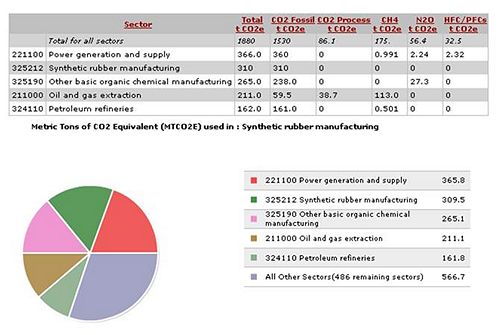
After conducting a design for environment analysis on the competitor's windshield wiper, we discovered that the wiper system's largest effect on the environment is the greenhouse gas emissions through the burning of petroleum in the use phase of the product. Other significant damaging effects on the environment are present during the production phase by way of greenhouse gas emissions and energy consumption through the manufacture of synthetic rubber and the manufacture of the windshield wiper system. Thus, after completing our DFE analysis, one major design improvement that can significantly lessen environmental impacts due to GHG emissions and energy consumption is reducing use phase power draw. This can be accomplished by increasing the efficiency of power transmission or reducing friction in drivetrain components or between linkage arms.
In the first section of our DFE analysis, we applied DFE guidelines to provoke areas of improvement in the wiper system design. The results are included below, however notable sources of improvement with respect to the environment are reducing the number of components either through eliminating linkages or entire wiper arms and enabling easier disassembly to make the steel and aluminum easier to recycle at end of life.
| Design for Environment | |
|---|---|
| DFE Guideline | Suggestions for Improvement |
| 0. New Concept Development De-materialization, Functional optimization | -hydrophobic windshield -blowing a film of air -heated windshield/wipers/fluid |
| 1. Select Low Impact Materials Avoid toxics and ozone depleters, Use renewable, recycled, recyclable materials | - toxicity of the ethanol or methanol mixture of wiper fluid may be harmful when breathed in or ingested - disposal of fluid may lead to air or water pollution - fluid may corrode paint, rubber, wax, or plastic components |
| 2. Reduce Material Amount Reduce weight, transport volume | - depending on model of car, one wiper may clean effectively - designing system with two separate motors for each wiper would remove body connection and additional linkages |
| 3. Eco-Manufacturing Alternate production processes, reduce production waste | |
| 4. Optimize Distribution Less/cleaner/reusable packaging | |
| 5. Reduce Use-Phase Impact Lower energy consumption, reduce consumables | - maximize the efficiency of the wiper fluid pressure and spray pattern to reduce amount of fluid used while maintaining effective cleaning |
| 6. Maximize The First Life Increase durability, easy maintenance and repair | - design rubber vibration mounts to last lifetime of car
- since linkage assembly may be hidden underneath chassis, design structural components to last throughout lifetime |
| 7. End of Life Recycling, Design for Disassembly, Reuse of product, Re-manufacturing | - system can be easier to disassemble to make recycling of metal and rubber more desirable |
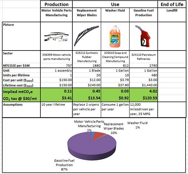
The first step in our Life Cycle Analysis was to list the materials involved in each stage of the wiper system's life. These results are included in the table below. For the purposes of our LCA, the production phase will be considered as a whole, while the use phase will be separated into the effects from the inputs of wiper blade replacement parts, washer fluid, and the combustion of gasoline.
| EIO-LCA | ||
|---|---|---|
| Life Cycle Stage | Inputs | Outputs |
| Material Extraction | Natural resources (iron ore, aluminum) | Steel, Rubber, Plastic, Aluminum Environmental Damage (GHG like CO2) |
| Production | Materials, Energy, Labor, Facilities (Machinery and Storage0 | Parts, Assemblies, Packaged goods |
| Use | Fuel to run motor Wiper Blades & Replacement parts Washer fluid | Used/damaged wiper blades Disposed washer fluid Environmental Damage (GHG like CO2) |
| End of Life | Windshield wiper assembly Washer fluid and its plastic container Replacement blades | Recyclable Components: Steel, Rubber, some Plastic Landfill waste |
| Transportation | Packaging Diesel fuel Labor | Packaging Environmental Damage (GHG like CO2) |
Energy Consumption
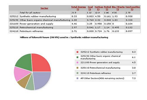
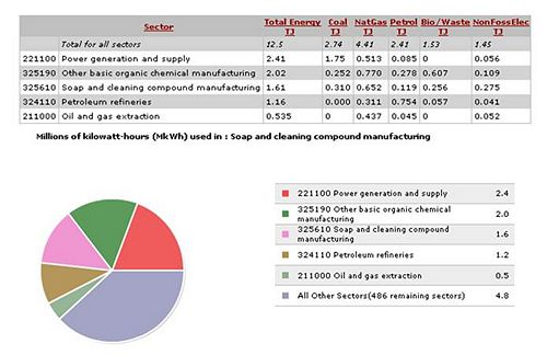
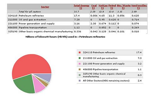
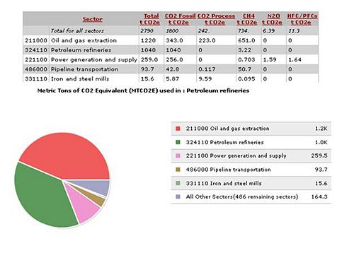
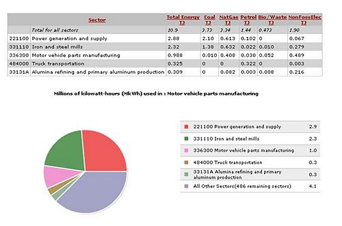
Using the Economic Input-Output Life Cycle Assessment method on EIOLCA.net [2] enabled us to quantify the energy consumption and greenhouse gas emissions generated both through the production and use phases of our product. We found that the majority of energy consumption effects was due to petroleum refineries, while synthetic rubber manufacturing and power generation and supply also had significant energy draw.
Motor Vehicle Parts Manufacturing
Greenhouse Gases
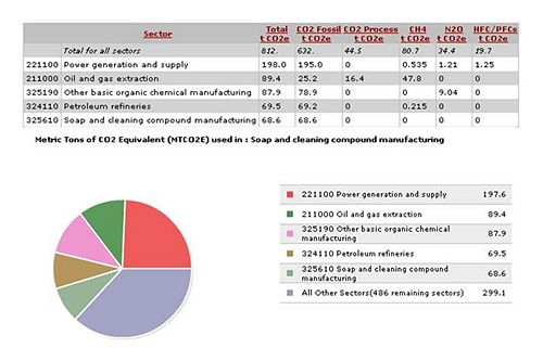
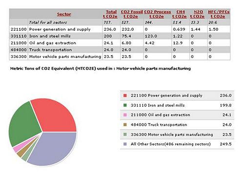
The EIOLCA models showed that the largest greenhouse gas effects came from oil and gas extraction in the production of petroleum, however power generation and supply and petroleum refineries were also significant.
Motor Vehicle Parts Manufacturing
Life Cycle Analysis
Picture copyright information: Images courtesy of [3], [4], and [5].
The results of our final EIOLCA including the production and use phases of the windshield wiper system confirms our intuition that the greatest percentage of the environmental impact is due to the use of gasoline to power the product throughout its lifetime. This impact can be mitigated through the further widespread sale of gasoline-electric hybrid vehicles or fully electric vehicles. The EIOLCA shows that synthetic rubber manufacturing and petroleum refinement have relatively similar greenhouse gas emissions in metric tons of carbon dioxide equivalent. However, because the units of gasoline per lifetime is much greater than that of wiper blades, the combustion of gasoline is shown to be the leading environmental impact of this windshield wiper system.
Team Member Roles (Report I)
The team member roles were assigned as follows by a process of individuals volunteering based on their preferences and expertise in an area:
| Team Member | Roles |
|---|---|
| Justin Whaley | Team Leader, Executive Summary, User Study, Assembly |
| Mike Lin | DFMA Lead, Dissection Photos, Product Function |
| Max Gustafson | FMEA Lead, Product Operation, Dissection summary |
| Andrew Socha | DFE Lead, Bill of Materials, Team Roles |
Each team member was present for the usability study, the dissection, and the in-class exercises. In addition to writing up the sections he was responsible for, the team leader compiled the PowerPoint presentation and scheduled weekly team meetings.
References
[1] Dieter, George Ellwood., and Linda C. Schmidt. Engineering Design. Boston: McGraw-Hill Higher Education, 2009. Print.
[2] Carnegie Mellon University Green Design Institute. (2008) Economic Input-Output Life Cycle Assessment (EIO-LCA), US 1997 Industry Benchmark model [Internet], Available from:<http://www.eiolca.net> Accessed 1 January, 2008.
[4] http://www.preparednesspro.com/blog/wp-content/uploads/2009/12/gasoline.jpg
[5] http://www2.dupont.com/Wiper_Blades/en_US/assets/images/pylon%20images/DupontStndrd.jpg

