Ansys
From DDL Wiki
| Line 15: | Line 15: | ||
| - | [[Image:Ansys2.PNG | + | [[Image:Ansys2.PNG|center|Figure 2 Created two rectangles.]] |
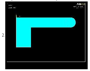
Figure 2. Created two rectangles | Figure 2. Created two rectangles | ||
Revision as of 12:12, 12 January 2007
Effect of Modelling on Ansys
Ansys is a finite element analysis software used for numerically solving static/dynamic structural problems, thermal, electromagnetics, acoustics and fluid problems. The results that are obtained reflect how the model was generated, loaded and meshed. When performing a geometry optimization using Ansys, users must take into account all of these factors. By exploring a case study, the sensitivity of Ansys to these changes can be visualized. Modelling
There are multiple ways to generate geometry in Ansys.
Figure 1. Angle Bracket
Using log files obtained from a CMU undergrad mechanical engineering course, there were two main methods in which users approached this problem.
Method 1
Figure 2. Created two rectangles
     2. [[[Image:1_2.JPG]]]
         o
Figure 3. Rounded corners
     3. [[[Image:1_3.bmp]]]
         o
Figure 4. Filleted with lines
     4. [[[Image:1_4.bmp]]]
         o
Figure 5. Filleted with lines
     5. [[[Image:1_5.bmp]]]
         o
Figure 6. Subtracted area of hole
Method 2
*
     1. [[[Image:2_1.bmp]]]
         o
Figure 7. Created arcs
     2. [[[Image:2_2.bmp]]]
         o
Figure 8. Created arcs
     3. [[[Image:2_3.bmp]]]
         o
Figure 9. Created lines
     4. [[[Image:2_4.bmp]]]
         o
Figure 10. Created area
     5. [[[Image:2_5.bmp]]]
         o
Figure 11. Subtracted area of hole
Modelling Path
[[[Image:modellingpath.JPG]]]
Figure 12. Meshing
[[[Image:meshing.JPG]]] 2/15 used an element mesh size of .25 while 13/15 used an element mesh size of .5. Figure 13. Loading
*
     6/15 users accounted for depth and applied 80 psi
   *
     8/15 used 10 psi from the diagram
   *
     1/15 did not use either
   *
All users applied 0 displacement
Results
[[[Image:meshingerror.JPG]]]
*
     With constant pressure, average difference due to modelling is 19.94%
   *
     WIth constant pressure and constant mesh size, average difference is 23%
   *
Meshing affected the results by 3%
[[[Image:pressurediff.JPG]]]
*
     Same model given two different pressures
   *
Percent difference due to pressure difference is 87.5%
Conclusion
*
     The greater the difference in modelling, the greater the difference in Ansys results.
   *
     By setting a tighter criterion for convergence, the difference due to meshing should go to zero.
   *
The same loading will produce the same results.
Links
*
     http://en.wikipedia.org/wiki/ANSYS
   *
http://computing.ee.ethz.ch/sepp/ansys-6.0-bo/structural_tut.html


