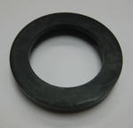
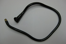
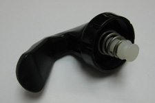
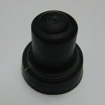
Low-foam keg tap
From DDL Wiki
(→Design Documentation) |
(→Design Documentation) |
||
| Line 29: | Line 29: | ||
|- | |- | ||
| 1 | | 1 | ||
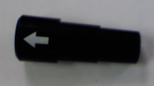
| - | | | + | | Handle |
| 1 | | 1 | ||
| 1 | | 1 | ||
| Line 35: | Line 35: | ||
| Plastic | | Plastic | ||
| Injection molding | | Injection molding | ||
| - | | | + | | - |
|- | |- | ||
| 2 | | 2 | ||
| Plunger | | Plunger | ||
| - | | | + | | 2 |
| 4.3 | | 4.3 | ||
| Forces air into casing | | Forces air into casing | ||
| Line 48: | Line 48: | ||
| 2.1 | | 2.1 | ||
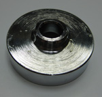
| Plunger Disc | | Plunger Disc | ||
| - | | | + | | 2 |
| 0.5 | | 0.5 | ||
| Air tight | | Air tight | ||
| Line 57: | Line 57: | ||
| 3 | | 3 | ||
| Plunger O-Ring | | Plunger O-Ring | ||
| - | | | + | | 2 |
| 0.05 | | 0.05 | ||
| Seal | | Seal | ||
| Line 67: | Line 67: | ||
| 4 | | 4 | ||
| Cylindrical Plunger Casing | | Cylindrical Plunger Casing | ||
| - | | | + | | 2 |
| 6.3 | | 6.3 | ||
| Pressure for pumping | | Pressure for pumping | ||
| Line 76: | Line 76: | ||
| 5 | | 5 | ||
| Cylindrical Casing O-Ring | | Cylindrical Casing O-Ring | ||
| - | | | + | | 2 |
| 0.05 | | 0.05 | ||
| Seal | | Seal | ||
| Line 85: | Line 85: | ||
| 6 | | 6 | ||
| Cylindrical Top | | Cylindrical Top | ||
| - | | | + | | 2 |
| 1.7 | | 1.7 | ||
| Encloses plunger in casing | | Encloses plunger in casing | ||
| Line 94: | Line 94: | ||
| 7 | | 7 | ||
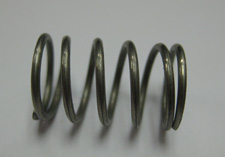
| Plunger Spring | | Plunger Spring | ||
| - | | | + | | 2 |
| 0.1 | | 0.1 | ||
| Prevents plunger from getting stuck | | Prevents plunger from getting stuck | ||
| Line 104: | Line 104: | ||
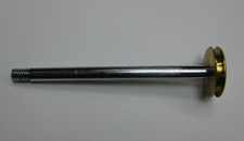
| Center Cylinder | | Center Cylinder | ||
| 1 | | 1 | ||
| - | | | + | | - |
| Separates air input from beer output | | Separates air input from beer output | ||
| Stainless Steel | | Stainless Steel | ||
| Extrusion, mill, lathe, drilled holes, machined threads | | Extrusion, mill, lathe, drilled holes, machined threads | ||
| - | | | + | | - |
|- | |- | ||
| 9 | | 9 | ||
Revision as of 17:42, 4 December 2009
Contents |
Executive Summary
Provide a brief executive summary summarizing your findings and conclusions. In particular, summarize
- Findings from market research justifying need for the new product: Survey distributed; found that users desire a lower foam output, easier pumping mechanism, and more intuitive tap design
- The product's main features, advantages over competitors, and target market: center cylinder redesigned to eliminate 90 degree bend in liquid output (straight tube means less foam), final product will include pressure gauge to prevent overpumping; competing products create more foam; target market is beer distributors and college students
- The most important findings from your product analyses that justify design choices and support your case for the new product.
Market Analysis
Make the case that there exists a market need for your product using market research findings, illustrative pictures, benchmarking against competitors, and identifying your target market. Estimate a ballpark expected price and production volume for the product and compare against expected cost. Determine if the product has high likelihood to be profitable or unprofitable or if more information is needed to determine. Is there enough potential to justify investment in further market research and testing?
Design Documentation
Include assembly drawings with all components labeled as well as a bill of materials defining each component with quantity, material, etc. Include a fully dimensioned CAD drawing for each custom component and a company and part number for each purchased component.
House of Quality
Provide a complete house of quality table to summarize your design choices, targets, relationships, and benchmarking against the competition. Highlight major findings and conclusions.
Design Analysis
Report on conclusions and recommendations from your DFMA, FMEA, and DFE findings for your product, and benchmark against the competition. Highlight major findings in the report and provide data in the appendix.
Mechanical Analysis
Clearly state the purpose of the analysis, methods and assumptions. Define all symbols, and provide a free body diagram, if applicable. Summarize conclusions and implications for you design, and explain how the analysis serves to justify your design choices.
Prototype Documentation
Document your final prototype, explain what it demonstrates about your design, and clearly identify differences between your prototype and final design intended for mass production. Summarize findings from user testing and user feedback.
Design Process
Include a short section documenting your team design process for scheduling, coordinating, and completing tasks. Identify individual team member roles, responsibilities, and contributions. Assess the state of the product. Is the design ready for production? If not, what are the next steps (eg. more testing, quantitative market research)?
Appendix
Include Design analysis data here.
