Ski boot walking attachment initial
From DDL Wiki
(Add roles) |
(Faces) |
||
| Line 468: | Line 468: | ||
==Contributors== | ==Contributors== | ||
| + | <gallery widths="180px" heights="180px" perrow="4"> | ||
| + | Image:Skiboot-face_brandon.jpg|Brandon | ||
| + | Image:Skiboot-face_randy.jpg|Randy | ||
| + | Image:Skiboot-face_richard.jpg|Taka | ||
| + | Image:Skiboot-face_jarrett.jpg|Jarrett | ||
| + | </gallery> | ||
*Brandon Perry '''(Group Leader)''' | *Brandon Perry '''(Group Leader)''' | ||
Revision as of 09:57, 22 September 2008
Executive summary goes here. (Waiting for other content.)
Brandon
Contents |
Needs & Stakeholders
Overview
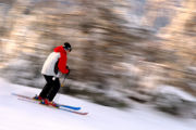
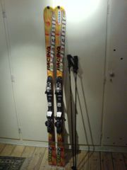
Alpine skiing is a popular sport worldwide. The premise is nothing more than affixing stiff runners to one’s feet and proceeding down the side of a mountain to the equipment installed to transport the skier uphill for another round of downhill skiing. However, such a simple sport has ballooned into a multi-billion dollar industry. Every year, some 6.3 million Americans visit the 481 alpine skiing resorts operating in the United States<ref>National Ski Areas Association. "Industry Stats." <http://www.nsaa.org/nsaa/press>.</ref>. They spend, on average, 9 days on the slopes. Their ages span from pediatric to geriatric, averaging to 33. The ski mountains frequented by day are often surrounded by a resort village sized to accommodate the large amount of often wealthy tourists. As many once-booming coal towns became ghost towns once the coal supply was exhausted, these ski towns would face certain downsizing and restructuring were the ski industry to collapse<ref>"Mild Winter Affects the Economy." Vermont Business Magazine. May 2007. <http://findarticles.com/p/articles/mi_qa3675/is_200705/ai_n19430501/pg_5></ref>. These owners, proprietors, and employees are dependent on an industry of enjoyment.
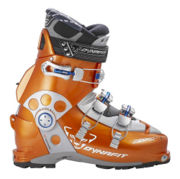
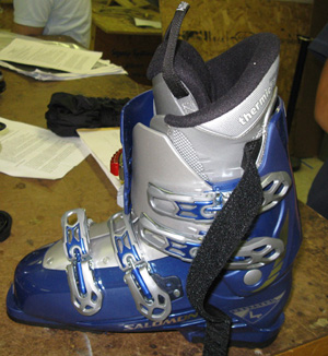
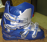
Downhill skiing would not be possible without its namesake equipment, the ski. In turn, a ski is useless without a way to attach it to the human body. The ski boot fulfills this surprisingly complicated role. Skis generate forces and moments in all directions upon the foot, and the rider exerts forces upon the skis to turn, jump, and stop. Boots must strike a balance between weight, stiffness, comfort, and price. Quality ski boots sell for between $200 and $600 and must be fitted properly to give the skier control over the skis<ref>C.f. Alpine Ski Shop, a ski equipment retailer. <http://www.alpineskishop.com/skiboot.html>.</ref>. Ski boots are shaped largely like a normal boot, though have three major additional features. First, ski boots must largely immobilize the ankle. Pressure from the shin against the tall tongue of the boot is necessary for ski control, so a rigid boot is necessary to transmit that force. Second, these rigid boots use metal buckles to tighten their exoskeleton around the foot. Buckles provide a convenient method of tightening and loosening the boots as necessary, for wear and for removal. Third, ski boots must attach to the skis. In the early days of skiing, boots were clamped securely to skis with no means of emergency detachment<ref>SkiingHistory.org: "The First Release Bindings."<http://www.skiinghistory.org/releasebindings.html></ref>. After the problem of broken legs and ankles arose, emergency-detach ‘bindings’ were developed to allow a ski to break free of a (crashing) skier. Modern bindings (and thus, modern boots as well) follow a standardized interface design. A hard heel and toe of the boot are mandatory, as are slight protrusions from the heel and toe.
The heel and toe hardness, along with the ankle stiffness, make walking in ski boots a harrowing task (more on this below). Walking is a necessity: upon arriving at the ski slope, the typical skier will put on his ski boots, place his shoes in a locker - lest he carry them - and proceed – skis in hand – across an icy surface to the ski slope. Crowds and stairs are frequent obstacles. Ski boots commonly include treaded pads on the sole to improve traction on slippery surfaces. And, in an attempt to regain ankle mobility, a universal solution is to unbuckle the boots. As a tradeoff for ankle flexibility, the foot is exposed to cold air and snow; small children and novice skiers may be unable to re-buckle their own boots. And in the end, walking is still awkward.
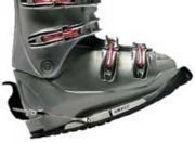
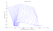
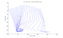
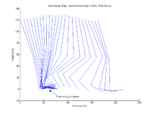
[diagrams]
This walking problem is a nuisance 60 million skier-days per year. Manufacturers are tied to an industry-standard design which prevents modification of the boots themselves, and ski resorts are partially exempted from liability for personal injury<ref>"Survey of Ski Law in the United States" <http://www.skilaw.com/skilawsurvey.html></ref>. As such, the consumer (wearer) is the party most directly affected by the difficulty of walking. With 40% of the skiing population having a household income of over $100,000, these consumers have the economic means to purchase or rent additional beneficial equipment, such as inexpensive, convenient attachments to make walking easier.
Detail: Kinesiology of Walking
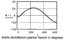
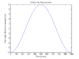
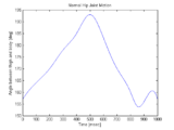
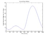
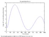
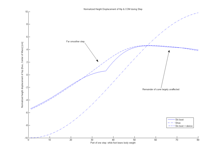
During the normal human walking gait, periods of two-foot ground contact are separated by longer periods of one-foot contact. These long periods are when the front foot takes the weight load from the rear foot and the rear foot swings forward to take the next step. During this process of taking a step, the ankle flexes to control body height and shin-to-foot angle, and to provide forward propulsion.<ref>Soutas-Little, Robert. "Motion Analysis and Biomechanics." <http://www.laboratorium.dist.unige.it/~piero/Teaching/Gait/SOUTAS-LITTLE%20Motion%20Analysis%20and%20Biomechanics.htm></ref> (see above).
However, while immobilized in a ski boot, the ankle is unable to flex. This alters the walking gait and changes the procession of the body's center of gravity relative to the point of load on the sole.
In light of the aforementioned difficulty, risks, and necessity of walking with locked ankles, there is a need for a solution to this awkward gait modification.
Product Use & Function
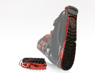
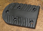
Not surprisingly, an inexpensive attachment to facilitate walking does exist. The attachment replaces the flat walking surface of the ski boot with a curved surface which smoothes the stride. And, unlike the boot sole, it can be cushioned and can use materials selected to provide increased traction.
Major Functions
- Smooth the stride
- Traction
- Cushioning
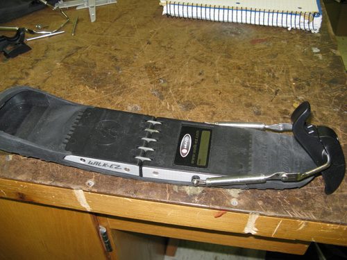
[diagrams]
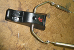
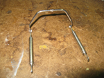
The device attaches to the standard binding tongues on the ski boot using a simple clip mechanism found on other ski products. It can be installed and removed quickly with the flip of a lever: the toe tongue of the boot is placed in the front orifice, the heel tongue is set in place, and a lever is tightened to secure the boot to the device. For the sake of convenience, it folds in half for easy stowage when not in use. It feels and appears rugged enough to support the repetitive stresses of the user’s weight, yet the design is reasonably lightweight, as carrying heavy gear while on the slopes is unpopular.
Major Characteristics
- Lightweight
- Simple
- Easy to install & remove
- Rugged
Bill of Materials
The following is the list of materials directly involved with the project we are undertaking. This means that the walking attachment itself was completely disassembled and each of its components is thoroughly described in the following table. We feel that the details of the boot itself are not necessary for the purpose of our analysis. The boot is designed a certain way for use with skiing, and since it is beyond the scope of our project to redesign the boot itself, we've only analyzed the big pieces of the boot and the area which directly contacts the walking attachment.
Walking Attachment
The following tables contains information about the walking attachment itself. The walking attachment weighs 543.3 g.
Ski Boot
The follwing table contains the important parts of the ski boot. The ski boot itself weighs 1885.5 g.
Design for X
“Design for X” (DFX) analyses of a product evaluates the efficiency of the product design from various perspectives. In this report, three major analyses are conducted on several individual components and sub-assemblies of the ski boot and the walking attachment – “Design for Manufacture” (DFM), “Design for Assembly” (DFA), and “Design for Environment” (DFE). By conducting three types of DFX analyses, the overall efficiency of the product design during the manufacturing stage (DFM), assembly process (DFA), and post end-use impact to the environment (DFE) will be determined.
Design for Manufacture (DFM)
The design for manufacture analysis discusses how individual components of the ski boot and the walking attachment were designed in order to minimize the time and cost of manufacturing process. The product design can be optimized for manufacturing process through (1) reducing the number of components, (2) homogenizing the components, or (3) redesigning of the component. Reducing number of components or homogenizing the components cuts the capital cost of production as fewer numbers of machineries are required to manufacture the product. On the other hand, redesigning of the product aims to reduce the material cost per unit product by subtracting the unnecessary portions (deadweights) of the components from the original design. The following analyses on the main components of the ski boot and the walking attachment discuss the three features (listed above) of the components that optimize the product design.
Ski Boot:
The components of ski boot could be divided into five major components (and sub-assemblies) – the plastic Ski Boot Shell with four sets of locking mechanisms per boot (1), the plastic Ski Boot Insert (2), Ski Boot Liner (3), and front and rear Rubber Plates (4), (5). In the following analyses discuss the design features that optimize the efficiency of manufacturing process, displayed by following components (and sub-assemblies) are discussed –the locking mechanisms of Ski Boot Shell, and Front and Rear Ski Boot Plates.
Locking mechanisms (1) – Each boot has four sets of locking mechanisms (sub-assemblies) that consist of a geared belt and a spring loaded hook that hold the two sides of the boot tight to provide better fit for users. For more user friendly design, one of the buckling mechanisms (the bottom buckling mechanism of high ankle component) needs to have a rotating hook. However, manufacturing rotating hook requires production of two parts (the outer frame that will secure the hook to the boot and an inner hook that locks on the channel). In order to reduce the cost of manufacturing, the ski boot uses two rotating hooks and two rigid hooks as opposed to using four rotating hooks. Rigid hook (which is a single component as opposed to a sub-assembly) allows lower cost of manufacturing; therefore, by replacing rotating hooks with rigid ones where the hooks do not need to rotate, the manufacturing cost goes down.
What is even more interesting about the buckling mechanisms used in this particular ski boot is that as opposed to using three rigid hooks and one rotating hook (the boot only needs one hook that needs to rotate), it uses two of each. This decision was made in order to reduce the time of production. While manufacturing rigid hooks would cost less, having to manufacture three rigid hooks for every rotating hook manufactured would cause idle time for the machinery that manufactures rotating hooks. By using equal numbers of the two hooks, manufactures not only reduce the cost, but also achieve the minimum time of production achievable. For a product like a ski boot (whose market demand fluctuates from season to season), minimal time of production could be essential as that would allow the manufactures to meet volatile market demand without having to spend significant amount of inventory cost.
Thus, the locking mechanism of ski boot is an excellent example of product design features that optimize both the time and the cost of manufacturing process.
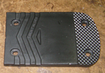
Front (4) and Back rubber plates (5) of the ski boot – Although ski boot itself requires separate castings for manufacturing right boot and left boot, the rubber plates for both feet are identical (just like the walking attachments). Both plates have the same thickness and similar pattern on the bottom (made to provide the user with more traction), suggesting that the front and the rear halves of the covers were manufactured in one casting, then cut into two separate pieces. Thus, identical designs used for both feet; and use of one casting for manufacturing front and rear halves allow significant reduction in capital cost.
Walking Attachment:
The walking attachment of the ski boot consists of two main sub-assemblies – main body (sub-assembly 1) and, and spring loaded locking mechanism (sub-assembly 2). Unlike the ski boot, the walking attachment design is identical for both right and left foot. This allows significant amount of capital cost reduction as only one set of castings are needed for main body frames (1), (2), and other components of the product can be homogenized – both resulting in reduction of capital cost. Following DFM analyses discuss the design features of each sub-assembly.
Front (1) and Back Frames (2) of the main body – The main body frames of the walking attachment provide the user with better traction and more comfort during walking process than a normal ski boots do. These components are made of rubber to allow reasonable amount of elastic deformation under operations to serve as cushions that absorb impact of landing while providing the user’s feet with sufficient support. As mentioned above, homogenous design of the walking attachment for both feet allows a significant reduction in capital cost of the main body frames. The main body frames also feature designers’ effort to reduce the material cost of the product. The components have series of triangular vacancies at areas, where the stress concentration from the load (body weight (live load) of the user) is relatively low. By subtracting those triangular sections from the components, the main body frame design achieves reduced amount of rubber, which lead to not only lower material cost but also a more user-friendly, lighter product.
Spring loaded adjustable locking mechanism (sub-assembly 2) – A simple design of the locking mechanism (sub-assembly 2) display optimal design features for manufacturing process approached both through homogenizing and minimizing number of components and through removing unnecessary materials. The simple, symmetric design of the Metal Frame assembly (sub-assembly 2-a) leads to minimum number of components, most of which are homogenized. Every component in the sub-assembly – with the exceptions of Metal Frame Arc (15) and Clip Attachment (16) – are manufactured in a pair for each unit of sub-assembly. On the other hand, the Plastic Clip assembly (sub-assembly 2-a) design is optimized by use of the minimal amount of material. Significant portions of the Large (7) and Small Clips (8) are removed to minimize the material cost.
Design for Assembly (DFA)
A design for assembly analysis discusses how each component of the product was designed to minimize the time and cost of assembly. Efficient product design for assembly involves (1) simple configurations of the assembly and (2) ease of aligning the components. Simple configuration of the components prevents confusion and misplacement during the assembly process, while ease of aligning the components speeds up the assembly. The DFA on the main components (and sub-assemblies) of the ski boot and the walking attachment are provided below.
Ski Boot:
Plastic frame of the Ski Boot Shell (1) – The bottom of the Ski Boot Shell (1) (where the Ski Boot Plates (4), (5) are put on) has series of channels so that the plates can be secured even without using screws. This allows quick and proper placement of the plates at the assembly stage. Similar design features are found inside the bottom of the Ski Boot Shell (1) that allows manufactures to secure the Ski Boot Insert (2).
Walking Attachment:
Front (1) and Back Main Body Frames (2) – The joint mechanism holding the front and back main body frames (five links (6) and a pair of pins (5)) display an excellent example of a design feature geared toward efficient assembly process. Front and back main body frame each has five channels that house the links. All the links can be lined up properly thanks to the housing, and the whole process of assembling the joint mechanism can be completed by piling through a pair of pins through already-lined up links.
Front (3) and Back Side Plates (4) of the main body – The side plates of the walking attachment main body cover the cavities in the main body frames to prevent snow from getting in. One example of a design feature that enables efficient assembly of the product is the shape of the side plates. As the plates could fit the main frame if and only if they are lined up properly, it is impossible for the components to be placed improperly. Also, the surface of the side plates facing inward has four small tips that match up with small cavities on the side of main body frames. These sets of tips and cavities enable easy and quick assembly as there is no need to secure the side plates in place while screwing them onto the main frames.
Design for Environment (DFE)
The design for environment analysis discusses how individual components of the ski boot and the walking attachment were designed in order to reduce the environmental impact of the product throughout its life-cycle. Economic Input-Output Life Cycle Assessment (EIO-LCA) is often used as a common tool for conducting a DFE analysis on a product. With the information on amount of each material used per unit product, EIO-LCA calculates how much environmental impact each unit of the product would have during its production (manufacturing and assembly), its end-usage, and after its disposal.
Design optimization of most products often puts more emphasis on DFM and DFA rather than on DFE, as reducing the time and cost of production would directly lead to greater profit. However, as environmental issues have come to draw more attentions from the public, the DFE analysis is becoming one of the significant aspects of product development that cannot be ignored.
FMEA
The table below shows several ways in which the ski boot walking attachment may fail. The item and function states the major components and their purpose, possible failure mode includes the possible ways the components may not perform as they are intended to do, effects of failure describes the consequences of the failed components, causes of failure explains the possible sources of failures, and design controls are methods in which the chance of failure mode can be reduced. S stands for severity, which is a measure of the significance of the effects of failure, O stands for occurrence, which is a measure of the likelihood that a component would fail, D stands for detection, which is a measure of the ability to detect the flaw whether during the manufacturing process or by implementing the proposed methods mentioned in design controls, and finally, RPN stands for risk priority number, which is a measure of design risk. RPN is the product of S, O, and D. The last few columns represent: recommended actions, which are the proposed methods that can be done to reduce the risk priority number, responsibility, which is a group or an individual who would be responsible for the recommended action, actions taken, which are actions that have been executed, and the updated risk priority number due to the corrective action.
| Item & Function | Failure Mode | Effects of Failure | S | Causes of Failure | O | Design Controls | D | RPN | Recommended Actions | Responsibility & Deadline | Actions Taken | S* | O* | D* | RPN* |
|---|---|---|---|---|---|---|---|---|---|---|---|---|---|---|---|
Connectors & Pins
| The pins get sheared | Product becomes unusable. One of the main supports that holds its structure fails | 8 | Excessive usage | 2 | Test Strength of pins | 1 | 16 | Add more connectors so that the weight is more distributed along the pins | Design Engineers | N/A | 8 | 1 | 1 | 8 |
| The connectors get sheared in half | Product becomes unusable. One of the main supports that holds its structure fails | 8 | Excessive usage | 2 | Test Strength of connectors | 2 | 32 | Design Engineers | N/A | 8 | 1 | 2 | 16
| ||
Soles’ Rubber Grips
| Smoothened grips | Reduces traction | 7 | Excessive sliding actions | 2 | Test the durability of the rubber | 3 | 42 | Create deeper grooves | Design Engineers | N/A | 7 | 1 | 3 | 21
|
Plastic Frames
| Brittle Fracture | Compromises structural integrity of the walking attachment | 6 | Excessive loads | 2 | Test strength of the plastic | 3 | 36 | Try different materials and choose the most practical one | Manufacturer | N/A | 6 | 1 | 3 | 18
|
Glue
| Sheared until separation occurs | Compromises structural integrity of the walking attachment | 5 | Sheared and dissolved glue | 2 | Test what solvents can dissolve the glue and the strength of the glue | 2 | 20 | Use a substance that is ideal to bond plastic with rubber | Assembler | N/A | 5 | 2 | 2 | 20
|
Metal Frame and Plastic Clip
| Brittle fracture of the plastic component | Product becomes unusable. The component that holds the ski boot with the attachment fails | 7 | Excessive force applied. Constant impacts | 2 | Test strength of plastic | 2 | 28 | Try different materials and choose the most practical one | Manufacturer | N/A | 7 | 1 | 2 | 14 |
| Sheared rivets | Product becomes unusable. Joints to fit the walking attachment into the boots fail | 7 | Excessive force and twisting motions applied | 2 | Test strength of rivets as joints | 1 | 14 | Increase the diameter of the rivets | Assembler | N/A | 7 | 1 | 1 | 7 | |
| Plastic deformation of the springs | Less degree of freedom for the clip to adjust. Will not have a flush fit with the boot | 6 | Excessive usage. Too much compression deformation | 2 | Determine the point of plastic deformation of the springs | 3 | 36 | Use hydraulic/ piston system instead of springs | Design Engineers | N/A | 6 | 2 | 3 | 36 |
Any failures that jeopardize the functionality of the walking attachment and endanger the user would receive a severity score of an eight. For example, failures in connectors and pins would result in the walking attachment to be divided in half, which is inoperable at this point. If the failures occur while someone is walking, then he/she could very well be hurt. The smoothening of the rubber grips receive a seven because the system would still be operable, but it would no longer be safe to walk on especially on slippery surfaces like ice.
Occurrence and detection are typically rated very low (between two and three) because most of the components serve a simple purpose, contain almost no complexity in their geometry, and are visible without taking anything apart. Furthermore, the only components that would have a slightly more difficult time to notice when failing are the compression springs. Each spring is located inside a hollow cylindrical chamber that is part of the metal frame, but even if one spring fails fail, it would be noticeable because the metal the piece containing the spring would not be adjustable. The occurrence values are estimated by examining the material of each component, the purpose each component serves, and the complexity of its geometry.
Analysis
Simulation
In this simulation, a simulation was simulated.
Durability Test
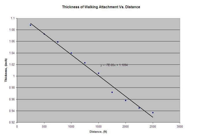
A test was done to observe the durability of the rubber grips. The conditions were that the walking attachment was dragged for 250 feet per run at roughly 5 miles per hour, under approximately 5 pounds of pressure, and against tarmac. The thickness (top flat middle section of the walking attachment to the highest protrusion of the rubber grip in the middle section of the attachment) was then measured using a caliper after every run. These conditions are considered extreme sliding conditions for the walking attachment bearing in mind that it would only experience very little sliding. If it does slide, it would be against ice, which would have a much smoother surface than tarmac.
| Run | Height of Rubber Grip(inch) |
|---|---|
| 1 | 1.088 |
| 2 | 1.073 |
| 3 | 1.059 |
| 4 | 1.040 |
| 5 | 1.023 |
| 6 | 1.005 |
| 7 | 0.972 |
| 8 | 0.958 |
| 9 | 0.945 |
| 10 | 0.937 |
The graph summarizes that the rubber grip decreases at rate 0.00007 inch per foot on tarmac under the stated conditions. We can safely say that sliding actions against the rubber grips will not affect the performance and the safety of the walking attachment. Typically, the walking attachment is exposed to surfaces such as carpet, tile, wood, and ice, in which all of them have a much smoother surface than tarmac if sliding is even a concern. The only time the skier would walk on tarmac is when he/she walks to the ski lodge from the parking lot, which is negligible. Thus, flattening of the rubber grips is not an issue which needs to be addressed in the redesign.
Contributors
- Brandon Perry (Group Leader)
- Executive Summary
- Needs & Stakeholders
- Use & Function
- Analysis: MATLAB Simulation
- Randyka Pudjoprawoto
- FMEA
- Analysis: Wear test
- Taka Matsuura
- DFM
- DFA
- DFE
- Jarrett Valeri
- BOM
- ELOCIA
References
<references />
