Lamp stand mechanical arm
From DDL Wiki
Contents |
Executive Summary
The entire lamp has been broken down and studied, but the specific interest in this lamp is the construction and function of its mechanical arm. Before taking the lamp apart, possible uses and range of motion were discussed. When taking the lamp apart, each part was photographed, weighed, and inspected for possible manufacturing process.
Consumers buy a lamp to provide light in a specific area. Consumers buy this specific lamp because of its range of motion. The user is able to change the position by simply moving the lamp to the desired position and tightening some screws. Manufacturers produce this product because a lamp is a popular piece of office equipment. This lamp was purchased for ten dollars. Its low price is very desirable for consumers and manufacturers alike because the cheaper a product is without sacrificing its integrity, the greater the number of units sold.
More will be inserted when other sections are posted.
System Function
The system is a mechanical arm that uses frictional joints to support a lamp.
The Base
The lower jaw, the threaded L bar, the thumb screw, and the upper jaw make up the base. The base unit attaches to the edge of a desk or table with the lower jaw positioned below it and the upper jaw on top. The threaded part of the L bar goes through the lower clamp then the wing nut while the shorter, unthreaded part goes through the upper clamp. The screw is used to tighten down the clamps and secure the clamp assembly to the table, fixing it from all translations and rotations. There is a hole at the top of it for a peg at the base of the arm unit.
Arm Unit
The arm has two parallel sets of equal bars that rotate at either end where it connects to plates that hold them in position relative to one another. The bottom holder has a peg on the bottom that inserts into the top of the top clamp in the base. Two of the bars attach to the bottom holder and run parallel up to the next set of joining plates. From these plates, two more bars run out of equal length up to another set of plates. These plates hold a fixture that rotates in the plane of the arm and holds the base peg of the plan unit. With this configuration of members, the top of the arm can move within a single plane that contains all the plates and members, allowing it to position along the two axes in the plane. There are screws at each joint that can be tightened to increase the friction in the joint to hold the arm in its current position.
Lamp Housing Unit
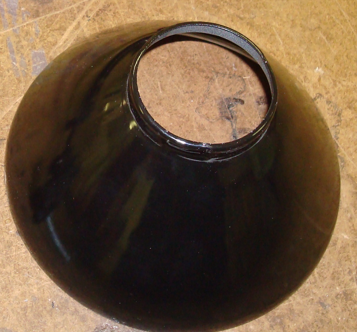
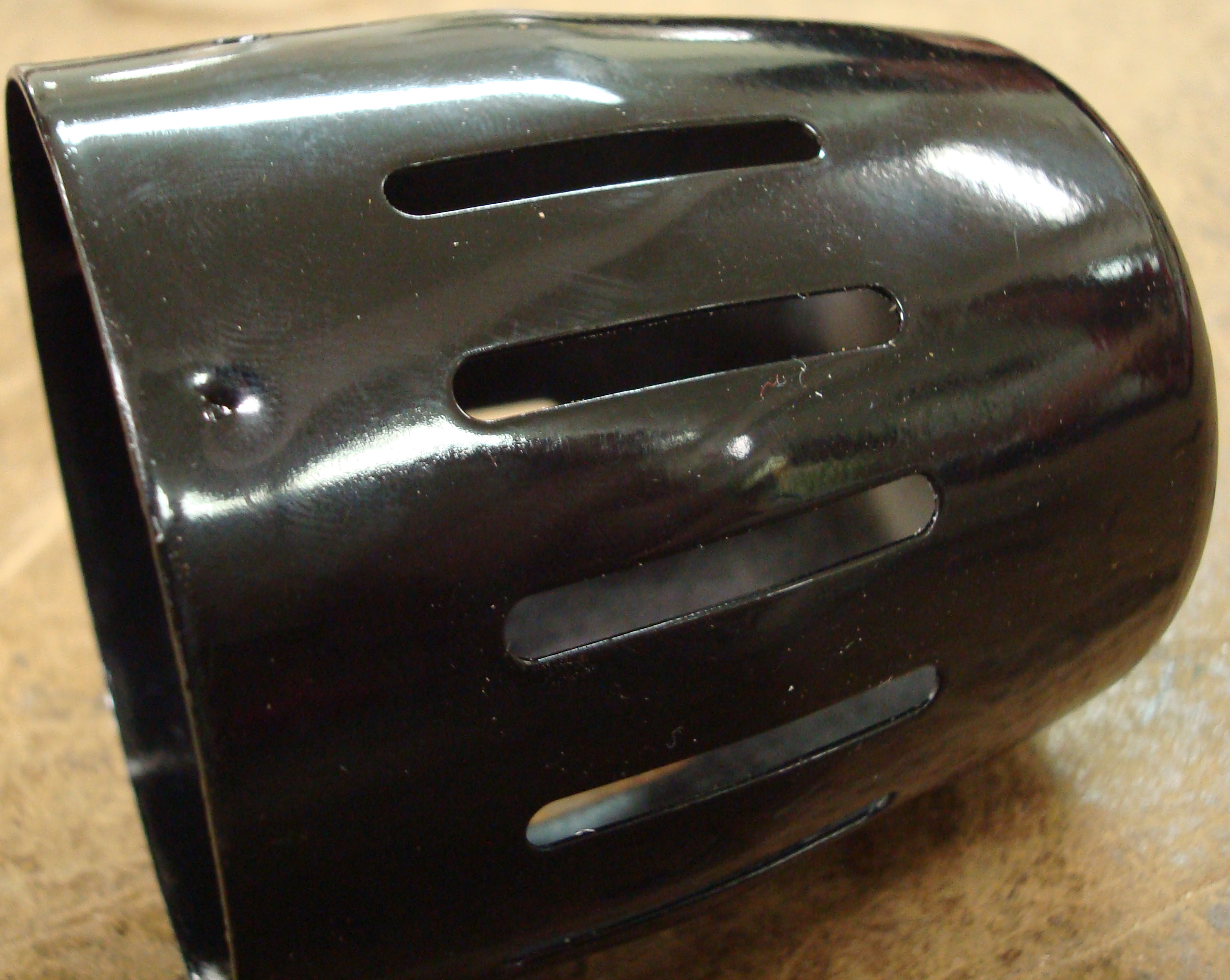
The lamp housing attaches to the arm with a peg that can rotate about its axis. This peg is screwed to the metal cup shaped housing that holds the fixture that the light screws into. There are holes cut in this part to allow heat dissipation from the lamp. A bowl shaped metal part is inserted and twisted into the opening of the cup to attach it. It serves to focus the light emitted from the bulb so that it may be directed and prevent it from blinding the user.
The Electrical Unit
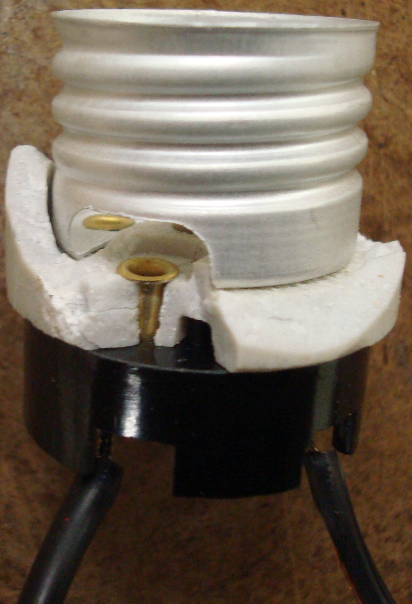
The electrical unit has its most complex components within the Lamp Housing Unit. There is a threaded metal part that is made to allow for the insertion and securing of a light bulb. This part is riveted to a ceramic isolative part and further through to the switching assembly. The switch, when rotated, turns a small pin normal to its axis, causing it to contact two metal fingers, completing the circuit to turn on the lamp. To this switching assembly runs the power cable from outside the cup of the lamp housing to the switching assembly to provide power to the system. This cable runs down the upper members of the arm unit to the base of the arm unit where there are an additional six feet of cable with a typical 2 prong AC plug.
Mechanical Analysis
For the mechanical analysis, the friction generated by the thumb screws will be tested for different tightening conditions under which their friction force provided will be tested. Ultimately, the maximum strength of the joints will be evaluated and parametized. The hope is to compare this $10 model to a $50 model that includes springs in its design to counter the weight of the lamp. The lamp will be tightened to the point of contact and given a single full turn of tightening and tested. After each test, the screw will be tightened to contact and tightened an additional turn until it shows visual signs of yielding within the member or it cannot be tightened further without mechanical failure of a component.
Components
| Part # | Part Name | Qty | Mass (g) | Function | Manufacturing Process | Material | Image |
|---|---|---|---|---|---|---|---|
| 01 | Electric Cord | 1 | 114 | to transmit electricity from outlet to lightbulb | extrusion, cutting | aluminum, plastic, electric wires |  |
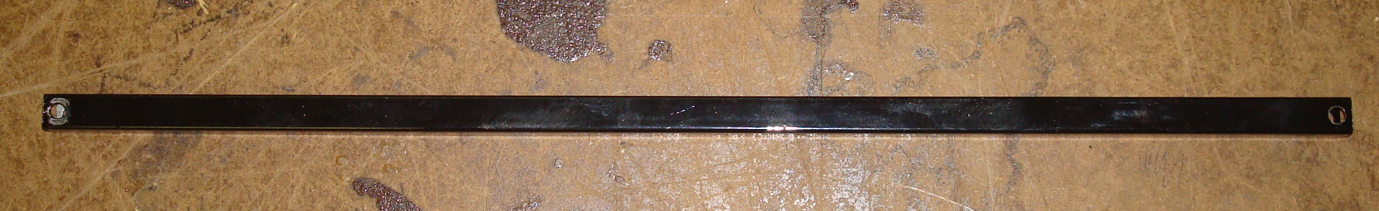
| 02 | Non-Cord Containing Rod | 1 | 48.19 | to increase distance from base to lightbulb | extrusion, machining | aluminum | Non-Cord Containing Rod |
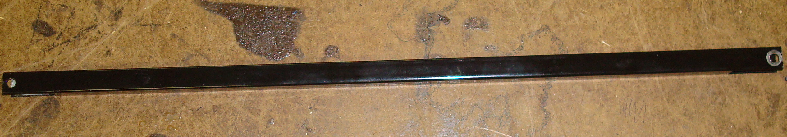
| 03 | Cord Containing Rod | 1 | 45.36 | to increase distance from base to lightbulb and contain electric cord | extrusion, stamping, machining | aluminum | Cord Containing Rod |
| 04 | Lamp Hood | 1 | 158.76 | to project and focus light from lightbulb | stamping | aluminum | Lamp Hood |
| 05 | Base | 1 | 17.01 | to mount lamp on a flat surface | injection molding | plastic | Base |
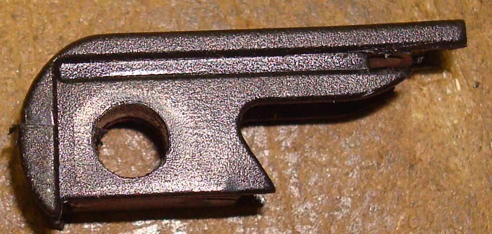
| 06 | Base Clamp | 1 | 8.5 | to hold base onto a flat surface | injection molding | plastic | Base Clamp |
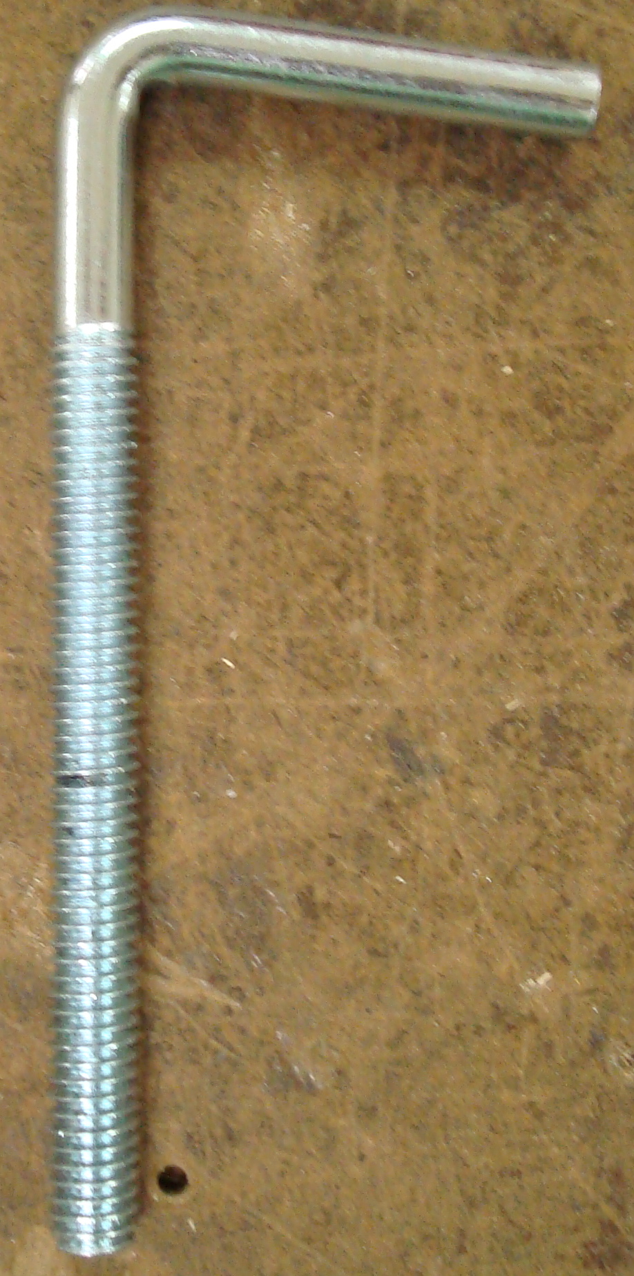
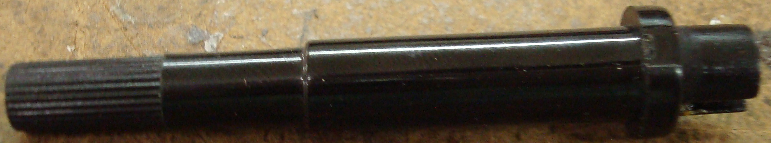
| 07 | Elbow Screw | 1 | 39.69 | to adjust clamp on base | pressing, tapping | aluminum | Elbow Screw |
| 08 | Cord Containing Rod End Cap | 4 | 0.9355 | to cover end of rod and to guide electric cord | injection molding | plastic | Cord Containing Rod End Cap |
| 09 | Non-Cord Containing Rod End Cap | 4 | 0.4706 | to cover end of rod | injection molding | plastic | Non-Cord Containing Rod End Cap |
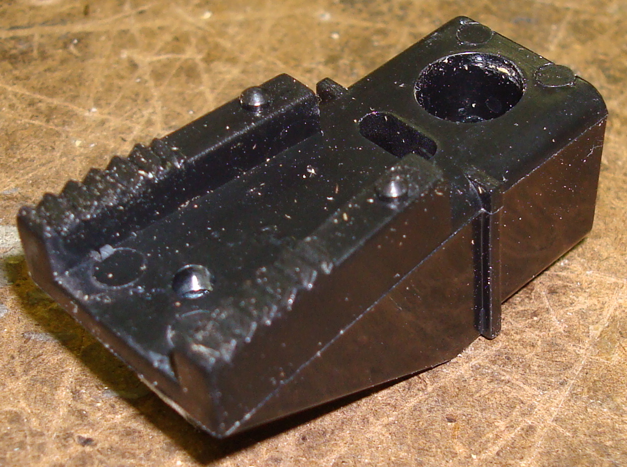
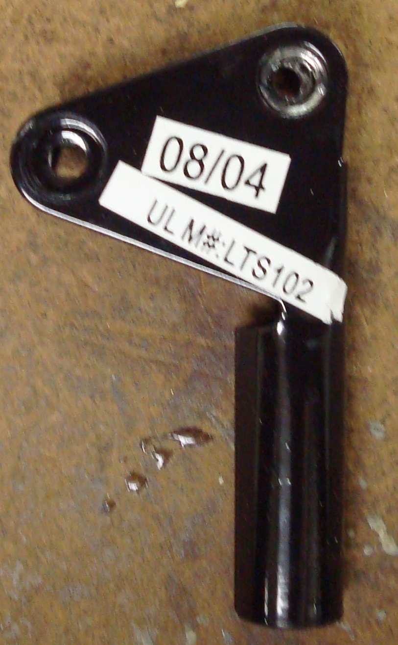
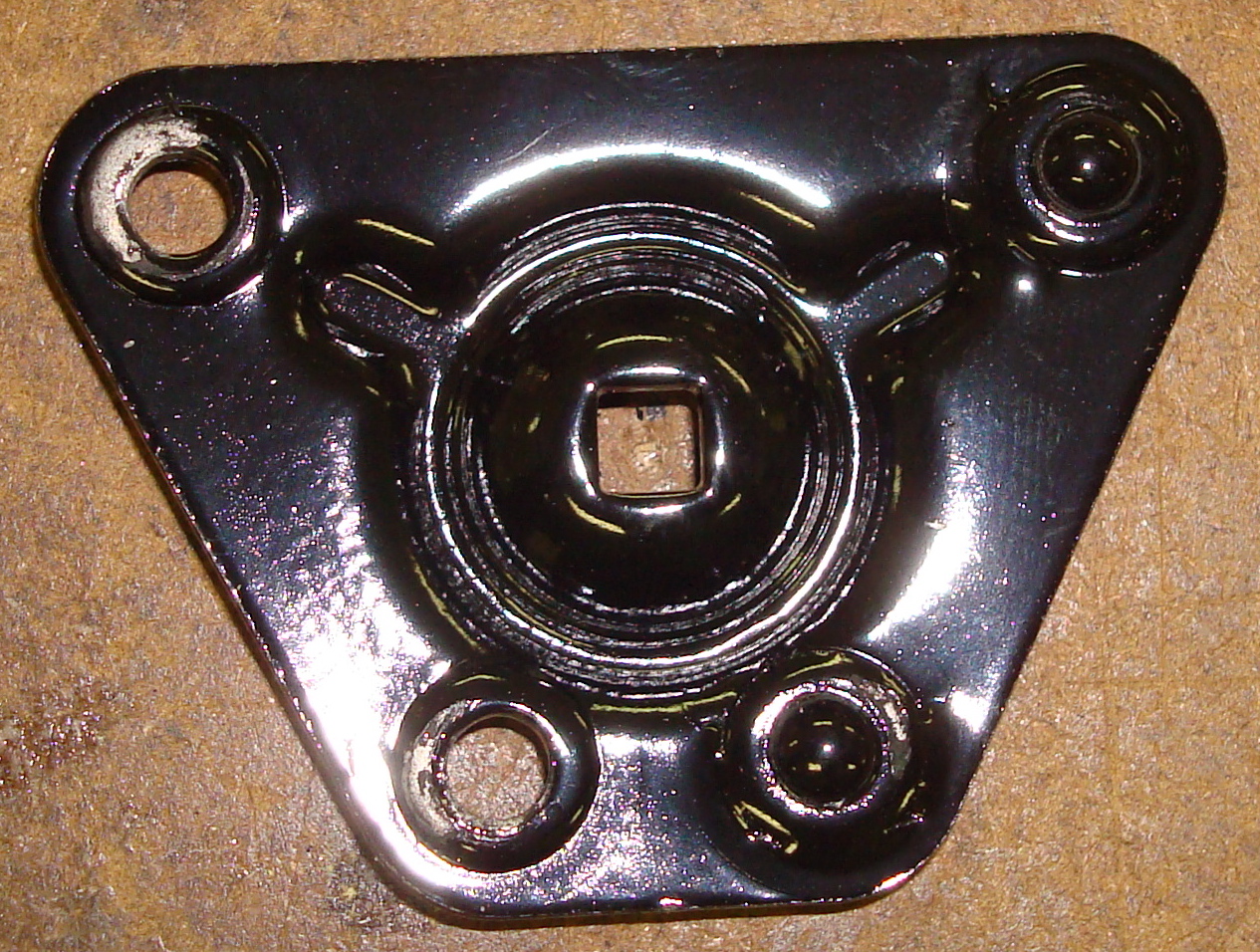
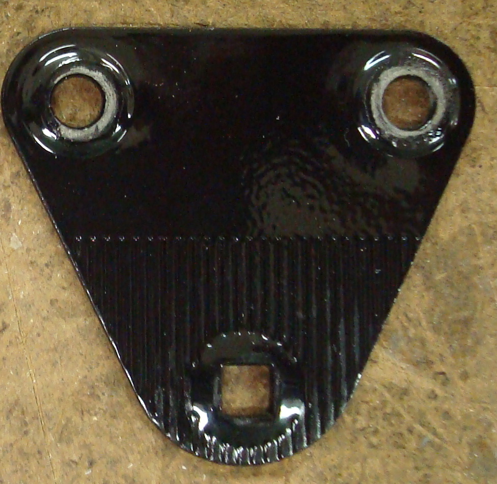
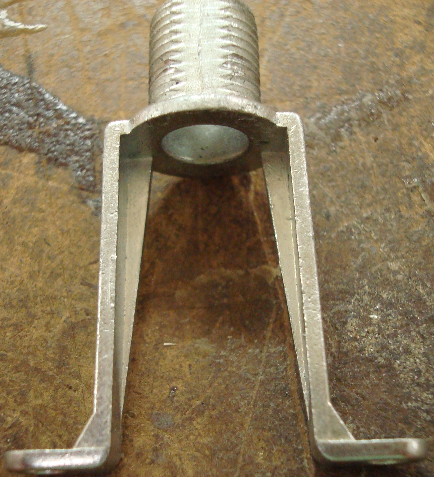
| 10 | Joint 1 | 1 | 22.68 | to attach lamp to base and adjust position | stamping | aluminum | Joint 1 |
| 11 | Joint 2 | 2 | 14.18 | to attach bottom rods to top rods and adjust position | stamping | aluminum | Joint 2 |
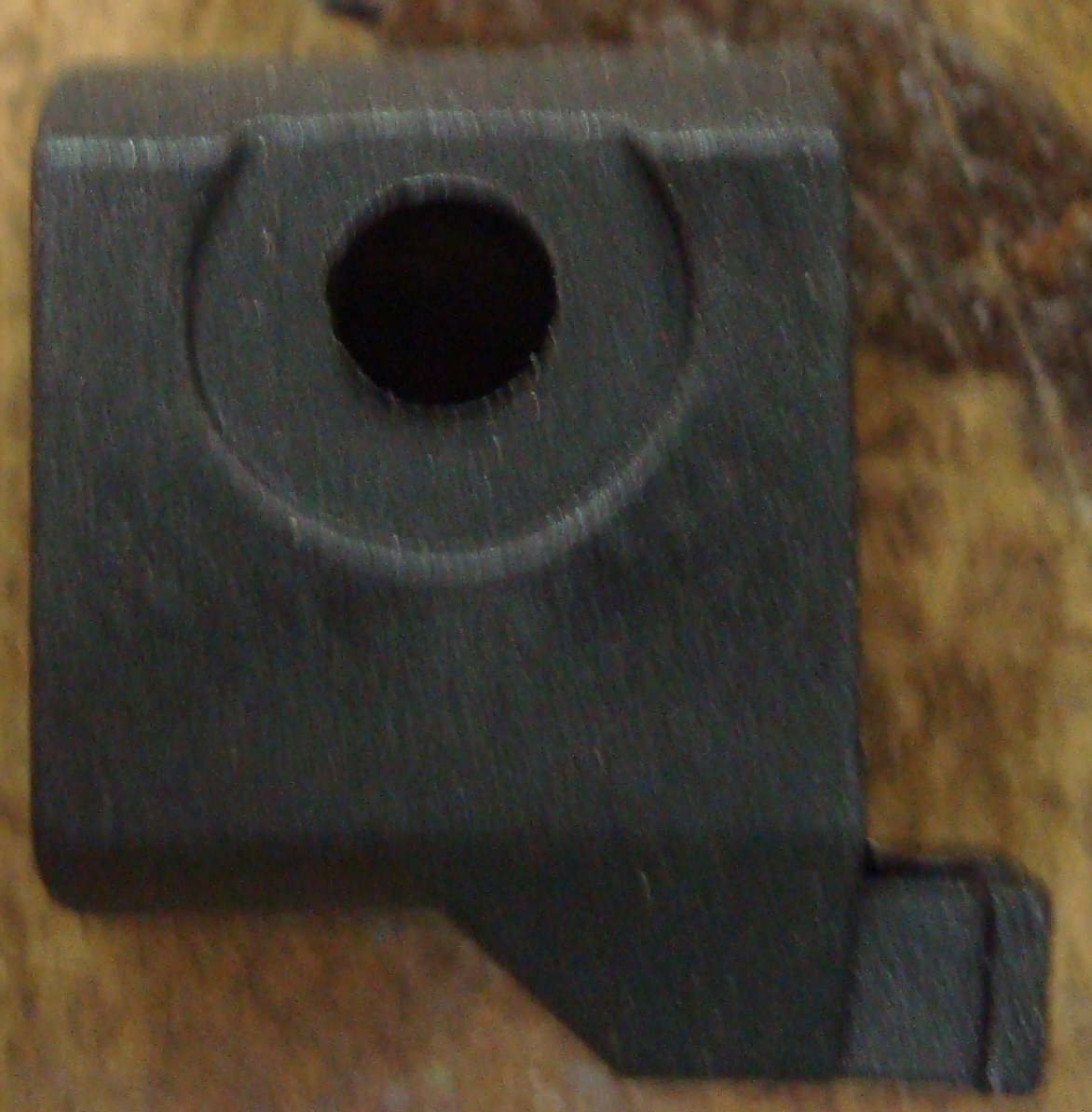
| 12 | Joint 3 | 2 | 5.67 | to attach lamp arm to lamp head and adjust position | stamping | aluminum | Joint 3 |
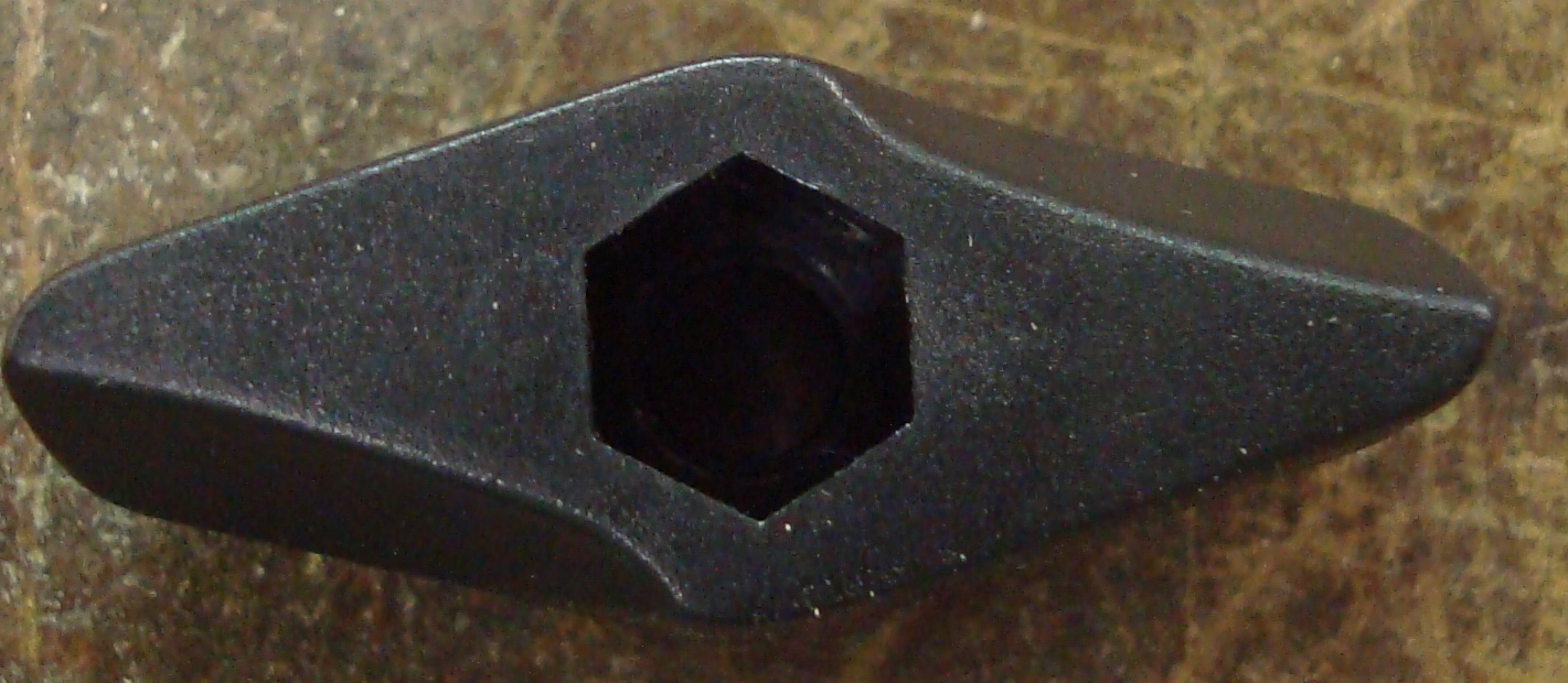
| 13 | Friction Knob | 3 | 2.835 | to tighten joints and hold joints in place | injection molding | plastic | Friction Knob |
| 14 | Friction Knob End Cap | 3 | 0.4706 | to cover ends of screws for friction knobs | injection molding | plastic | Friction Rod End Cap |
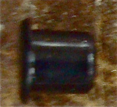
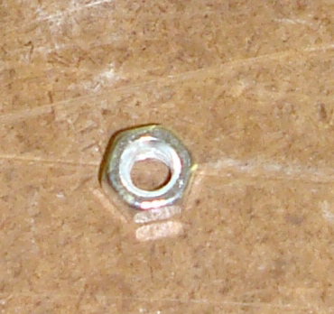
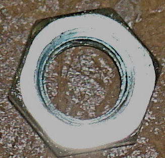
| 15 | Small Nut | 8 | 1.418 | to hold screws in place | pressing, tapping | aluminum | Small Nut |
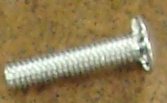
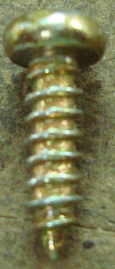
| 16 | Small Screw for Joints 2 & 3 | 5 | 2.835 | to hold joints together | pressing, tapping | aluminum | Small Screw |
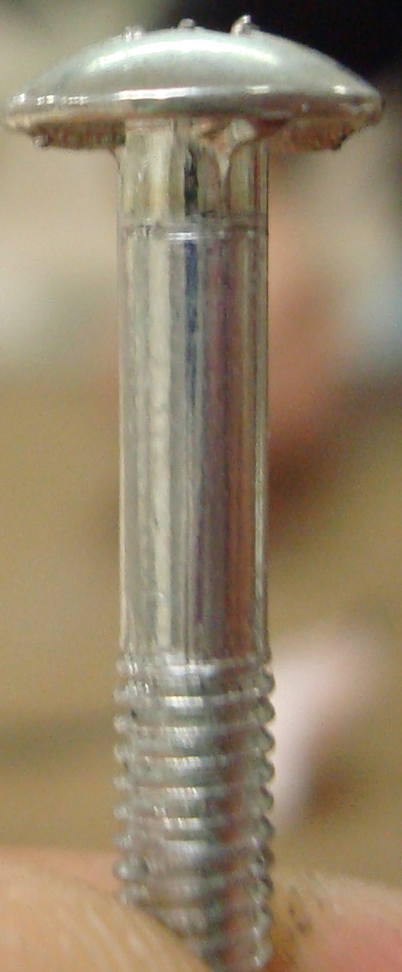
| 17 | Joint 1 Knob Screw | 1 | 2.835 | to hold friction knob in place | pressing, tapping | aluminum | Joint 1 Knob Screw |
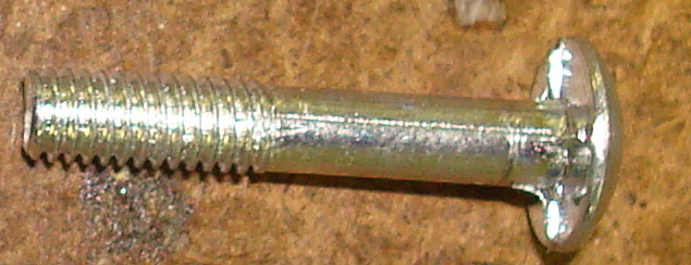
| 18 | Joints 2 & 3 Knob Screw | 2 | 2.835 | to hold friction knob in place | pressing, tapping | aluminum | Joints 2 & 3 Knob Screw |
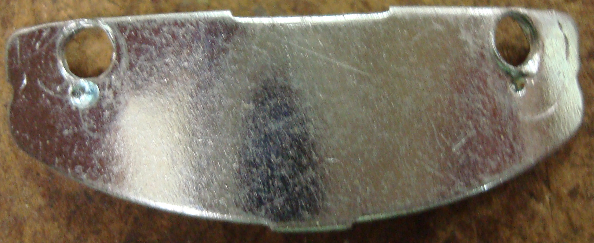
| 19 | Light Bulb Socket Cover | 1 | 53.00 | to guard electronics and hold light switch | stamping | aluminum | Light Bulb Socket Cover |
| 20 | Light Bulb Socket | 1 | 42.00 | to connect lightbulb to lamp and power | stamping, pressing, tapping, saudering | aluminum, copper, ceramics, electrical wires & components | Light Bulb Socket |
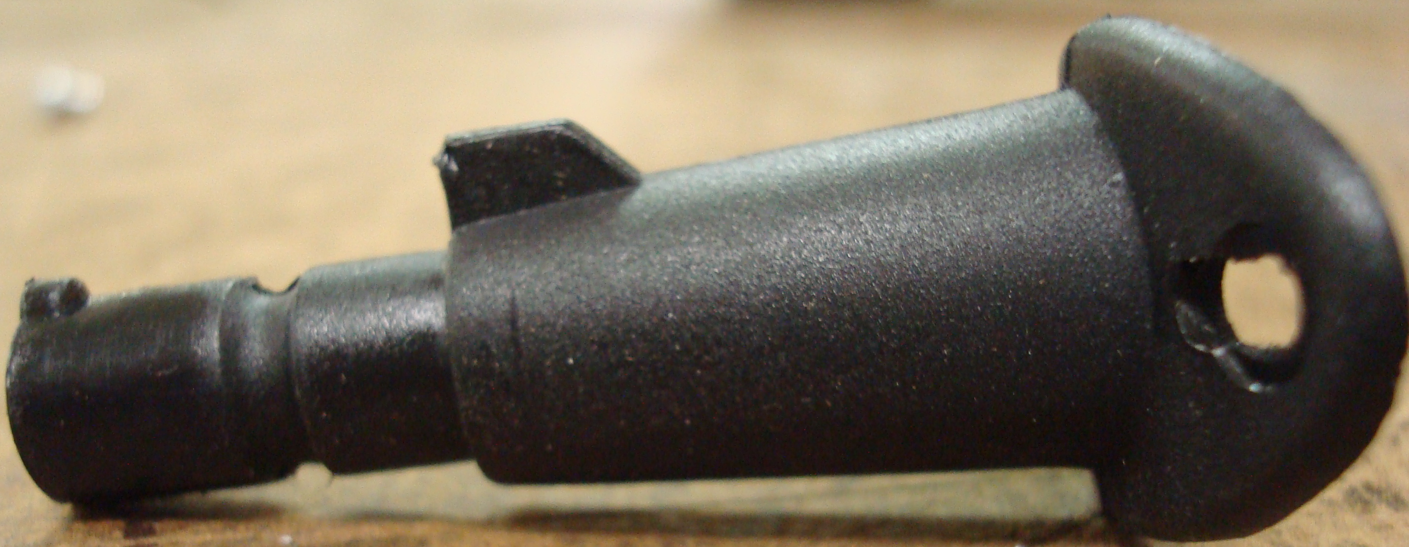
| 21 | Lamp Head Connector | 1 | 5.670 | to connect lamp head to joint 3 | injection molding | plastic | Lamp Head Connector |
| 22 | Lamp Head Connector Screw Holder | 1 | 1.418 | to contain screw that connects to Joint 3 friction knob | injection molding | plastic | Lamp Head Connector Screw Holder |
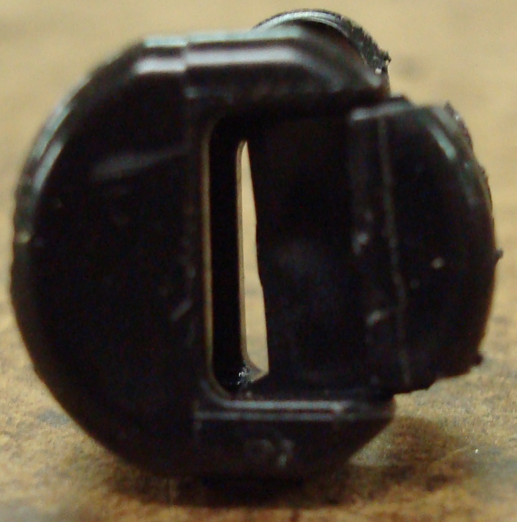
| 23 | Light Switch | 1 | 2.835 | to turn light on and off | injection molding | plastic | Light Switch |
| 24 | Cord Clip | 1 | 1.418 | to connect electric cord to light bulb cover | casting, molding | plastic | Cord Clip |
| 25 | Cord Clip Ring | 1 | <0.01 | to make area around cord clip look nice | injection molding | plastic | Cord Clip Ring |
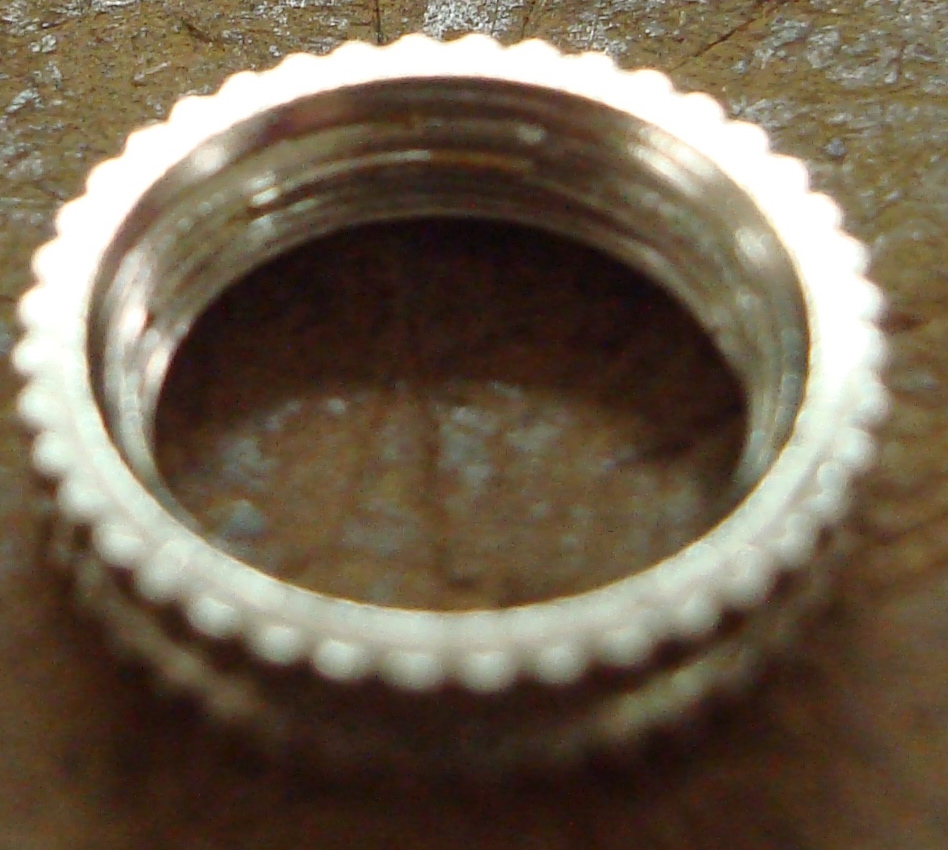
| 26 | Light Switch Ring | 1 | 1.418 | to connect light switch to light bulb cover | extrusion, cutting, tapping | aluminum | Light Switch Ring |
| 27 | Light Switch Connector | 1 | 7.088 | to connect light switch to light bulb socket | extrusion, stamping | aluminum | Light Switch Connector |
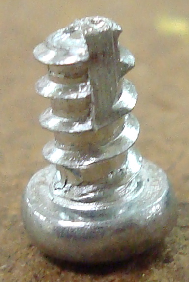
| 28 | Light Switch Connector Screw | 2 | 0.7088 | to hold light switch connector to lightbulb socket | pressing, tapping | aluminum | Light Switch Connector Screw |
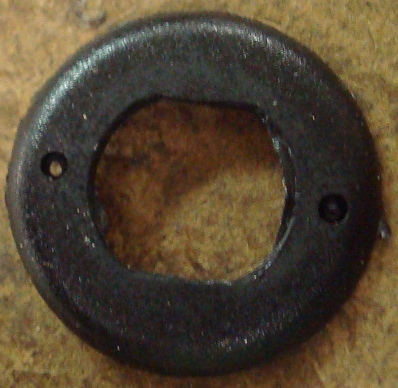
| 29 | Lamp Head Connector Gasket | 1 | 1.418 | to go between lamp head and lamp head connector | cutting, stamping | aluminum | Lamp Head Connector Gasket |
| 30 | Lamp Head Connector Screw | 2 | 0.7088 | to hold lamp head connector to lamp head | pressing, tapping | aluminum | Lamp Head Connector Screw |
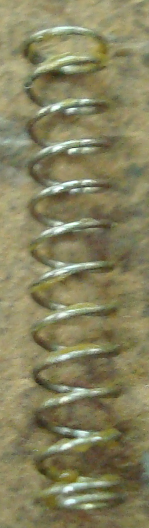
| 31 | Light Switch Spring | 1 | <0.01 | to hold light switch in on/off positions | molding, cutting | brass | Light Switch Spring |
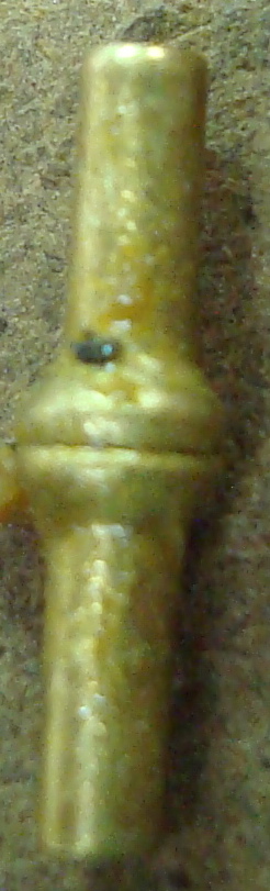
| 32 | Light Switch Spring Pin | 1 | <0.01 | to resist light switch spring | pressing, tapping | brass | Light Switch Spring Pin |
| 33 | Base Clamp Knob | 1 | 1.418 | to adjust distance between base and base clamp | injection molding, tapping | aluminum, plastic | Base Clamp Knob |
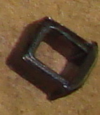
| 34 | Base Clamp Knob Nut | 1 | 2.835 | to thread base clamp knob onto elbow screw | pressing, tapping | aluminum | Base Clamp Knob Nut |
