Table *****: Individual Components of Redesigned Post Hole Digger
| Part Number | Name | Qty. | Weight | Function | Material | Manufacturing Process | Image
|
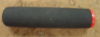
| 1
| Shaft
| 1
| NA oz
| Constrains inner parts of tool and handles physical stresses of digging
| T 6061 Aluminum
| Extrusion
| 
|
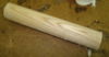
| 2
| Central rod
| 1
| NA oz
| Transmits rotational motion of lead screw into translational motion, forcing shovels closed
| T 6061 Aluminum
| Extrusion
| 
|
| 3
| Crank
| 1
| NA oz
| Turned by user to close shovels
| T 6061 Aluminum
| Extrusion
|
|
| 4
| Shovel
| 2
| NA oz
| Contain dirt when digging
| Steel
| Stamping
| 
|
| 5
| Shaft handle
| 2
| NA oz
| Provides gripping location for ground penetration strike and location for applying counteractive moment to shaft when turning crank to close shovels
| T 6061 Aluminum
| Extrusion
|
|
| 6
| Handle peg
| 4
| NA oz
| Allow user to force tool into the ground using his/her foot
| T 6061 Aluminum
| Extrusion
|
|
| 7
| Guide bushing
| 2
| NA oz
| Constrains central rod to maintain linear motion within shaft
| T 6061 Aluminum
| Extrusion
| 
|
| 8
| Lead screw
| 1
| NA oz
| Transmits rotation of crank into translation of central rod
| Steel
| Automated CNC lathe/threading machine
| 
|
| 9
| Lead screw nut
| 1
| NA oz
| Constrains lead screw
| Brass
| Automated CNC milling
| 
|
| 10
| Lead screw nut bushing
| 1
| NA oz
| Constrains lead screw nut and locates it within shaft
| T 6061 Aluminum
| Lathe???
| 
|
| 11
| Inline ball joint
| 1
| NA oz
| Translates rotation of lead screw to translation of central rod and connects the two parts
| Steel
| ???
| 
|
| 12
| Shovel link
| 2
| NA oz
| Connects central rod to shovels
| T 6061 Aluminum
| Extrusion
| 
|
| 13
| Shovel pivot bolt
| 1
| NA oz
| Joins center of the two shovels, allowing them to pivot about it as a central axis
| Steel
| Upset forging
| 
|
| 14
| Shovel link bolt
| 2
| NA oz
| Joins each respective shovel to its shovel link
| Steel
| Upset forging
|
|
| 15
| Central rod bolt
| 1
| NA oz
| Joins central rod to the two shovel links as a loosely pinned connection
| Steel
| Upset forging
|
|
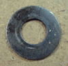
| C10
| M8 washer
| 3
| 0.05 oz
| Increases surface area over which compressive force of the tightened bolt and nut is applied, placed between nut and surface and/or bolt head and surface to prevent damage to surface when nut is tightened
| Steel
| Stamping
| 
|
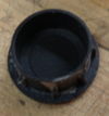
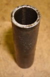
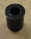
| C11
| Bushing
| 1
| 0.7 oz
| Used to align two Connecting arms and create a low friction surface for Connecting arms to pivot about
| Brass
| Roll forming
| 
|
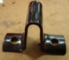
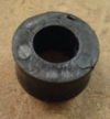
| C12
| Plastic spacer
| 1
| 0.05 oz
| Placed concentric with Bushing between two connecting arms to provide low friction surface and prevent the arms from wearing against one another
| Plastic
| Injection molding
| 
|
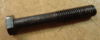
| C12
| Scissor pin bolt
| 1
| 0.3 oz
| Joins two handle assemblies together, passes though Bushing to create main joint around which handles pivot
| Steel
| Upset forging
| 
|
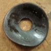
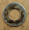
| C13
| M10 washer
| 1
| 0.1 oz
| Increases surface area over which compressive force of the tightened bolt and nut is applied, placed between nut and surface and/or bolt head and surface to prevent damage to surface when nut is tightened
| Steel
| Stamping
| 
|
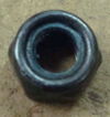
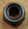
| C14
| M10 lock nut with nylon insert
| 1
| 1.3 oz
| Threads onto scissor pin bolt and tightened to join connecting arms together. Nylon insert prevents nut from loosening
| Steel
| Forging
| 
|
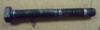
| C17
| Digging head pivot bolt
| 1
| 0.8 oz
| Connects two digging heads together, creates pivot point around which digging heads open and close
| Steel
| Upset forging
| 
|
| C18
| Large plastic spacer
| 2
| 0.1 oz
| Placed on pivot bolt to align two digging heads and protect pivot bolt
| Plastic
| Injection molding
| 
|
| C19
| Small plastic spacer
| 1
| 0.05 oz
| Placed on pivot bolt to align two digging heads and protect pivot bolt
| Plastic
| Injection molding
| 
|


