Lead-screw post hole digger
From DDL Wiki
Contents |
List of Parts
Quality Function Deployment
Insert QFD here
Mechanical Analysis
Include both new and old Mechanical Analysis.
Our mechanical analysis of our product was carried out in two main phases. The goal of our first analysis was to optimize the design of our post hole digger by determining an appropriate lead screw design to purchase and then use in the development of our product. The result of this analysis was a set of parameters describing our ideal lead screw, and the acquisition of a screw that most closely matched these parameters for use in our prototypes. Our second analysis focused mainly on the durability associated with our product and whether or not the design would be sufficiently strong to withstand the rigors of post hole digger use. We concluded that all of the components of our design had high factors of safety and would thus be suitable for their intended use.
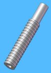
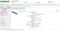
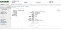
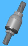
Our first analysis was submitted to the client in early November, and can be viewed in pdf from here. As stated above, the main result of this analysis was the selection of the lead screw design shown on the right in Figure --. Our second analysis was completed recently and is presented in its entirety here.
Determination of Lead Screw Stress
The first step in our second analysis was to determine the stress on the threads of our lead screw when the post hole digger impacts the ground. When a user drives any post hole digger into the ground, they do so with a significant amount of force as they wish to penetrate the earth as much as possible. This results in a fairly large force being incident on the open heads of our post hole digger, which travels up the shaft of the digger and is incident upon the lead screw. If this force is large enough or the lead screw not strong enough, the threads of the screw could be damaged, possibly rendering the digger unusable. In order to determine this stress on the threads of the lead screw, two pieces of information were required: the incident force on the lead screw, and the area of the threads of the lead screw.
Determining the incident force upon the lead screw was fairly straightforward. In our first mechanical analysis, we performed the preliminary part of this analysis by looking at what percentage of a vertical force incident on the digging heads was transmitted up to the shaft of the digger; we referred to this as the transmissibility ratio of the digger. The design in its current state had a transmissibility ratio of 1.21, meaning that for every one pound of force incident on the digging head, 1.21 pounds of force would be transmitted to the shaft. As the actual amount of force incident upon the heads is difficult to measure empirically, an estimate of the force was required. We placed an upper bound of 150 pounds on the impact force, but for the purpose of this analysis we will extend this to 200 pounds incident on the heads. This results in a 242 pound force on the threads of the lead screw using our transmissibility ratio.
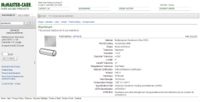
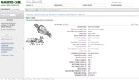
Calculating the area of the lead screw heads is a fairly simple geometric calculation. If unraveled from the screw itself, the threads will resemble a rectangle with a height equal to their one half of the pitch of the screw and a length of the circumference of the thread around the screw. The height of this rectangle can be determined from information provided by McMaster-Carr (the supplier of this screw) and from the book 'Design of Mechanical Elements' by -, shown together in Figure -- on the left. As the two indicate, the height of our rectangle is equal to one half of the pitch of the screw. As our screw has 8 turns per inch, it has a pitch of one-eighth of an inch and a height of one-sixteenth of an inch. The length of this rectangle can be calculated from a simple trigonometric calculation shown in Figure -- on the left, where d is the diameter of the screw and φ is the lead angle of the screw. Finally, as there are 8 separate threads, the total area must be multiplied by 8. The total are of the threads is thus:
assumptions
Mechanical Analysis: Your quantitative mechanical analysis (and any relevant mechanical testing) will be evaluated on the following criteria:
 Is the purpose of the analysis clearly stated? How does the result help to understand the design or justify design choices?
  Is the analysis at a reasonable level of complexity? An extremely difficult analysis is unwarranted at this stage, but the analysis should be sufficient to provide some new information, not just something obvious.
  Are assumptions clearly stated, and are they appropriate?
  Are all symbols and all steps in the analysis clearly defined? (Often this will require a picture to show where the parameters appear in the product). Is the analysis fully defined such that another engineer could reproduce the results given only the documentation?
  Is the conclusion from the analysis clearly stated? (e.g.: if the analysis calculates a required force of 5.0N, is this good? bad? Does it imply other requirements? What does it mean, and why should the client care?)
