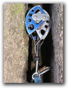
Active climbing cam
From DDL Wiki
Contents |
Pre-Dissasembly Phase
User interaction
Inputs
- retraction force from hand
- friction force from rock
- reaction force from rock
Outputs
- force on climbing rope
- force on rock
Function
Spring Loaded Camming Devices
- protect against falls in free or aid climbing
- build removable anchors in rock
- secure a belayer
- mountaineering uses
- mountain rescue
- passive climbing protection
Method of Use
- locate crack
- Identify appropriate size cam unit
- remove cam from harness/chest sling
- grip cam securely
- retract the trigger
- insert in crack, pocket or flake
- find secure placement
- orient the cam with expected direction of force
- retract trigger and remove
- removed either on rappel or by 2nd climber
- replace back on harness or chest sling
Stakeholders
- climber
- rescue workers (mountain rescue)
- insurance companies (health, life & company insurance)
- tourism
- manufacturers
- hospitals
- environment
- retail services
- distributors
Issues associated with use
- having proper size for each type of placement
- dropping the device while climbing
- "walking" in cracks (when device gets stuck in a rock and you cannot remove it)
- with many devices the extra weight is evident
Watch a demonstration video on using a climbing cam that we did in the lab
Part analysis
Manufacture of parts
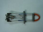
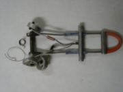
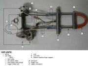
The climbing cam is a mechanical device composed of 12 different parts.
| Part No. | Name | Weight (g) | Qty. | Function | Manufacture method |
|---|---|---|---|---|---|
| 1 | spring | 0.5 | 2 | ||
| 2 | cam lobes | 7 | 3 | ||
| BODY | 45 | 1 | |||
| 3 | thick cable | 1 | |||
| 4 | thin plastic tubes | 2 | |||
| 5 | sling; plastic tube (orange) | 1 | |||
| 6 | trigger | 1 | |||
| 7 | axle | 1 | |||
| 8 | axle ends | 2 | |||
| 9 | finger support | 1 | |||
| 10 | spring pin | 3 | |||
| 11 | trigger wire | 3 | |||
| 12 | copper connector | 3 | |||
| TOTAL | 52.5 | 24 |
Functionality
On its initial position, the camming device starts with the three lobes aligned horizontally. The trigger is pulled towards the sling using the index and middle finger. This movement slides the trigger down pulling the trigger wires, which are attached to the trigger on one end, and to the lobes on the other end. The tension on the cables causes the lobes to rotate around the axle; the trigger must be pulled until the lobes are completely aligned vertically. During the triggering process, the springs come into action, creating an opposite force that causes the lobes to resist to rotation (and at the same time trying to bring the lobes back to their initial position); the fingers in the trigger must therefore apply resistance to keep the lobes aligned vertically. At this time is when the cam is inserted in the crack. Once the cam is in place, the trigger must be released, causing the lobes to return to their normal position. Now, the springs are in charge of pushing the lobes against the rock walls inside the crack.
Failure analysis
The climbing cam relies mostly on the correct functionality of the lobes, which are the parts in contact with the rock while the device is in place. The lobes rest on the axle and the springs give them the force keeping them against the rock walls. Additionally, during climbing more than one cam is used. In case of any single one cam failing, the remaining cams will support the climber(s) from falling.
Customer Needs/Product Requirements
-reliable in a fall
-light weight
-easy and versatile placement
-low cost for user group
-durable and long lasting, able to withstand use in the mountains
-easy to handle
-diverse functionality
-compatible with sizes of older models
-accomdates variety of hand sizes
-intuitive for new users
-easy to retrieve from rock
-fast placement and removal


