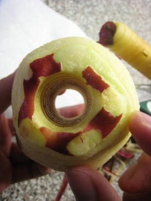
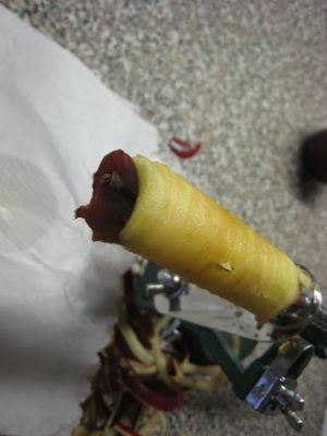
Apple peeler
From DDL Wiki
Contents |
Executive Summary
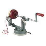
In this report we tested and analyzed a mechanical apple peeler through different aspects and we believe that there are a lot of potential improvements on this product.
After performing a usability test on the product we found out several major problems of the product. First of all, in order to remove the corer/slicer blade the user would have to unfasten a butterfly nut which is located right next to the blade. There is a large possibility of getting cut by the blade while doing so. On the other hand, the apple has to be attached to the tri-fork in the proper orientation in order for the peeler to operate smoothly. We also found out that the suction base has a large failure rate when operating on a rough surface.
We then dissected the product, took every component apart, and studied each part. The Failure Modes and Effects Analysis shows that the springs, the vacuum base, and the channel stopper has the greatest Risk Priority Number among all the parts. It is crucial to look further into improving the performance or durability of these parts.
In our Design for Manufacturing and Assembly analysis we recognized that the screws and nuts are not standardized. This problem is further amplified as most of the assembling procedure is done by human. Most of the parts are made using standard manufacturing methods such as casting, punching, thread rolling, and injection molding. Some components, however, require a second procedure such as nickel-plating to prevent rusting of the part. In our Design for Environment analysis we found out that the primary environmental concern of the product is its carbon dioxide emission.
Lastly, we performed a Mechanical Analysis on the product to investigate its performance using mathematical functions and physics relations. We simulated various magnitudes of torque acting on the handle and calculated the maximum torque the suction base can withstand before it fails. Through the study we found out that the suction base is sufficient to withstand torques and forces under normal usage.
Customer Needs
The primary customer need in an Apple Peeler is to have the ability to easily and quickly remove the skin of an apple. This means that the user must be able to peel the apple without exerting more force or energy or spending more time than they would when peeling with a hand-held peeler. It is also expected that the device can peel the skin off various types of fruits and vegetables of similar shape and size. Since this is an everyday kitchen ware, the first and foremost requirement for this product is ease of use and safety. If must be easy enough so that the device can be operated from common sense without instruction by people of different age groups. It must be safe to be used by small children and elders, both male and female. Customers should not have to worry about possible safety hazards caused by everyday equipment.
Stakeholders
The following are the major stakeholders which influence the new design of an Apple Peeler.
Consumers
The consumers are the primary stakeholders of the product. The “consumer” maybe anyone from any age group of any gender since it is an everyday kitchen ware.
- Product must be relatively cheap to purchase since the function of the product is limited as opposed to a table knife.
- Safety must be considered in detail to prevent any type of injuries.
- Design will need to accommodate various users with different sizes and strength.
- Operation of the product must be intuitive to be carried out without instruction. One or two step process is preferred.
- Product must efficiently and quickly skin the apple.
- Product must be able to skin apples of all sizes and shapes.
- Must be easy to maintain. i.e. Easy to clean and no rusting.
- Easy to store, Easy to setup.
- Must be robust. Should be able to work on various surfaces and with various products.
- Aesthetics must be appropriate for a kitchen.
Retailers
Retailers are concerned with how the product presents itself at their stores.
- Product must be compact as possible for efficient storage.
- Product must be of manageable weight to be handled easily at stores.
- Product must be durable enough to stay intact even when handled poorly or dropped.
- Product should be aesthetically pleasing or should be able to be made aesthetically pleasing to attract customers.
Manufacturers
Manufacturers are concerned with ease manufacturing.
- Product should have low part count.
- Parts used should be easily accessible. This may mean that the parts have already been manufactured for other products.
- Material used in manufacturing the parts should be cheap and easily accessible.
- Assembly process should be simple, quick and easy to reduce production speed and labor costs.
Shipping/Transport
The primary concern in shipping is to deliver product received by manufacturer to retailers in a timely manner without any variation in product quality.
- Product must be easy to handle. This may be done by reducing weight and choosing appropriate shape of the product so that when the product is boxed it is easy to handle.
- Product must be durable so that any external load applied during shipping does not affect the quality of the product.
System Function
Function to be performed
The Apple Peeler can have the following functions:
- 1. Peel an apple
- a. The corer/slicer is removed and handle is turned.
- 2. Peel, core and slice and apple
- a. In addition to the peeling process above, the apple is cored and sliced in a spiral.
- 3. Core and slice and apple
- a. Same function as above but without peeling the apple.
- 4. Suction cup fixes the base to the table top
- a. The lever activates the suction cup which applies a downward force on the product, giving the user support when peeling the apple.
Operation Steps
To operate the device, the following steps are followed.
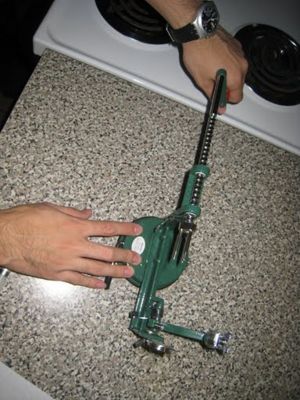
- 1. Place the device on a smooth surface, making sure there is no irregularity on the surface or dust which may reduce the effectiveness of the suction cup.
- 2. Turn the suction cup lever to activate the suction cup. Check that the device is securely attached to the surface.
- 3. Pull the handle away from the device as much as possible to allow enough space for the apple to be placed within the device.
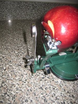
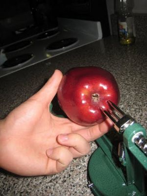
- 4. Secure the apple in the device by pushing the bottom of the apple into the tri-fork.
- 5. Depending on the functions the user wish to perform, follow one of the following;
- a. Function 1:
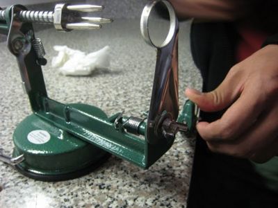
- i. If the corer/slicer is attached, remove it by loosening the butterfly nut.
- a. Function 1:
- ii. Place the peeler blade to come in contact with the apple surface.
- b. Function 2:
- i. If the corer/slicer is not attached, attach it by tightening the butterfly nut.
- ii. Place the peeler blade to come in contact with the apple surface as seen in section above.
- b. Function 2:
- c. Function 3:
- i. If the corer/slicer is not attached, attach it by tightening the butterfly nut.
- ii. Move the peeler blade away from the apple surface until the peeler handle stopper clicks into place.
- c. Function 3:
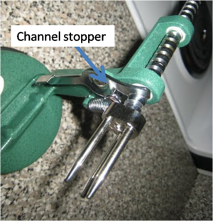
- 6. Make sure the channel stopper is on the groove of the grooved channel.
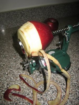
- 7. Turn the handle away from the body until sufficient result is achieved according to the user.
- 8. Remove the apple from the device.
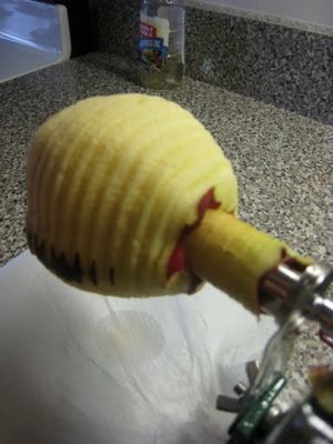
- 9. Remove the core from the tri-fork by slowly reversing the direction of the turn.
Usability
The following feedback was given from the user who operated the device in a typical use scenario, which are;
- In a kitchen.
- On smooth tiled kitchen top.
- With an apple of standard size and shapes.
- By an average male.
Handle
- Handle screw becomes loose after several runs.
Suction cup
- Suction cup lever should be on the other/both side. The user is required to reach over the device in order to activate the suction cup, which is a potential safety hazard.
- Strength of suction is not enough to support the peeling process. User is required to hold the base even when the suction cup is activated.
Peeler
- Uneven apple surface causes the peeler to miss the part of the skin, leaving some areas unpeeled.
- The blade will wear after time, and there are no replacement blades. This means the customers are forced to buy a new product when the blade becomes dull.
Corer/Slicer
- Friction from nut and bolt is the only support of the corer/slicer and therefore this nut and bolt is very tight. Significant force was required to tighten/loosen the assembly by an adult male.
- Slicing and coring are performed by the same part, so both functions must be performed at the same time. The user has no freedom to choose one from the other.
- The nut which hold the corer/slicer is very close to the blade and may cause injury when trying to remove the nut.
- Adjustment of the corer/slicer requires the use of screw driver, which is too time consuming and troublesome when more than one apple are peeled in several different ways.
- The blade back/front is not clear and therefore user may attach the corer/slicer in the wrong orientation. The device would fail to operate its intended function, and may break the device.
Tri-fork
- Apple placement requires strength. Some elders and children will require assistance when operating the device.
- Apple core is hard to remove after coring and causes the core to shoot off the tri-fork.
- The apple must be placed in the correct orientation, or it will not peel and also potentially break the product.
General
- The peeled skin made a mess on the kitchen table and product.
- Troublesome to re-place the groove locker after each peel.
- The adjustments are done by screwing and unscrewing nuts and bolts, which is very troublesome.
- The nuts keep the majority of the parts intact and therefore very tight and hard to remove.
- There is no replacement for the nuts. User may try to remove the slicer blade and if a nut is lost during this process, the peeler is no longer functional.
- The peeling process must be done in one continuous run. Once stopped, the peeler may not peel some areas of the apple.
- The size of the peeled object cannot exceed the specification. The product has very little robustness.
- The product is very hard to clean after covered in apple skin and juice due to its difficulty in dis-assembly.
Product Assembly
List of Parts
Assembly Diagrams
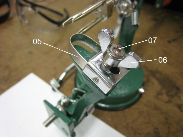
| U-shape peeler assembly |
|---|
|
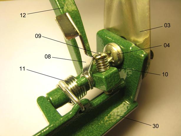
| Peeler handle and stopper assembly |
|
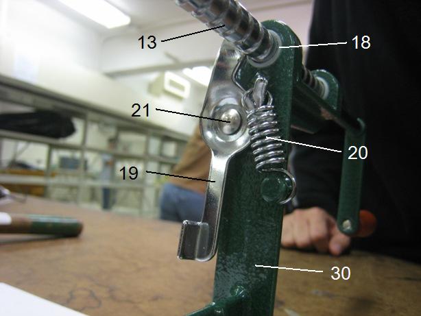
| Grooved channel and channel stopper assembly |
|
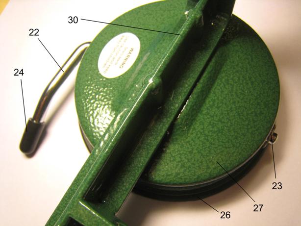
| Vacuum base assembly |
|
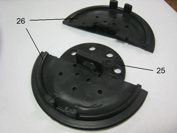
| Rubber casing and hard rubber assembly (dissected) |
|
Failure Modes and Effects Analysis
As seen from the table below, the failure modes which exhibit a high RPN is due to general wear which is experienced by any product made from any material. This means that the parts with high RPN will need a complete redesign to improve its functionality and reliability. Although some components have a high RPN, the failure will only result in damage to the device and not to the user. It is very unlikely that the user will experience life threatening injuries as a result of one of the failure modes listed below, thus the improvement on the failure modes are to increase robustness and product life span rather than decreasing user risk.
Judging from the table the appropriate improvement method is to redesign small parts of the assembly, such as replacing the butterfly nut with more reliable fastening component which does not rely on friction to keep the component intact. Since 15 out of 25 failure modes require redesign or alternative solution, this product can definitely be improved in this way to increase customer satisfaction.
The highest RPN is exhibited by loosening of the torsional spring. This would mean that this part will need change to increase the quality of the product. However, it will be much more satisfactory for the users if minor FMEA factors such as maintainability was improved.
| Part Number | Item & Function | Failure Mode | Effects of Failure | S | Causes of Failure | O | Design Controls | D | RPN | Recommended Actions | Responsibility & Deadline | Actions Taken | S | O | D | RPN |
|---|---|---|---|---|---|---|---|---|---|---|---|---|---|---|---|---|
| 3 | Corer/slicer blade | Blunt, bending | Operation impaired | 7 | Extended use | 7 | Durability test | 1 | 49 | Better material | Materials Engineer | - | - | - | - | - |
| 3 | Corer/slicer blade | Loosened | Unstable operation | 7 | Lack of user maintenance | 6 | Fleet test | 2 | 84 | Alternative solution | Mechanical Engineer | - | - | - | - | - |
| 5 | U-shape peeler | Blunt | Operation impaired | 7 | Extended use | 7 | Durability test | 1 | 49 | Better material | Materials Engineer | - | - | - | - | - |
| 5 | U-shape peeler | Failure | Incomplete peeling | 3 | Lack of robustness | 7 | Fleet Test | 1 | 21 | Better design | Mechanical Engineer | - | - | - | - | - |
| 8 | Peeler handle stopper | Deformed | Not able to disable peeler | 5 | Fatigue | 4 | Durability test | 2 | 40 | Reinforcement, thicker metal | Mechanical Engineer | - | - | - | - | - |
| 11 | Torsion spring (peeler handle) | Loosened | Not able to peel | 8 | Extended use | 4 | Lifetime test | 6 | 192 | Alternative solutions | Mechanical Engineer | - | - | - | - | - |
| 12 | Peeler handle | Deformed | Operation impaired | 7 | Fatigue | 2 | Lifetime test | 2 | 28 | Reinforcement | Mechanical Engineer | - | - | - | - | - |
| 13 | Grooved channel | Cracked groove | Rough operation | 7 | Wear | 3 | Fleet test | 3 | 63 | Better material | Materials Engineer | - | - | - | - | - |
| 14 | Tri-fork | Deformed, loosened | Unstable operation | 6 | Excessive force from user, fatigue | 5 | Fleet test | 4 | 120 | Redesign structure | Mechanical Engineer | - | - | - | - | - |
| 14 | Tri-fork | Incorrect object orientation | Incomplete peeling | 7 | Wrong user input | 3 | User test | 3 | 63 | Alternative solution | Mechanical Engineer | - | - | - | - | - |
| 15 | Screw(for wooden handle) | Loosened | Handle detached | 6 | Extended Use | 8 | Lifetime test | 2 | 96 | Redesign Structure | Mechanical Engineer | - | - | - | - | - |
| 16 | Wooden handle | Cracked | Rough operation, might injure user | 5 | Wear, corrosion | 5 | Lifetime test | 3 | 75 | Better material | Materials Engineer | - | - | - | - | - |
| 17 | Handle lever | Deformed | Erratic operation | 2 | Fatigue | 2 | Durability test | 3 | 12 | Reinforcement | Mechanical Engineer | - | - | - | - | - |
| 18 | Plastic ring | Cracked | Unstable operation | 4 | Wear | 3 | Durability test | 7 | 84 | Better material | Materials Engineer | - | - | - | - | - |
| 19 | Channel stopper | Deformed | Operation impaired | 7 | Wear, fatigue | 4 | Lifetime test | 5 | 140 | Reinforcement, thicker metal | Mechanical Engineer, Materials Engineer | - | - | - | - | - |
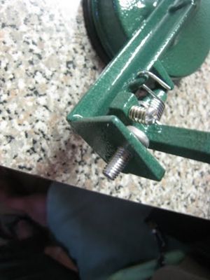
| 20 | Extension spring (channel stopper) | Loosened | Operation impaired | 7 | Wear | 4 | Lifetime test | 6 | 168 | Alternative solutions | Mechanical Engineer | - | - | - | - | - |
| 21 | Channel stopper rivet | Cracked, loosened | Unstable operation | 5 | Wear, fatigue | 2 | Fleet test | 7 | 70 | Alternative solutions | Mechanical Engineer | - | - | - | - | - |
| 22 - 26 | Vacuum base | Suction base detached from surface | Operation impaired | 7 | Excessive force from user | 3 | Dynamics test | 1 | 21 | Alternative solution/Redesign base | Mechanical Engineer | - | - | - | - | - |
| 22 - 26 | Vacuum base | Losing suction | Vacuum inoperative | 7 | Wear | 6 | Fleet test | 4 | 168 | Reinforcement/Alternative material | Mechanical Engineer, Materials Engineer | - | - | - | - | - |
| 22 - 26 | Vacuum base | No suction | Vacuum inoperative | 7 | Rough surface | 4 | Surface test | 1 | 28 | Alternative solution | Mechanical Engineer | - | - | - | - | - |
| 27 | Base case | Deformed | Poor appearance | 3 | Fatigue | 3 | Durability test | 2 | 18 | Reinforcement | Mechanical Engineer | - | - | - | - | - |
| 30 | Main body | Deformed | Unstable operation | 4 | Fatigue | 2 | Durability test | 2 | 16 | Reinforcement | Mechanical Engineer | - | - | - | - | - |
| 30 | Main body | Failure | Operation impaired | 4 | Lack of robustness | 2 | User test | 2 | 16 | Redesign | Mechanical Engineer | - | - | - | - | - |
| 30 | Main body | Maintenance failure | Hindered cleanliness | 2 | Lack of maintenance | 2 | User test | 3 | 12 | Redesign | Mechanical Engineer | - | - | - | - | - |
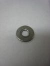
| 1, 2, 4, 6, 7, 9, 10, 15, 28, 29 | Butterfly nuts, washers, screws | Loosened, threads stripped | Rough, unstable | 3 | Wear | 4 | Lifetime test | 7 | 84 | Better material, alternative solutions | Materials Engineer, Materials Engineer | - | - | - | - | - |
The study shows that the torsion spring, the extension spring, the vacuum base, and the channel stopper has the greatest RPN number among all the parts. The torsion and the extension springs (each with RPN greater than 150) are crucial components of the assembly and would cause the product to lose its primary function if they fails. The vacuum base, on the other hand, also has a high RPN because it will lead to great inconvenience of the user if failed and it is not easy for the user to detect when it starts wearing down. The channel stopper also has a high RPN because its function is directly related to the proper operation of the product. This table helps us to better analysis each individual parts and the risk bear by the user and other stakeholders. It is crucial to look further into improving the performance or durability of the parts with high PRNs.
Design for Manufacturing and Assembly
DFMA is a set of guidelines that allows engineers and designer to reduce the complexity and cost of manufacture of a product.
Apple Peeler DFM
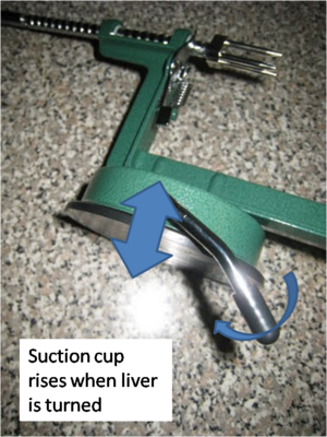
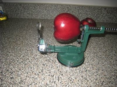
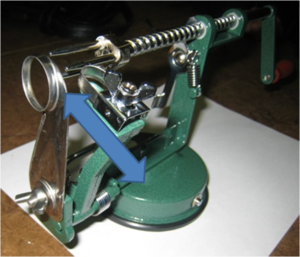
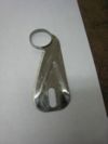
The apple peeler exhibits good DFMA, it is simple and functional with few parts. When examining and dissecting our products, we divided the product into 6 major components: the corer/slicer, the peeler, the grooved channel, the main body, the base, and the suction cup. First of all, the corer/slicer is made of stainless steel and is made through stamping stock into the desired shape. The design of the corer/slicer is developed so that the appropriate size of the core can be extruded while the apple goes through. The u-shaped peeler is also made of stainless steel and is made by stamping. The peeler handle is connected to a spring so that it can adjust the u-shaped peeler into the best position with appropriate force exerting on the apple. Moreover, the grooved channel is made of Nickel-plated Carbon Steel and is made by extrusion. The tri-fork that holds the apple is connected to the very front of the grooved channel. As we spin the handle, the tri-fork that hold the apple would gradually rotate and move toward the u-shaped peeler. The main body and the base are both made of steel and are made by casting. The last component is the suction cup. The suction cup is made of rubber and is made by injection molding. One thing should be noticed here is that the vacuum rubber case contains a hard rubber plate with 10 equally space holes, as we rotate the vacuum lever, the hard rubber plate would rise up and thus provide suction on the surface. They did surface treating on the rubber case so that the surface is smooth, the apple peeler can thus effectively stay firmly. Furthermore, the peeler handle, the main body, and the base would be painted. Since these three parts are made of Aluminum, painting is a necessary operation to prevent metal from rusting.
Apple Peeler DFA
The way the apple peeler is assembled is by pre-manufactured fasteners, which increases the ease of assembly. The fasteners used in this design, however, have different thread size on different parts, which would increase the difficulty of assembly. The apple peeler actually includes 30 components. Even though we only mentioned six main parts here, the actual manufacturing process is indeed long and time consuming due to the large numbers of components assembly. For the future design, standardizing different kinds of fasteners and reducing the numbers of trivial components would definitely be our goals.
Design For Environment
Society has growing awareness of businesses effects on the environment. Emission reduction became one of the major issue for manufacturing industry. From raw material aquisition, manufacturing stage, to merchandise distribution, each phase releases greenhouse gas undermining the atmosphere. Meanwhile maintaining the product quality while continuing to regulate emissions is also very important.
EIO-LCA:
For engineers to assess the consequence of a product on the environment, The Economic Input-Output Life Cycle Assessment (EIO-LCA) method is developed under Green Design Institute of CMU. EIO-LCA method estimates the environmental impact of a product by examining its contribution to other economic sectors throughout the product life span. EIO–LCA method also help us prioritize the most important phase by showing the major economic sectors that involves in the product life cycle.
Economic Activity
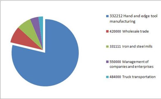
After researching all the sectors again, we found that #332212 Hand and edge tool manufacturing is a better sector representative of apple peeler than the original sector, #335221: Household cooking appliance manufacturing, because under sector #335221, most activities are such as ovens and stoves manufacturing, and because sector #332212 has a lot similar activities such as Can openers, Axes manufacturing, Forks manufacturing, which some of them are the exact same components on our apple peeler.
The data shows every additional $1 million dollar going into stimulates a total of $1.97 million in all sectors combined.
Note that apple peeler is a low tech product, so by EIO-LCA tool we see most economic flux goes into material supplier and business spending.
Much investments go into distributing and resell the product, therfore the wholesale Trade sector gains 0.102 million as the second beneficiary sector.
Iron & Steel Mills gains 0.088 million.
Greenhouse gas pollution
Apple peeler GHG
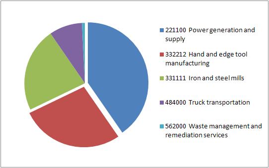
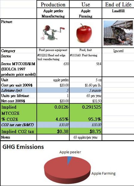
From the table, we see for every $1 million into the household cooking appliance manufacturing, 630 metric tons of CO2 greenhouse gas is emitted. And Most of the greenhouse gas is caused evenly by power generation and supply, Hand and edge tool manufacturing, and iron/steel mill production. A typical apple peeler cost from $10 to $30, average $20. Our calculation shows us that 0.0126 MTCO2E(Metric tons) is produced for each apple peeler.
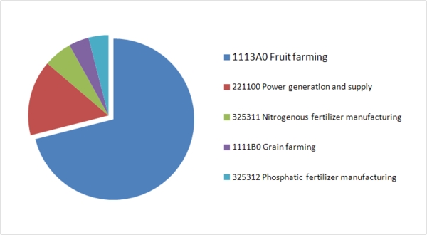
Apple GHG
In addition, an apple peeler needs to be used with apple.
A average person in United States eat 65 apples a year.
one pound of apple costs about $1.60 dollar, and an average apple in supermarket is about 5 oz.
Therefore one apple is about $0.50 dollar. The implied CO2 is 0.0004485 MTCO2E per apple.
Assume 65 apples per year, the CO2 emission would be 0.291525.
CO2 Taxes
The C02 taxes shows that the process of manufacturing an apple peeler causes only 0.38/8.75 = 4.3% of the total CO2 produced by growing 65 apples for one year diet.
Toxic releases
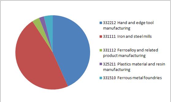
The table shows that amount of toxic release into the environment.
Most toxic release for manufacturing apple peelers is caused by Iron and steel mills (raw material & manufacturing parts).

![]()
Raw Material Acquisition: Pollution generated in order to make raw steel and iron.
Transportation: fossil fuel
Manufacture: most pollution is generated in order to produce energy for forging/casting the steel parts.
Distribution: fossil fuel
User: an apple peeler is purely mechanical, pollution is zero.
End of Life/Disposal: steel is a recyclable material.
Conclusion:
We conclude that an apple peeler should have minimal impact to the environment based on its life cycle.
However, because most pollution occurs when acquiring the material or manufacturing the parts,
and also because we have no ability to limit people from eat apple as many as they want,
so we will be working toward reducing the number of parts or total volume of the whole assembly.
Mechanical Analysis
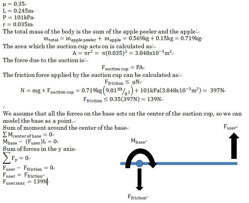
The mechanical analyses for the apple peeler is intended to find the maximum force one can apply to the handle bar without moving the apple peeler. Before the calculation, the assumptions used include the following:
- Completely vacuum condition within the suction cup
- The distance between the surface and the highest point of suction cup surface is small compare with the diameter of the suction cup
- Center of mass of the apple peeler is approximately 0.01m away from the right edge of suction cup
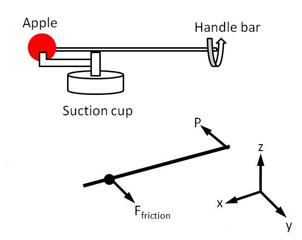
If we assume the suction cup as a single point, we can then draw our FBD as shown below.
Let’s clarify all the symbols first μ is the friction coefficient; N is the normal force perpendicular to the contact surface; L is the length between the suction cut and where the force is applied; P is the atmospheric pressure at 1 atm; r is the radius of the suction cup; A is the area of the suction cup where the atmospheric pressure exerting to. Here we use the average mass of apple as mapple , which we found as 0.15 kg, and we found that the friction coefficient between rubber and ceramics is 0.35. (Appendix A)
Analysis Conclusion: The maximum force that one can exert before moving the apple peeler is roughly 140N. The calculation results have shown us that the product would not move easily under the applied conditions and assumptions. This is sufficiently large to peel an apple quickly and safely since the maximum force required to peel an apple was measured to be 40N using a Newton meter, and in many cases it is much less.
Analysis Conclusion: The maximum force that one can exert before moving the apple peeler is 40N in case 1, 112N in case 2, 88N in case 3.The calculation results have shown us that the product would not move easily under the applied conditions and assumptions.
Since the minimum Pmax is about 40N, the force that can be exerted by the user to operate the device safely is 40N. This is sufficiently large to peel an apple quickly and safely since the maximum force required to peel an apple was measured to be 20N using a Newton meter.
Appendix A for Mechanical Analysis
Graph 1: Minimum Value of Friction Coefficient between rubber and ceramics surface
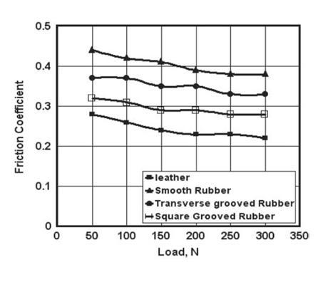 <ref>http://engineershandbook.com/Tables/frictioncoefficients.htm</ref>
Team Member Roles
- Haruhiko Okamoto (Harry) - Customer Needs, Stakeholders, System Function, Usability, Mechanical Analysis
- Yung-King Leo Ma (Leo) - Executive Summary, List of Parts, Assembly Diagrams, Failure Modes and Effects Analysis (FMEA)
- Ming- I Chou (Alex) - Design for the Environment (DFE)
- Po-Yu Chou (Bert) - Design for Manufacturing and Assembly, Mechanical Analysis
References
- F. H. Ezzat, W. Y. Ali, El-Minia and G. T. Abdel-Jaber, Aswan. "Dry Sliding of Rubber on Ceramic Surface". El-Minia University. Nov, 2008.
- SAE FMEA Standards Document: SAE J1739
- Economic Input-Output Life Cycle Assessment (EIO-LCA) US 1997 (491) model [Internet], Available from: <http://www.eiolca.net/>
<references/>
