Automatic can opener
From DDL Wiki
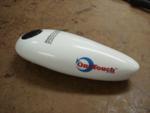
The automatic can opener provides an easier way to open cans for all people. The opener takes the work out of turning a knob as well as takes the hassle of fishing out the top from in the can. In general, it is a relatively simple design that doesn't appear to have many easy misuses. However, the few misuses we saw most often were tyring to pull the opener off too early, trying to spin it along faster than it is moving, and opening cans with tight, notched dents while large flat dents do not cause much trouble except for extra effort at the crease. The internal funtioning provides a very easy user function process, by automating everything but placing, starting, and removing the opener. It uses its own battery power to move around the can and make the job easier for the user.
Consumer needs for the product are very straight forward. A user is looking for a safe and easy alternative to traditional can openers. The use of the retractable blade is the best feature that the product has to offer for safety. The use of lightweight components also increases usability, allowing for a wider age range of users because ability to lift should not be a problem until the very extremes of young and old. The limited cycle can become tiresome when opening large cans as multiple cycles must be used. The opener can make it around a standard size can for the most part, but once on to larger cans the opener will occasionally leave a small connection of the lid between cut sections although this can be avoided with a small adjustment of the opener's position before starting the next cycle.
The opener does not overuse components entirely although some can be removed for a faster assembly time. This may also make dissassembly a little more difficult. Using quick snap connections for the injection molded parts would make assembly considerably easier, although the current molds would have to be altered in order to do so. Failure is still possible with this design as well. One flaw that would be good to fix is a small seal to make the opener water resistant. Through a series of rubber gaskets and hoods, this would be possible for rinsing purposes. This would allow for mistakes such as dropping the opener into a sink while it is out of storage. For the most part, the design is very robust and can handle most challenges.
For Market Research and Concepts for Improvement click here, automatic can opener redesign
Contents |
Product Analysis
Product Requirements and Consumer Needs:
Product requirements are a direct derivative of consumer needs and as such the two go hand in hand. The One Touch can opener must go above and beyond the capabilities of ordinary can openers. It must completely remove the tops of cans of various sizes and it must do so in a fashion that does not leave serated edges on the lid of the can. Regular can openers cut the top off of a can such a way that it can not be placed atop the can once the contents of the can are done being used. The One Touch can opener must eliminate this problem so that the contents of the can may indeed remain in the can and stay fresh and sealed while still in it. The can opener must also be light and easily maneuverable as there will be a wide age variation in consumers. It needs to run automatically without the user maintaining pressure on the switch, thus the name "One Touch." The One Touch Can Opener must run without electricity and therefore runs on batteries. As all consumers are not savy with electronic or battery operated devices, the can opener must have an easily accessible battery port that is straight forward and simple to place and replace batteries. Finally the can opener must be safe for all operators. It cuts metal so clearly it has a sharp surface which allows it to do so. The blade must be retractable so that it is concealed while the can opener is not in use and therefore the consumer can't mistakenly slice themself on a sharp edge.
Use:
The automatic can opener must first be put into the right position for it to complete its task properly. This correct position is on top of the can. Once it is in the right position the user just has to hold down the button until the opener turns on. Once it is on the user can just sit back and observe. The can opener will eventually make its way all the way around the can, unless the can is larger than standard tin cans. If this is the case, the can opener simply has to be run multiple times until the top is completely cut. Once the can opener has completed its job, the user can simply pick up the can opener. Since there is a magnet on the can opener the lid is attached and can be easily discarded.
Functional Operation:
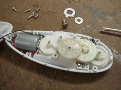
The actually internal mechanics to how the can opener works is really quite simple. To begin, setting the opener on the top of actually also presses a safety switch. From that point, the main button can be pressed to close a switch that gives power to the motor. Through a geartrain, the speed and torque output of the motor are converted to a reasonable speed with a high enough torque to move the opener around the can while cutting. As the gears move, the cutting wheel is finally exposed from is protective casing and pressed into the can. This is achieved by the cutting wheel being on a crank so that it can be rotated out from its coveruntil it pierces the can. The shaft that the crank is mounted to has a flat spot at the top of it that operates the second internal switch. While the flat spot is in position, the opener is off. Using the manual switch, the shaft turns until the rounded portion closes the internal switch. This remains pressed until the flat spot gets back into position and the opener stops. Towards the end of the cycle, the cutting wheel is once again retracted into its casing to dissengage the can. To finish the process the opener can be lifted off and actually lifts the top of the can also using a magnet. The magnet does not actually hold the can until it is being lifted as the opener cuts through the side of the can just under the rim. The magnet, although very small, has enough strength to hold at least a 6 in diameter top. There are times when multiple cycles must be used because of can size, but this does not pose much of a problem as it just requires the button to be pressed again.
Components
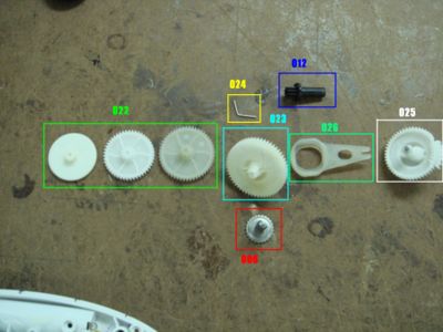
The can opener has several components and electrical assemblies. It appears that most are purchased from suppliers while casings are injection molded in house. Some components seem like they could be removed to allow for a faster and easier assembly. Also, with a large enough scale of production, it may be beneficial to begin making some of the injection molded gears in house as well. Much more detail as to what individual components are used, what their purpose is, and their likely manufacturing processes.
The geartrain is very compact although it does allow for a large conversion from motor speed to torque allowing for an easily made cut.
DFMA Analysis
Design for Manufacturing:
- The upper and lower casing are both made in house by using the method of injection molding.
- Most of the other parts like the screws, pressure switch and the motor are bought by suppliers, so it won’t be hard to buy.
- The Gear components in the gear train in this product should be currently bought from other suppliers as well and could be made in house using the process of injection mold plastics, so it shouldn't be hard to produce.
- Movement wheel and the washers are both stamped
- Overall, the whole manufacturing process is very cost effective and most of them are produced by molding and stamping.
Design for Assembly:
- The casings are securely attached by screws. It is very easy, simple and straight forward.
- The internal wiring has obvious tracks to help guide wires so it will be aligned.
- The Circuit board and the capacitors are soldered in so it will be secured and hard to disassembly.
- Gear Trains and the movement gear are all secured by shafts
- The Bent Pin is used to attach the movement gear to the movement wheel
Design for Disassembly:
- Easy dissemble for most parts as most of them are attached by shafts and screws
- The more difficult areas would be the motor itself and the circuit board (soldered in)
In general, the DFMA is well developed but has room for improvement. As many parts are outsourced, such as the gears, the manufacturing does not require much design for them. At the same time, pieces such as the casings appear to be injection molded in house. The injection molding has all necessary fillets and chamfers to make extraction of parts easier. These components could be redesigned to improve design for assembly though. By incorporation of quick snap clips into the design of the casing components, it would be possible to decrease assembly time by not having to screw in seven fasteners to attach the upper and bottom casings. The use of encasing components makes actual placement of parts easy since it all goes from one base mainly. This also makes it so individual gears do no need to be pinned into place for the most part as well as the motor is held in place only by the casing pieces. Another opportunity could be a snap together joint for the movement gear and wheel rather than the method of pinning used currently.
Design for Environment
- The can opener uses many plastics in its structure and gear train, but we do not have access to these materials causing a further analysis to be beyond our current ability.
- The components made of plastic could be made from less material, such as making thinner gears to use less of the plastic.
- Aside from design, manufacturing processes can be looked into to try and use less energy, such as using a plastic that requires less energy to heat for injection molding.
Due to the nature of designing for the environment, it is a difficult topic for our team to cover. Without specific data on materials used, we will be unable to recommend less harmful materials to take their place. At the same time, the use of less material is definitely a place for improvement as well as trying to use less energy in the manufacturing by doing things like regulating heat more in the process of injection molding or requiring less power for an assembly plant in general.
Opportunities for Improvement
- Many parts, like the gears, were ordered from suppliers but could be made in house, even though that would mean a larger cost at the beginning, it would be worth it in the long run.
- Currently the overall gear ratio is 206:1 changing an initial speed of close to 2700 rpm down to 13 rpm at the movement wheel.
- The motor offers speed but not much torque itself, which is one of the reasons why we require many gears in the gear train, so one thought is to provide a higher voltage so that there would be a higher torque.
- There are way too many screws attaching the lower case and upper case, many could be eliminated if the the design of the casing changes to include quick snap connectors.
- The switches and the reset button are exposed to the air, so if by accident the can opener is dropped into water, it could short circuit it. Because of this rubber gaskets and hoods could be used to make the device water-resistant.
- The use of less material and energy in the manufacturing process would improve how environmentally friendly the device is.
The decision to change the overall gear ratio can only be made with proper specifications for the motor telling the torque output. Without this information it is not possible to see if less torque and more speed would be a viable possibility. Its current speed is so slow that many people try to lift the opener off before it is finished which leads us to believe that only fewer gears would be a possible change as to speed up the cycle time. A different motor may provide more torque outright, but with size constraints it appears that trying to overpower the voltage a small amount for a little extra power is the only feasible option.
Failure Modes and Effective Analysis
Although there are many causes of failure, there are three failures that stand out for being the worst. Electrically short circuiting would make the device inoperable, which we see as a possibility because of accidentally dropping the unit into water. Another failure would be in the geartrain which would cause a loss of power transfer and the motor relies on a mechanical switch to decide when it turns off. This means that the motor would keep running but the opener would no longer cut further. A safety problem that we also see high is switch malfunctioning because it would cause unintended use.
| Part Number | Part Name | Failure Mode | Effects of Failure | S | Causes of Failure | O | Design Controls | D | RPN |
|---|---|---|---|---|---|---|---|---|---|
| 001 | Screws(large) | * A screw that is detached from the casings | That would lead the casings to fall apart and not attached | 2 | Due to rotting or overstress | 2 | Manual | 2 | 36 |
| 002 | Pressure switch | * It cannot not detect whether the battery case or the opener is in place | That would be dangerous and one of the safety features will be lost | 4 | Overuse and the connection between those components are loose due to deformation | 4 | Manual | 2 | 14 |
| 003 | Movement Wheel | * Cannot provide the necessary pressure to the cutting wheel to pierce can | That would make the automatic can unworkable | 2 | That may due to overuse and deformation if the opener was hit or environmental influences | 2 | Material | 3 | 4 |
| 004 | Cap Screw | * Cannot attach the cutting wheel to gearing | That would lead make the cutting wheel not work as the gears would not be able to provide the torque required | 2 | Due to rotting or overstress | 2 | Manual | 2 | 36 |
| 005 | Cutting Wheel | * Cannot cut through can to remove lid | That would make the whole can opener lose its function | 4 | Due to overuse, material corrosion | 3 | Material and Manual evaluation | 2 | 12 |
| 006 | Magnet | * Cannot keep the top off from submersing into the can when it is cut off | That would lead the can top to fall into the can | 1 | Losing its polarity due to environment | 7 | Manual evaluation | 6 | 11 |
| 007 | Reverse Switch | * It does not reverses the direction of the motor | That would lead the cutting procedure to fail | 2 | Error from the circuit board | 2 | Manual calculation and evaluation | 3 | 6 |
| 008 | Manual Pinion | * It does not allows manual rotation of the gear system | Lost the manual dimension control | 2 | Overuse and led to a lack of sensitivity | 6 | Manual calculation and evaulation | 7 | 10 |
| 009 | Positive Terminal and Negative Terminal | * No power is transmitted | The automatic opener will not have any power | 2 | The connection might be off due to deformation | 3 | Manual evaluation | 4 | 15 |
| 010 | Main button | * No power is transmitted | The automatic opener will not start | 2 | The connection might be off due to deformation | 3 | Manual evaluation | 4 | 15 |
| 011 | Internal Switch | * No circuit so there will be no power | The circuit will not be complete | 8 | The connection might be off due to deformation | 4 | Manual evaluation | 5 | 17 |
| 012 | Motor | * Cannot drives geartrain, movement wheel, and cutting wheel | The motor is the element to provide speed and connection to the gears | 4 | Overuse, overheat | 2 | Material, Manual evaluation | 6 | 12 |
| 013 | Ratio Gears | * Unable to gear down motor output | The whole can will be inoperative | 2 | Overuse, deformation | 3 | Material, Manual evaluation | 4 | 24 |
| 014 | Shafts | * Unable to sustain the gear train to usable speed and torque | The whole can will be inoperative | 6 | Overuse, deformation | 3 | Material, Manual evaluation | 7 | 36 |


