From DDL Wiki
Executive Summary
Stakeholders and Needs
Product Usage
Insert 3 D cell batteries, or plug a DC power convertor into the feeder. Align the hopper with the base to allow insertion, then twist to lock in position. Inser the bowl into the feeder base, connecting the hooks inside the base. Fill the hopper from the top with pet food and align the lid to the hopper using the arrows. Insert the lid and twist. Food must be dog or cat food, and cannot be a treat, canned food, or moist.
Turn the feeder on using the switch on the bottom. The feeder can be scheduled to provide three meals of varying sizes per day. Each meal is adjusted with 0.25 cup increments. To set meals and schedule, hold the ENTER button for 2 seconds. Using the up and down arrows, select the meal you would like to edit with the ENTER button. This will allow you to edit the time of the meal, followed by the meal size, if changes are desired. Once all meals are edited, press ENTER and the feeder will reenter the automated feeding mode. To manually feed the pet, hold the up arrow button and the feeder will provide a meal the size of the scheduled breakfast meal.
Mechanical Function
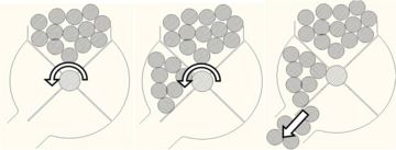
The fins in the feeder base rotate, able to move 1 cup of food in a full rotation.
The image above is a profile of the fin section of the feeder. The hopper containing the food is located directly above the fin section, thus providing the food from that location. The bowl is located at the bottom left of the diagram. The opening at the bottom left allows food to drop into the bowl.
The feeder base contains four sets of fins, each connected to an axis parallel to the floor. Gravity pulls pet food from the hopper into the fin section at the highest point of rotation. At the time of a meal, the motor rotates a worm gear, which rotates a gear in a timing belt system. One end of the belt receives rotation from the motor, and causes rotation of the fins. This provides food to the bowl since each quarter rotation transports 1/4 cup of food. Limit switches allow the motor to provide only the scheduled amount of food preset by the user. For example, if programmed to give 1/2 cup for lunch, the motor will stop rotating after the amount of two fin sections are dropped into the bowl. Keep in mind that the volume between two adjacent fins is 1/4 of a cup. The food is transported to an area where it can drop into the bowl hooked to the bottom of the base.
Mechanical Analysis
Bill of Materials
| Part # | Name | Qty. | Material | Manufacturing | Weight | Function | Photo
|
| 01
| lid | 1 | plastic | molding | 203g | provide a cover for food storage to ensure freshness and prevent pet from eating from the top | 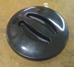
|
| 02
| hopper | 1 | plastic | molding | 223g | reservoir of food used to feed | 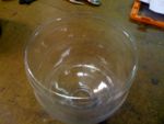
|
| 03
| dish | 1 | plastic | molding | 219g | holds portioned food for pet to eat | 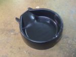
|
| 04
| battery cover | 1 | plastic | molding | 17g | protects and supports batteries | 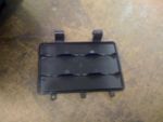
|
| 05
| black screw | 4 | metal | purchased | <1g | hold parts together | 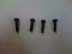
|
| 06
| gold screw | 4 | metal | purchased | <1g | hold parts together | 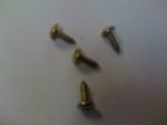
|
| 07
| silver screw | 2 | metal | purchased | <1g | hold parts together | 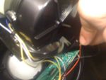
|
| 08
| display cover | 1 | clear plastic | molding | 13g | second layer to protect digital display and to smooth the look of the outside of feeder | 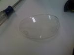
|
| 09
| tiny gold screw | 2 | metal | purchased | <1g | hold parts together | 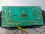
|
| 10
| tiny silver screw | 6 | metal | purchased | <1g | hold parts together | 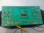
|
| 11
| display buttons | 1 | plastic | molding | <1g | allow user to interface with electrical equipment from the outside of the feeder | 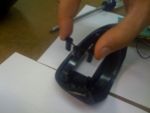
|
| 12
| screen plate | 1 | plastic | molding | 8g | first layer to protect digital display screen | 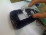
|
| 13
| display faceplate | 1 | plastic | molding | 31g | protects the electrical gear and digital plate and provides a finished look to the product | 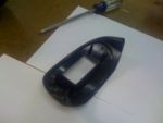
|
| 14
| gold screw | 3 | metal | purchased | <1g | hold together the main gear apparatus | 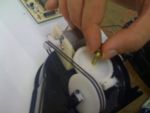
|
| 15
| 'eyeglass' black screw | 2 | metal | purchased | <1g | hold parts together | 
|
| 16
| fastening bracket for #15 | 2 | nylon | casting | <1g | provides a base for the #15 screws to attach to |
|
| 17
| pulley bands | 2 | plastic | casting | <1g | transfers energy from motor to gear base to turn spinner blades |
|
| 18
| worm gear assembly | 1 | asst. | | 7g | transfers energy and motion |
|
| 19
| silver screw (round head) | 2 | metal | purchased | <1g | hold parts together |
|
| 20
| silver screw (flat head) | 4 | | metal | purchased | hold parts together |
|
| 21
| spinner cover half (no mount) | 1 | ABS | molding | 53g | acts as a guide for the food into the dish and protects and houses the spinner apparatus |
|
| 22
| spinner blades | 4 | plastic | molding and cutting | <1g | portion out food and then turn to allow food to drop into dish |
|
| 23
| spinner axle | 4 | plastic | molding | 6g | base for spinner blades and thing that is torqued to move blades |
|
| 24
| bushing/bearing | 1 | plastic | purchased | <1g | provide spacing and reduce friction |
|
| 25
| spinner gear | 1 | nylon | casting | 5g | turn spinner axle |
|
| 26
| long silver screw | 2 | metal | purchased | <1g | hold parts together |
|
| 27
| motor mount | 1 | plastic | molded | 7g | to provide a stable place for the motor to attach |
|
| 28
| spinner cover half (with mount) | 1 | plastic | molding | 57g | acts as a guide for the food into the dish and protects and gives a mount for the spinner apparatus |
|
| 29
| base | 1 | plastic | molding | 146g | mount for all of the machine. is the weight that keeps it upright and connects the pieces together |
|
| 30
| circuit board | 1 | asst. | asst. purchased | 99g | all electrical equipment for using outlet power and telling motor when to move |
|
| 31
| limit switch | 1 | asst. | asst. purchased | <1g | limits motor movement |
|
| 32
| motor | 1 | asst. metal | asst. purchased | 37g | provides transfer of electrical to mechanical energy for system |
|
| 33
| on/off switch | 1 | plastic | molding | <1g | user interface to shut machine off |
|
Design for Manufacturing and Assembly
The dog feeder is already manufactured very simply and efficiently. The part count is low and only necessary parts were manufactured. The design is very simple. Most parts are plastic and thus easily manufactured with casting or molding, which is the method chosen. The material should not be changed because plastic is the most logical choice for reasons of cost and ease of manufacturing. Any change in material would spike the price of the machine.
Failure Modes and Effects Analysis
Design for Environment
Team Member Roles
Lauren Walch - DFMA and Bill of Materials (BOM)
References


