Bike lock
From DDL Wiki
(Difference between revisions)
(→Puck Lock) |
(→Puck Lock) |
||
| Line 609: | Line 609: | ||
| align="center"|'''Minimize Part Count''' | | align="center"|'''Minimize Part Count''' | ||
| Row 1, column 2 | | Row 1, column 2 | ||
| - | | | + | | |
| + | * The chain assembly itself contains a lot of parts (chain link, chain pin, chain spacer) | ||
|- | |- | ||
| align="center"|'''Minimize Assembly Surfaces''' | | align="center"|'''Minimize Assembly Surfaces''' | ||
| Line 616: | Line 617: | ||
|- | |- | ||
| align="center"|'''Use Subassemblies''' | | align="center"|'''Use Subassemblies''' | ||
| - | | | + | | |
| + | * The chain can be assembled separate from the main housing assembly | ||
| Row 2, column 3 | | Row 2, column 3 | ||
|- | |- | ||
| align="center"|'''Mistake-Proof''' | | align="center"|'''Mistake-Proof''' | ||
| - | | | + | | |
| + | * Parts of the main housing assembly have features that allow only one way of assembly | ||
| Row 2, column 3 | | Row 2, column 3 | ||
|- | |- | ||
| align="center"|'''Minimize Fasteners''' | | align="center"|'''Minimize Fasteners''' | ||
| - | | | + | | |
| - | | | + | | |
| + | * There are fasteners between each chain link | ||
|- | |- | ||
| align="center"|'''Minimize Handling''' | | align="center"|'''Minimize Handling''' | ||
Revision as of 09:24, 2 February 2014
Contents |
Executive Summary
Product Stakeholder Analysis
Product Usage Study
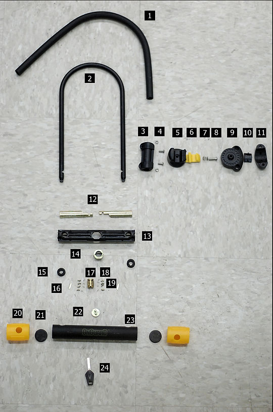
Bill of Materials
U-Lock
| Part # | Name | Quantity | Subassembly | Mass [g] | Function | Material | Manufacturing Process | Image |
|---|---|---|---|---|---|---|---|---|
| 1 | Rubber Shielding | 1 | N/A | 68 | Provides weatherproofing for the U-Bar. It keeps dirt and grime out and prevents scratches. In comparison to the U-Bar it is plush and nice to the touch. | Rubber | Extrusion | |
| 2 | U-Bar | 1 | N/A | 330 | Can be placed around the chosen locking surface and the bike frame. This is then inserted into the base of the U-Lock and secures the bike to the locking surface. | Steel | Extruded, Bent, Cut | |
| 3 | U-Bar Clamp Attachment | 1 | Bike Frame Clamp | 15 | Provides nice mating surface for U-Bar and bike frame bracket. | Plastic | Injection Molding | |
| 4 | Frame Attachment Screws and Nuts | 4 | Bike Frame Clamp | 1 | Screws and nuts used to press clamp edges together around the U-Bar. | Steel | Off the Shelf | |
| 5 | U-Bar Frame Attachment Clasp | 1 | Bike Frame Clamp | 13 | Nicely holds onto the U-Bar and connects to a base piece that can be attached to a bike frame. | Plastic | Injection Molding | |
| 6 | U-Bar Frame Attachment Locking Tab | 1 | Bike Frame Clamp | 4 | Tab presses over edge of Clamp attachment on the U-Bar to secure it to the bike frame. | Plastic | Injection Molding | |
| 7 | U-Bar Frame Attachment Spring | 1 | Bike Frame Clamp | <1 | Spring sits under clasp and provides force on clasp to keep Lock attached to frame attachment. | Steel | Off the SHelf | |
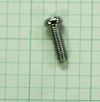
| 8 | Frame Attachment Joining Screw | 1 | Bike Frame Clamp | <1 | Fastens the two major parts of the frame bracket together | Steel | Off the Shelf | |
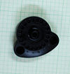
| 9 | Frame Bracket Base | 1 | Bike Frame Clamp | 17 | Holds clasp. Has specific points of rotation so one can change the orientation of the clasp as it connects to the bike. Represents half of the frame bracket clamp. | Plastic | Injection Molding | |
| 10 | Mating Pad | 2 | Bike Frame Clamp | 2 | Snap in part is smooth and offers a nice mating surface between the clamp and the bike frame (Not Pictured), and the U-Lock and clamp. | Plastic | Injection Molding | |
| 11 | Bike Frame Bracket Clamp | 1 | Bike Frame Clamp | 18 | Part is placed around bike frame and fastened to the rest of the bracket via screws. Second half of frame bracket clamp. | Plastic | Injection Molding | |
| 12 | Locking Bars | 2 | Locking Mechanism | 26 | Bars fit into notches cut into the U-Bar. When they are in place they secure the U-Bar in place and prevent its removal. The hooks on either edge sit on nubs that rotate when the key is turned, sliding the locking bars back and forth. | Brass | Forged | |
| 13 | Lock Component Housing Cylinder | 1 | Lock Mechanism | 28 | Neatly holds all the parts necessary to actually lock the lock. It has slots cut such that one cannot insert the lock upside down, tracks for the lock bars to slide on, and is designed such that all force imparted to the lock in an attempt to shock it open are directed around the lock bars. | Plastic | Injection Molding | |
| 14 | Lock Housing | 1 | Lock Mechanism | 15 | Housing is made to nicely keep the lock in place inside of the component housing cylinder. It has a tab to prevent incorrect insertion of lock. | Brass | Off the Shelf | |
| 15 | Rubber Grommet | 2 | N/A | <1 | Acts as both a seal to prevent dirt or water from entering the lock component housing cylinder, as well as a cushion to protect the cylinder from rubbing directly against the U-Bar | Rubber | Stamping | |
| 16 | Lock Stopper Pin | 2 | Lock Mechanism | <1 | Grooves in the lock housing fit around these spring loaded pins. When the key is concerned, These pins are compressed and allow the lock to turn. | Brass | Stamping | |
| 17 | Pin Housing | 1 | Lock Mechanism | 8 | Housing has space for spring and pins as well as the stopper pins and springs. Has a slot for a key to be inserted. Pin Housing will rotate around inside the lock housing. | Brass | Off the Shelf | |
| 18 | Pin Springs | 12 | Row 1, column 4 | Row 1, column 5 | Pins sit on top of these springs. When the key is inserted and turned, these springs will compress or extend to get all the pins to the same height so the pin housing can rotate. They will return to their natural length after the key is removed. | Row 1, column 7 | Row 1, column 8 | Row 1, column 9 |
| 19 | Pins | 8 | Row 1, column 4 | Row 1, column 5 | These pins are each individually made with notches at a different height. The height of the notch corresponds to the pattern on the key. The correct key will line up with the notches, allowing the pins to be moved out of the way, allowing the pin housing. | Row 1, column 7 | Row 1, column 8 | Row 1, column 9 |
| 20 | Plastic Endcap | 2 | N\A | 13 | Acts as a weatherproofing seal for the outer casing of the lock base. It also seals off the ends of the lock base via a tight fit, discouraging the user from tampering with the internals of the lock. Adds a stylistic element to the lock. | Soft Plastic | Molding | |
| 21 | Rubber Shock Absorber | 2 | N\A | 4 | Part acts as a weatherproofing seal as well as a shock absorber. Cushions any force that is applied to the ends of the lock. This prevents the lock from being bumped open. | Rubber | Stamping | |
| 22 | Lock Bar Actuator | 1 | Row 1, column 4 | Row 1, column 5 | Slides into grove on back of pin housing. When pin housing rotates, this part rotates as well. The Lock Bars are attached to the nubs on top and turning the pin housing causes the lock bars to slide from unlocked to locked. | Brass | Row 1, column 8 | Row 1, column 9 |
| 23 | Outer Housing | 1 | Lock Housing | 127 | A powder coated outer case that neatly houses the entire lock assembly. Has holes in it to accomodate the U-Bar ans well as a small hole in it, presumably for assembly alignment purposes. Coating adds plesant feel in comparison to unfinished steel. | Steel | Stamping and Welding | |
| 24 | Key | 5 | N\A | 6 | Key is specially made to line up with each of the pins in a specific lock. The track pulls the pins into the correct position, which allows the lock to rotate. | Steel and Plastic | Row 1, column 8 |
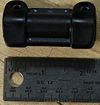
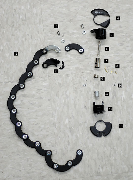
Puck Lock
| Part # | Name | Quantity | Subassembly | Mass | Function | Material | Manufacturing Process | Image |
|---|---|---|---|---|---|---|---|---|
| 1 | Row 1, column 2 | Row 1, column 3 | Row 1, column 4 | Row 1, column 5 | Row 1, column 5 | Row 1, column 7 | Row 1, column 8 | Row 1, column 9 |
| 2 | Row 1, column 2 | Row 1, column 3 | Row 1, column 4 | Row 1, column 5 | Row 1, column 5 | Row 1, column 7 | Row 1, column 8 | Row 1, column 9 |
| 3 | Row 1, column 2 | Row 1, column 3 | Row 1, column 4 | Row 1, column 5 | Row 1, column 5 | Row 1, column 7 | Row 1, column 8 | Row 1, column 9 |
| 4 | Row 1, column 2 | Row 1, column 3 | Row 1, column 4 | Row 1, column 5 | Row 1, column 5 | Row 1, column 7 | Row 1, column 8 | Row 1, column 9 |
| 5 | Row 1, column 2 | Row 1, column 3 | Row 1, column 4 | Row 1, column 5 | Row 1, column 5 | Row 1, column 7 | Row 1, column 8 | Row 1, column 9 |
| 6 | Row 1, column 2 | Row 1, column 3 | Row 1, column 4 | Row 1, column 5 | Row 1, column 5 | Row 1, column 7 | Row 1, column 8 | Row 1, column 9 |
| 7 | Row 1, column 2 | Row 1, column 3 | Row 1, column 4 | Row 1, column 5 | Row 1, column 5 | Row 1, column 7 | Row 1, column 8 | Row 1, column 9 |
| 8 | Row 1, column 2 | Row 1, column 3 | Row 1, column 4 | Row 1, column 5 | Row 1, column 5 | Row 1, column 7 | Row 1, column 8 | Row 1, column 9 |
| 9 | Row 1, column 2 | Row 1, column 3 | Row 1, column 4 | Row 1, column 5 | Row 1, column 5 | Row 1, column 7 | Row 1, column 8 | Row 1, column 9 |
| 10 | Row 1, column 2 | Row 1, column 3 | Row 1, column 4 | Row 1, column 5 | Row 1, column 5 | Row 1, column 7 | Row 1, column 8 | Row 1, column 9 |
| 11 | Row 1, column 2 | Row 1, column 3 | Row 1, column 4 | Row 1, column 5 | Row 1, column 5 | Row 1, column 7 | Row 1, column 8 | Row 1, column 9 |
| 12 | Row 1, column 2 | Row 1, column 3 | Row 1, column 4 | Row 1, column 5 | Row 1, column 5 | Row 1, column 7 | Row 1, column 8 | Row 1, column 9 |
| 13 | Row 1, column 2 | Row 1, column 3 | Row 1, column 4 | Row 1, column 5 | Row 1, column 5 | Row 1, column 7 | Row 1, column 8 | Row 1, column 9 |
DFMA
U-Lock
| Design for Manufacture Guidelines | ||
|---|---|---|
| Design Objective | Strengths | Weaknesses |
| Minimize Part Count |
|
|
| Standardize Components |
|
|
| Commonize Product Line |
| |
| Standardize Design Features |
|
|
| Keep Designs Simple |
|
|
| Multifunctional Parts |
| |
| Ease of Fabrication |
| |
| Avoid Tight Tolerances |
|
|
| Minimize Secondary and Finishing Operations |
| |
| Take Advantage of Special Process Properties |
| |
| Design for Assembly Guidelines | ||
|---|---|---|
| Design Objective | Strengths | Weaknesses |
| Minimize Part Count |
| Row 1, column 3 |
| Minimize Assembly Surfaces | Row 2, column 2 | Row 2, column 3 |
| Use Subassemblies |
| Row 2, column 3 |
| Mistake-Proof |
| Row 2, column 3 |
| Minimize Fasteners |
| Row 2, column 3 |
| Minimize Handling | Row 2, column 2 | Row 2, column 3 |
| Minimize Assembly Direction | Row 2, column 2 | Row 2, column 3 |
| Provide Unobstructed Access | Row 2, column 2 | Row 2, column 3 |
| Maximize Assembly Compliance | Row 2, column 2 | Row 2, column 3 |
Puck Lock
| Design for Manufacture Guidelines | ||
|---|---|---|
| Design Objective | Strengths | Weaknesses |
| Minimize Part Count |
|
|
| Standardize Components |
| Row 2, column 3 |
| Commonize Product Line |
| Row 2, column 3 |
| Standardize Design Features |
| Row 2, column 3 |
| Keep Designs Simple | Row 2, column 2 | Row 2, column 3 |
| Multifunctional Parts |
| Row 2, column 3 |
| Ease of Fabrication | Row 2, column 2 | Row 2, column 3 |
| Avoid Tight Tolerances |
| Row 2, column 3 |
| Minimize Secondary and Finishing Operations | Row 2, column 2 | Row 2, column 3 |
| Take Advantage of Special Process Properties |
| Row 2, column 3 |
| Design for Assembly Guidelines | ||
|---|---|---|
| Design Objective | Strengths | Weaknesses |
| Minimize Part Count | Row 1, column 2 |
|
| Minimize Assembly Surfaces | Row 2, column 2 | Row 2, column 3 |
| Use Subassemblies |
| Row 2, column 3 |
| Mistake-Proof |
| Row 2, column 3 |
| Minimize Fasteners |
| |
| Minimize Handling | Row 2, column 2 | Row 2, column 3 |
| Minimize Assembly Direction | Row 2, column 2 | Row 2, column 3 |
| Provide Unobstructed Access | Row 2, column 2 | Row 2, column 3 |
| Maximize Assembly Compliance | Row 2, column 2 | Row 2, column 3 |
