From DDL Wiki
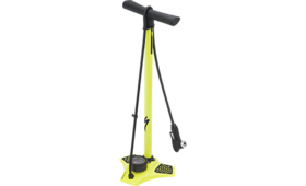
Figure 1: Competitor product used for dissection study
Executive Summary
This will be a brief executive summary that describes the key findings and recommendations.
Lorem ipsum dolor sit amet, consectetur adipiscing elit. Ut elementum elit vel tortor scelerisque auctor. Donec urna dui, eleifend eget adipiscing vulputate, feugiat id nisl. Donec mattis, quam in tincidunt ullamcorper, orci tellus condimentum dui, aliquet faucibus risus nunc et nunc. Vestibulum metus justo, volutpat sed consequat eget, mollis sed neque. Maecenas dignissim hendrerit malesuada. Aliquam dictum gravida orci ut rutrum. Fusce eros lectus, accumsan sed rhoncus eu, tempor sed magna. In ac lacus urna, ut cursus nisl. Curabitur ac dui nisl, in imperdiet orci. Aliquam quam dui, tincidunt quis volutpat quis, convallis a ipsum. Suspendisse quis molestie lorem. Nunc vel magna commodo nunc viverra tempor id blandit neque. Donec nec elementum ligula. Cras accumsan, urna eget dictum varius, arcu nunc porttitor tortor, sit amet feugiat nisl elit vitae elit. Proin eget tellus lectus, tempus tincidunt augue. Sed sagittis iaculis orci, sit amet tempus dui tincidunt in.
Product Stakeholders
We have identified possible needs and wants for all possible stakeholders. The identified needs are those needs that are essential in order to encourage the stakeholder to use it. The identified wants are additional features that may benefit the stakeholder, however, they are not vital to the use of the product. For the purpose of this study, the consumer is the person pumping up the bike tire, not necessarily the bike owner.
| Stakeholder Needs and Wants
|
| Stakeholder | Needs | Wants
|
| Consumer
|
- Product should not require much force or time during pumping process
- Mechanical advantage and efficiency during the pumping process
- Intuitive
|
- Balances strong performance and minimal cost
- Lightweight and space efficient
- Ergonomic
- Durability
|
| Retailer
|
- Cheap & durable materials
- Efficient storage
|
- Aesthetically appealing
- Standardization
|
| Manufacturer
|
- Cheap & easily processed materials
- Mass production
- Easy assembly
|
- Volume-efficient materials
|
| Shipping & Transportation
|
|
- Space-efficient packaging
|
Product Use Study
This is where we will document in detail how the product is used, step by step, and summarize findings from our user studies with photo documentation.
Product Mechanical Function
We will include some pretty diagrams and information about the mechanical function of our part.
Assembly
This is where we will have information/photo about the major assembly.
An exploded view of the floor bike pump will be inseted here... with all components labeled.
Sub-Assembly
We may need to include detailed sub-assembly photos and information here.
This is where we will insert exploded views of each internal sub-assembly with labeled components and a brief summary of each sub-assembly function.
Bill of Materials
The following is a bill of materials from the bike pump dissection. The parts can be sorted based on part number, quantity, weight or material by clicking on the appropriate tab at the top of the table.
| Part Number
| Name
| QTY
| Weight (g)
| Function
| Material
| Manufacturing Process
| Image
|
| 1 | Screw | 5 | 4 | Holds base support (#8) in place to metal base (#31) | Steel | *** |
|
| 2 | Nut | 5 | 1 | Attaches screws (#1) to metal base (#31) | Steel | *** |
|
| 3 | Rubber readout cover | 1 | 30 | Holds plastic readout cover (#4) in place above pressure gauge mechanics (#23) | Rubber | *** |
|
| 4 | Plastic readout cover | 1 | 12 | Provides clear screen and protection to number dial readout (#10) | Plastic | Injection Molding |
|
| 5 | Metal connection valve tip | 1 | 5 | Holds rubber connection valve tip (#6) in place | Aluminum | Press Molding + Threading | 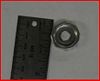 Metal connection valve tip |
| 6 | Rubber connection valve tip | 1 | 2 | Creates seal onto bike tube valve | Rubber | *** | 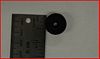 Rubber connection valve tip |
| 7 | Air hose holder (double) | 1 | 12 | Holds air hose (#32) to main tube (#30) during storage | Plastic | Injection Molding |
|
| 8 | Plastic base support | 1 | 10 | Reduces cantilever stresses on outer arm tube | Plastic | Injection Molding |
|
| 9 | #7 O-Ring | 2 | < 1 | Provides necessary friction to hold the double air hose holder (#7) onto outer arm tube (#30) and allow for vertical movement along axis of tube | Rubber | *** |
|
| 10 | Readout number dial | 1 | 3 | Provides a quantified tire pressure readout | Aluminum | Sheet Stamped |
|
| 11 | Readout needle | 1 | < 1 | Displays the quantified tire pressure on (#10) | Aluminum | Press Stamped |
|
| 12 | #13 O-Ring | 2 | < 1 | Provides seal on bike tube inside the pump stabalizer (#13) | Rubber | *** |
|
| 13 | Pump stabalizer | 1 | 13 | Allows metal rod (#19) to move within the main tube (#30) | Plastic | Injection Molding |
|
| 14 | Piston head | 1 | 8 | Acts as a pump to draw in air within the main tube (#30) and then compress the air | Plastic | Injection Molding |
|
| 15 | Tube connector | 2 | 4 | Connects hose (#32) to nozzle (#***) and to the metal base (#31) | Plastic | Injection Molding |
|
| 16 | Air hose holder (single) | 1 | 2 | Holds air hose (#32) to main tube (#30) during storage | Plastic | Injection Molding |
|
| 17 | Handle bar | 1 | 127 | Allows user to apply downward force to draw and compress air in the main tube (#30) | Plastic | Injection Molding |
|
| 18 | End cap | 2 | 6 | Provides a covering to the ends of the handle bar | Plastic | Injection Molding |
|
| 19 | Metal rod | 1 | 174 | Connects piston head (#14) to the handle bar (#17) | Steel | Extrusion + Crimp |
|
| 20 | Stopper | 1 | < 1 | Blocks airflow during upstroke | Rubber | *** |
|
| 21 | Spring | 1 | < 1 | Pushes up stopper | Steel | Coiled Wire |
|
| 22 | O-Ring | 1 | < 1 | Creates seal | Rubber | *** |
|
| 23 | Pressure gauge mechanics | 1 | 50 | Converts air pressure to angular displacement | Copper | *** |
|
| 24 | Small screw | 2 | < 1 | Fixes pressure gauge housing | Steel | *** |
|
| 25 | Air flow director | 1 | 49 | Guides air flow from piston to hose | Plastic | Injection Molding + Threading |
|
| 26 | #27 O-Ring | 1 | < 1 | Provides a seal to *** (#27) | Rubber | *** |
|
| 27 | Hose to nozzle connector | 1 | < 1 | Allows air to flow from hose to nozzle | Plastic | *** |
|
| 28 | Seal between #25 & #29 | 1 | < 1 | Provides a seal between the air flow director (#25) and *** (#29) | Rubber | *** |  *** Seal between #25 & #29 |
| 29 | Base hose connector | 1 | 7 | Provides a connection between hose (#32) and air flow director (#25) | Plastic | Injection Molding | 
|
| 30 | Main tube | 1 | 238 | House piston | Steel | Injection Molding + Threading |
|
| 31 | Metal base | 1 | 540 | Provides counter force from upstroke | Steel | Molded + Drill Pressed | 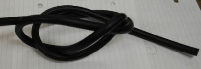
|
| 32 | Hose | 1 | 83 | Encloses from base to nozzle | Rubber | *** |
|
| 33 | Weighted handle insert | 1 | *** | *** | Aluminum | *** |
|
| 34 | Valve connection housing | 1 | *** | Gripping surface | Plastic | Injection Molding |
|
| 35 | Valve channel | 1 | *** | Channels air through handle | Plastic | Injection Molding |
|
| 36 | Tire interface valve | 1 | *** | Puts air in tire | Steel | *** |
|
| 37 | Readout housing | 1 | *** | Protection of pressure gauge | Steel | Press Molded |
|
| 38 | Piston chamber end cap | 1 | *** | Fixes main tube to base | Steel | *** | }
Design for Manufacture and Assembly (DFMA)
- INCLUDE AN INTRODUCTION AS TO WHAT DFMA IS
Manufacturing
The competitor product we analyzed displayed numerous positive manufacturing features that would minimize cost and complexity. The overall design is surprisingly simple, a result of combining features into single parts where possible, using only a few different materials, and minimizing the overall part count. (INSERT COMPONENT WITH BIGGEST ROOM FOR IMPROVEMENT AND WHY).
Below are some of the DFM Guidelines and the observations we made of how our competitor designed their product with those guidelines in mind and some areas we believe they could improve.
| Design for Manufacturing Features and Improvements
|
| Design Objective | Strengths | Areas of Improvement
|
| Minimize Part Count
|
- Few fasteners, mostly everything screws and locks together
- Many multifunctional components leading to less parts overall
|
|
| Standardize Design Features
|
- All screws in the system are identical
|
- Since there are few fasteners, most parts are custom-made for this product
|
| Keep Designs Simple
|
- Piston shows a clever design to allow air into the pump on upstroke while eliminating lost air on downstroke, while still remaining very simple
|
- Pressure gauge is very complex, needs fine adjustment and much protection
|
| Multifunctional Parts
|
- Many parts serve a specific purpose while also screwing into the next assembling acting as both a functional piece and connector
|
|
| Ease of fabrication
|
- Mostly composed of some type of plastic and steel
|
- The plastic parts are for the most part unique and would each need their own mold
|
| Avoid Tight Tolerances
|
- Uses flexible rubber o-rings to allow for larger tolerances while remaining airtight
|
|
| Minimize Secondary & Finishing Operations
|
|
- Since parts are multifunctional, most would require at least would need a secondary threading operation
|
Assembly
Assembly of the competitor's product is not the consumer's responsibility and occurs prior to the retail stages in the supply chain. The product requires tools and fasteners only where the piston chamber attaches to the base, and nearly all of the remaining interfaces are threaded. While minimizing toolage, this raises many challenges with orientation and radial symmetry where the assembly process could be made clearer. The variety of O-rings, springs, and cylinder diameters is another weakness that has room for improvement.
Due to the assembly process being deliberately separated from the consumer, ease of assembly is not a high priority and leaves room for redesign towards simplicity.
| Design for Assembly Features and Improvements
|
| Design Objective | Strengths | Areas of Improvement
|
| Minimize Part Count
|
|
- There’s the metal piece in the handle we can’t account for
- Air flow pathway has several components
|
| Minimize Assembly Surfaces
|
|
- Baseplate has multiple interfaces, axes
- Piston has multiple planes and axes
|
| Use Sub-assemblies
|
- Pressure Gauge is a discrete system
- Air compression mechanics are limited to main tube
- Nozzle is a discrete system
|
- Functional testing requires end-to-end assembly
|
| Mistake-Proof
|
|
- Many radially symmetric parts
|
| Minimize Fasteners
|
- Most of the assembly is screwed together
|
- Tools and fasteners required for fixing main tube to base
|
| Minimize Handling
|
- Hose attachments have conical guides
|
- Interfaces have many different axes and planes
|
| Minimize Assembly Direction
|
|
- Two distinct possible assembly directions (Nozzle or Handle)
|
| Provide Unobstructed Access
|
|
- Base plate obscures airflow components
- Nozzle has multiple hidden components
- Pressure gauge mechanics are hard to access
|
| Maximize Assembly Compliance
|
|
|
Failure Modes & Effects Analysis (FMEA)
- NEED TO INCLUDE INTO AS TO WHAT FMEA IS
- INCLUDE THE SCALE USED TO DETERMINE S/O/D VALUES
- THEN, ADD TO REFERENCE SECTION THE SOURCE FOR THE SCALE
| Failure Modes and Effects Analysis - Floor Bike Pump
|
| Item & Function | Failure Mode | Effects of Failure | S | Causes of Failure | O | Design Controls | D | RPN | Recommended Actions
|
| Valve Nozzle Connector | Air leaking out of wheel | Bike tube loses air | 3 | Misalignment to valve | 2 | Check if it locks | 2 | 12 | Something to help user better secure nozzle properly
|
| Does not lock | No air transfer into wheel | 3 | User not using it correctly | 2 | Check if it locks | 3 | 18 | Something that does not use a lock, Make it easier to lock
|
| Valve may not fit | No air transfer into wheel | 1 | Wrong valve type | 4 | Check if it locks | 4 | 16 | Make a universal valve, Provide adapters
|
| Pressure Gauge | Air leaking out of wheel | Won't display pressure | 2 | Broken gauge | 1 | Test in manufacturing plant | 2 | 4 | Better pressure gauge tube seal, Different pressure reading technique
|
| Incorrectly calibrated | Displays incorrect pressure reading | 2 | Dropping gauge, Manufacturing error
| 1 | Test in manufacturing plant | 7 | 14 | --
|
| Handle rod | Bends | Can not apply downward force, Breaks rod | 5 | Bars are physically bent forward and not down, Damaged, Improper use | 2 | -- | 7 | 70 | Stronger rod
|
| Tube | Air leaking out of wheel | Loss of air from tire | 3 | Misuse, Damage | 3 | -- | 4 | 36 | Tube wrapped in durable material
|
Design for Environment (DFE)
Design for Environment (DFE) can help bring focus to specific areas when improving a design. By analyzing the entire life cycle, the areas of the largest impact can be determined and minimized.
| Design for Environment
|
| -- | Production | Use
|
| Item Consumed
| Bike Pump | Bike
|
| Sector # and Name
| #339920: Sporting and athletic goods manufacturing | #336991: Motorcycle, bicycle, and parts manufacturing
|
| Reference Unit
| 1 Bike Pump | 1 Bike
|
| Units consumed per product life
| 1 | 1
|
| Cost Per Unit*
| $39.04 | $234.27
|
| Lifetime Cost*
| $39.04 | $234.27
|
| Sector mtCO2e per $1M
| 613 | 543
|
| Implied mtCO2e per product life
| 0.0239 | 0.1272
|
| CO2e Tax @ $30/mtCO2e
| $0.72 | $3.82
|
*2002 USD
Production
Using the sporting and athletic goods manufacturing sector of EIO-LCA, we were able to estimate the environmental impact of producing the bike pump. The bike pump costs $50 today, which is about $39.04 in 2002. Power generation and supply has the largest contribution to the 613 mtCO2e per 1 million dollars spent in the sporting and athletic goods manufacturing category. Therefore we can estimate that for every bike pump produced 0.0239 mtCO2e is released into the environment, resulting in a minor $0.72 tax per pump.
Sector #339920: Sporting and athletic goods manufacturing
Economic Activity: $1 Million Dollars
Displaying: Greenhouse Gases
Number of Sectors: Top 10
NEED TO CITE: http://www.eiolca.net/cgi-bin/dft/display.pl?hybrid=no&first_level_sector=Other+Miscellaneous+Manufacturing&second_level_sector=339920&newmatrix=US430CIDOC2002&key=23253747582&value=2527872121&incdemand=1&selectvect=gwp&select_button1=Run+Model
Use
If the consumer purchases a bike pump, we can assume that they own at least one bike. Therefore we used the EIO-LCA Motorcycle, bicycle, and parts manufacturing sector to study the environmental impact of use of the pump. We estimated that today the average bike costs $300 which equates to about $234.27 in 2002. Our analysis approximated a small $3.82 tax per bike.
Sector #336991: Motorcycle, bicycle, and parts manufacturing
Economic Activity: $1 Million Dollars
Displaying: Greenhouse Gases
Number of Sectors: Top 10
NEED TO CITE: http://www.eiolca.net/cgi-bin/dft/display.pl?hybrid=no&first_level_sector=Vehicles+and+Other+Transportation+Equipment&second_level_sector=336991&newmatrix=US428PURCH2002&key=5727070922&value=1515705675&incdemand=1&selectvect=gwp&select_button1=Run+Model
Group Dynamic
 Group 2: JR, Patrick, Dinesh, Lauren, Amber Team Leader: Dinesh Ayyappan
DFMA Lead: Patrick Hogan
FMEA Lead: Jonathan Wong
DFE Lead: Amber Ohiokpehai
Wiki Page Programmer/Report Compilation: Lauren Milisits
References
This is where we should list any references that we used throughout the process of our report.
|


