Blender
From DDL Wiki
(→Product Dissasembly) |
(→Product Dissasembly) |
||
| Line 134: | Line 134: | ||
|- | |- | ||
! 032 | ! 032 | ||
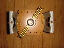
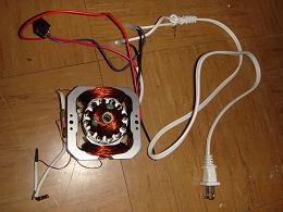
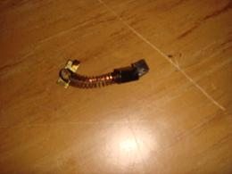
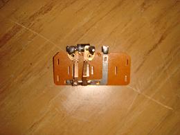
| - | | Motor Assembly || 1/331 || Assembly made of copper coil wrapped around a plastic base and a stainless steel square with large copper coils on either side. Receives a current from the electricity source which is then used to generate a magnetic field. Magnetic field rotates motor shaft. Black controller bock regulates impulse from motor. || Stainless Steel, Aluminum, Plastic, Plastic Wiring || | + | | Motor Assembly || 1/331 || Assembly made of copper coil wrapped around a plastic base and a stainless steel square with large copper coils on either side. Receives a current from the electricity source which is then used to generate a magnetic field. Magnetic field rotates motor shaft. Black controller bock regulates impulse from motor. || Stainless Steel, Aluminum, Plastic, Plastic Wiring || Extrusion, Stamping, Injection molding, Copper - Extrusion/Rolled, Case - Drawn ||[[Image:motorassemb.JPG]] |
| - | + | ||
| - | + | ||
| - | Copper - Extrusion/Rolled | + | |
| - | Case - Drawn || [[Image:motorassemb.JPG]] | + | |
|- | |- | ||
! 033 | ! 033 | ||
Revision as of 11:57, 24 September 2007
Contents |
Executive Summary
The investigation of the Back To Basics Smoothie Maker includes numerous processes that product development entails. The first product analysis begins with the general demand of a customer. This product was produced as a response to a demand for an appliance that makes smoothies, is lightweight, easily accessible and one that has an easy storage capability in a modern house setting. It is assumed to be a user-friendly product. This discussion leads to how the product is used in everyday life and the detailed steps of using this appliance. From an engineering standpoint it is important to address the functioning aspect of the product design and come to a conclusion upon how and why the product was developed in its current fashion.
Next was the disassembly of the product which is crucial in determining how the product was manufactured in mass quantities as well as gaining an overall understanding of the mechanics of the product. Through this examination there is a certain new outlook as to how the product can be improved and where certain design flaws come into play. The design for manufacturing and assembly was investigated from dismantling the product and coming to conclusions on how the designer of the blender needed to keep the manufacturer’s capabilities in mind. Every part of the blender originated and was finalized on either a design decision or a manufacturer’s constraint and decision. The design for the environment is an important design characteristic as well because it affects how this certain product affects the environment we live in. When a product is mass produced it not only affects the customer but the environment due to the numerous industry components vital in producing the specific pieces for the product. The environmental aspect of the design therefore entails every one of the environmental factors that are affected by mass producing this product.
Lastly, was the investigation of future or current mechanical failures and noteworthy design flaws. Failures can lead to dangerous situations that put the customer and even the manufacturer in danger when handling the product. This leads to a legality issue that could put the product and the product’s manufacturer into a lot of trouble. Ample testing is a reliable method to account for future breakdowns and modes of failure. It is not always necessary to test for points of failure but rather to examine deterioration or points of excessive wear on the product. Concluding the analysis was to have a noteworthy mechanical analysis of the product incorporating engineering principles and concepts into this real-life product. Heat transfer was a topic worth investigating due to its fairly topical application through the use of different liquids and frozen foods used for blending. Using assumptions of the liquid contents, the energy equation was used to solve for a final temperature of the liquid contents after blending due to the kinetic energy of the spinning blade.
Major Customer Needs
When examining a blender, it becomes quite obvious that the purpose of the blender is to mix things into a liquid. Often times liquids and solids will be mixed together, for example a milkshake involves mixing milk and ice cream. The way this goal is accomplished is by spinning several blades, at high enough speeds to both grind up solids, and to spin fluids quick enough to create an even mix. Generally a blender will provide several speed settings. These settings are to provide for the different kinds of things you may be mixing.
We have determined that the average customer will use a blender mainly for creating frozen drinks, such as milkshakes, daquiries, pina coladas, etc. It should also be noted that customers will often use it as a mixer for food items like eggs, cake mix, etc. For smoothe, well mixed drinks, it becomes necessary that the blender will spin at high enough speeds to evenly mix all of the ingredients within. It is known to be a hassle when some of the final product comes out as intended, and the rest is still chunky and uneven. This requires a second term of mixing. Another concern for an average user is to have a variety of speeds. This is important because for some drinks, one may want a thicker finish, while in others one may want it to be very smooth. Without speeds settings, it is more necessary that the user decide when it is the way they want it, and this provides for greater user error. A third customer need, is that the blender be easily stored. It is not very common that one would use a blender on a very regular basis, so it would be beneficial that it could be stored away in a drawer or cabinet. As is the case for most products, it is also recommended that the blender be durable and able to last a long time, even when mistakes occur, such as dropping it and mixing hard items. Other design considerations would include but are not limited to user safety and convenience.
The design of a blender should allow for the product to be beneficial over similar products. While there are many tools that exist that can spin to mix foods, a blender should allow for a similar task while holding its contents into some provided volume container. The blender should have a variety of speeds, and be able to exert enough torque to blend a variety of food and drink items of different compositions. In order to make these abilities useful to an ordinary customer, markings and labels should be available to determine the appropriate setting. In a similar fashion, the container should be labeled so as to ensure the appropriate volume of food/fluid items. These are some of the design considerations that are important to customers for use.
Product Use
After purchasing the blender, it was removed from the cardboard box. It did not contain any packaging materials and was fully assembled. After taking the power cord and plugging it in to the wall, place the contents to be blended inside the pitcher. First, remove the white cap. There are measurements along the side of the pitcher to help determine what has been placed inside. Next, replace the cap so that it is closed well. There are three different options when using the blender: smooth, mix, and pulse. Smooth would be used if something needed to be pureed, as it is the fastest. Mix is slightly slower and pulse is used to turn the blade on and off without varying the speed. While using the pulse button, it is not necessary to turn it off.
When using the blender for materials that are particularly chunky, it is best to make sure it is pushed to the bottom so that it is reaching the blade. To use the nozzle featured at the bottom of the blender, move the switch up slightly or push it until it stands up, and keeps the nozzle in the open position.
To store the blender, unplug it and clean thoroughly. The base of the blender screws off to allow for better access to the blades. Make sure to fasten it together well otherwise it may leak. The nozzle also screws off and it is a good idea to pass water through to rinse it. The blender can be stored on the counter or on a shelf.
How System Functions
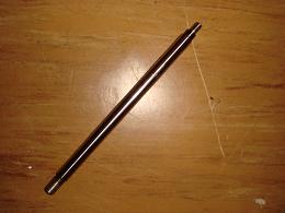
The system begins with the power of the motor. The motor works as all other motors whereas it converts electrical energy to mechanical energy. It fits snug under the base of the blender and is close to the blades of the blender. The idea of the motor relies on magnetism where one of the two main parts, the rotor, rotates due to a torque caused by the wires and magnetic field configuration. A voltage is applied to the lead battery wires originating from the AC plug that takes power from the wall socket. Along the shaft is the armature which is a set of electromagnets. This set up of magnets is constantly in rotation due to the opposite attraction of the magnetic field from the larger magnet and the wires around the armature. Electron flow changes constantly to allow for the constant rotation and magnetic flow. This axis is then attached through the motor box up until the opening of the blender. This rotation becomes transferred into the shaft of the blender axis. This same axis is connected to the two blades which are the tools necessary for the blending action.
http://electronics.howstuffworks.com/motor.htm
Product Dissasembly
Design for Manufacture and Assembly
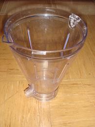
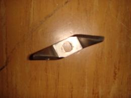
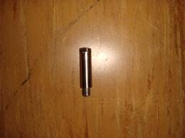
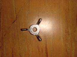
The current product is composed of 4 major components. The first being the pitcher, the next being the motor, the base and lastly the operator control. The pitcher is plastic and the mold is not a very difficult design to put through an assembly. It is this first piece of plastic that makes up the pitcher. There is then the additional blade assembly that is placed at the base of the plastic pitcher. This piece is also plastic and is a simple product to be modeled and made into plastic however the intricate part includes forming an area for an addition of a screw that fits the blade assembly. The production of the blades in the blade assembly is most likely taken from a slab of oddly shaped metal where slices of equivalent sizes can be taken in order to produce mass amounts of blades at one time. This is a helpful design decision that aides in the efficiency and productivity of the mechanical process. The blender blade setup uses two identical blades 90 degrees to each other that sit on top of one another. Simple washers and a long screw are straightforward pieces necessary for the overall assembly of the blade placed in the pitcher. There are small gradations on the side indicating liquid volume and these markings can also easily be etched into the plastic container. Taking into consideration the size of the machine used to etch these markings should be accounted for in the decided size of these markings as well as customer readability. The container handle size should be developed with the production process in mind making sure that the production of the handle design is within a reasonable capability of the productions team.
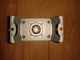
The second major component is the motor which is hidden inside the base and directly under the pitcher. This is usually an in stock purchase from another company that specializes in motors. However many more questions arise when adding an out of house product to an in house development. The problem of heat transfer must be thoroughly examined making sure that the heat produced from the motor and its components will not simply melt the parts nearby. This is not necessarily a design for manufacturing but rather an inquisition into the design specifications and capabilities. The placement of the motor is an important decision in the design because it is based upon its ability to be sufficiently mounted. The mounting clips must be under the blender base and they must be able to withstand the heat from the motor as well as slight movement associated with the vibrations from the motor. The mounting clips for the motor are an extension of the base and not an added addition which add to their stability but the manufacturer must make sure to place mounting clips at points that are available to be machined easily. Sometimes it is hard to extrude extra plastic pieces to form mounts in certain areas especially in a base similar to the design of this blender.
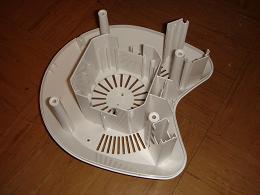
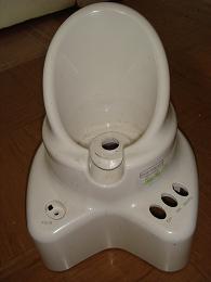
The third main component is the base itself. It is made of plastic and the decision on its form must be considered with the design aspect in mind as well. A plastic model is most likely mass produced but the thickness placement of its interior walls must be able to be made without construction errors or problems. Sometimes if the side walls or mounting walls of the base are too thin this could lead to ineffective design production. There is a limit to how thin a plastic piece can be made in the manufacturing process. These type of specifications must be readily available to the designers of the base in order to make sure to design around these manufacturing flaws. The best way to add to the ease of this manufacture is to create as little parts for the base as possible while maintaining a realistic manufacturing design. However the manufacturing aspect can be eased if numerous plastic base pieces that are easily manufactured can be arrested into the base rather than one intricate base piece. These pieces would most effectively allow for greater stability of the motor and overall blender than compared to a one piece base setup.
The last component is the operator control that allows the user to choose between two different blender speeds as well as an option to stop the blending. This set up is important because it harnesses the electrical wiring component of the blender. Wiring placement is important when dealing with such a product because the ability for wet liquids to dispel around or near the harness could lead to extreme danger or malfunction. The wiring must be designed far from any liquid aspect of the blender as well as far from the heat produced by the motor, however the wiring can be also sealed to maintain a cooler operating temperature as well as keeping the wires dry. Most importantly the wiring of the controller must circumvent the surrounding area of the base piece without getting in the way of the motor and must be able to be wrapped in a safe fashion. The wiring must have ample bend to be navigated inside the base but must also be thick enough to hold the power necessary from the motor.
Design for the Environment
With the research that we’ve done so far, we have found five strategies that if improved, could decrease the impact our product has on the environment. The major concerns include, but are not limited to, new concept development, low impact materials, manufacturing, maximizing first life, and end of life.
New Concept Development - By integrating several other functions in to the blender, it could reduce the need for other appliances within the kitchen. It’s current design featuring the nozzle at the base of the blender allows users to use the blender as both a blender and a pitcher.
Low Impact Materials – The majority of the parts of the blender are plastic which has an awful impact on the environment. It is difficult to recycle and even the process of recycling can emit harmful fumes. The packaging used, cardboard, could be changed to recycled cardboard.
Manufacturing – Further research should be done in to the manufacturing processes and perhaps there could be a reduction in the amount of waste materials.
Maximizing First Life – Clearer instructions on disassembly and cleaning could help decrease the possibility of breaking the blender while trying to do either. Breaking could lead the need to replace multiple parts and damaging the environment further.
End of Life – The motor of the blender could be recycled but the majority of the materials can not. The pressed plastic was made specifically for the blender thus it wouldn’t be reused for anything else, and is very difficult to recycle.
Failure Mode Effects and Analysis
The following chart represents the failure modes that have been agreed upon as the greatest possible failures of the blender. The purpose of a Failure Mode Effects and Analysis chart is to assess the risks involved in the process of using a product, and to determine the importance to deal with each mode of failure. This is done my estimating a value that will indicate the severity, occurance, and detection of each error, and multiplying the values together. In order to deal with these issues, the chart then offers a possible action to solve the error, and will again account for the severity, occurance, and detection. By this way, one can see how effective the improvement is.
| Item & Function | Failure Mode | Effects of Failure | S | Causes of Failure | O | Design Controls | D | RPN | Recommended Actions | Responsibility & Deadline | Actions Taken | S* | O* | D* | RPN* |
|---|---|---|---|---|---|---|---|---|---|---|---|---|---|---|---|
Motor
| Motor overheating | Motor will not be able to turn the blades and would make blender useless. | 8 | Motor could overheat if left on too long when trying to blend foods of a harder consistency | 6 | Testing fan output that assists in cooling motor, as well as testing motor at max speeds with a variety of loads. | 8 | 384 | Incorporate a switch in that would shut the blender off if the torque approached it failure point. | Manufacturer of Motor | N/A | 8 | 2 | 8 | 128 |
Blade
| Blade edge dulls | It will take longer to mix and smooth as well as making it more diffcult to break apart certain items. | 3 | Overuse and attempting to break apart dense, hard items. | 5 | Test blade with items of a variety of densities and composures. | 2 | 30 | Find an appropriate material, thickness, and angle that will be least likely to dull. | N/A | N/A | 3 | 2 | 3 | 18 |
Pitcher
| Plastic cracks | Items being blended will leak out side of blender. | 4 | Dropped from a high height. | 7 | Test stress on blender when dropped. | 3 | 84 | Test different shapes and wall thicknesses to find a contaner least likely to break. | N/A | N/A | 3 | 4 | 3 | 36 |
Handle
| Breaks off | No handle to carry blender. | 3 | Dropped from a high height. | 7 | Test snap together fits to identify breaking points. | 2 | 42 | Test other ways to fit parts together to find most cost effective solution | Assembler | N/A | 3 | 3 | 3 | 27 |
Motor Coupling
| Uncouples | Blade will not spin even while motor does. | 8 | Motor spins incorrect direction. | 2 | Test possible ways that would cause motor to spin in wrong direction. | 8 | 128 | Find a controller or switch that would deactivate motor if it were to start spinning in wrong direction. | Manufacturer | N/A | 8 | 1 | 7 | 56 |
Wiring
| Wire becomes disconnected | Current will be unable to power motor or similar function. | 8 | Wire tangled with moving parts. | 2 | Test different fastners to hold wire parts. | 3 | 48 | Test different positions for wire to be fastened to reduce tangling. | Assembler | N/A | 8 | 1 | 2 | 16 |
Upon examining the FMEA for the blender, it can be observed that the failures include issues that would make the product unable to be used entirely, and also ones in which it just becomes more of an inconvience to the consumer. Both issues are important to consider, and the difference in importance can be noted from the values in the chart. Malfunction of the motor, coupling, and wiring would disable use of the blender entirely, while cracks in components are not as significant. Examining the values in the chart for the motor overheating, it is obvious that it is a very severe issue, resulting in a 9, however it is not all that likely to occur explaining the 6 for occurance. A part suc as the motor that is not easily accesible to the user, makes it difficult to detect the failure. This is an example that justifies the method used to determine our values. These failure modes are often best dealt with by conducting tests to find the best way to create a product that is both cost effective and satisfies the user.
Mechanical Analysis
Calculating the change in temperature of the frozen additions into the blender: Assumptions:
1. Objects added to blender are at 0 degrees Celsius
2. Final temperature is unknown
3. Mass and specific heat of contents is equal to that of H20
4. Motor is not producing peak powers (80%)
5. Contents are 1000mL
Calculations:
Q – W = ΔE
mCpΔT – W = ΔE
ρH20 (ice) = .92g/mL
m = 1000mL *.92g/mL = 9200 g ice
Cp H20 = 2111.4J/(kg*K)
W = .8(500W) = 400J/sec
ω = 20000rpm *(min/60sec) *(2π rad/rot) = 2094.4rad/sec
r = .027m
m = .058kg
ΔE = 1/2mv^2/r = 1/2mrω^2 = ½*.058kg * .027m * (2094.4rad/sec)^2
ΔE = 1.63991J
Solving for Tfinal:
(Tf – Ti) = (ΔE + W)/mCp
Tf = Ti + (ΔE + W)/mCp
Tf = 0°C + (1.63991J + 400J)/(.058kg * 2111.4J/(kg*K))
Tf = 3.28°C
